YAMAHA YZ426F 2000 Betriebsanleitungen (in German)
Manufacturer: YAMAHA, Model Year: 2000, Model line: YZ426F, Model: YAMAHA YZ426F 2000Pages: 608, PDF-Größe: 45.52 MB
Page 181 of 608
INSP
ADJREGLAGE DU JEU DE SOUPAPES
VENTILSPIEL EINSTELLEN
6. Einstellen:
lVentilspiel
Arbeitsschritte:
lSteuerkettenspanner-Abdeckschraube
lockern.
lSteuerkettenspanner und Nockenwellen-
Lagerdeckel demontieren.
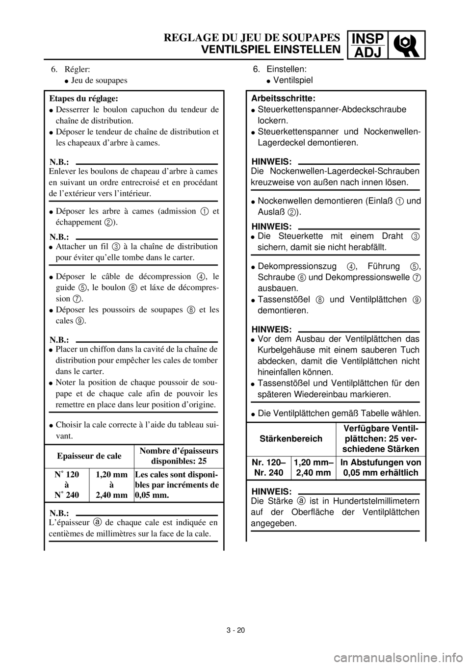
lNockenwellen demontieren (Einlaß 1 und
Auslaß 2).
lDekompressionszug 4, Führung 5,
Schraube 6 und Dekompressionswelle 7
ausbauen.
lTassenstößel 8 und Ventilplättchen 9
demontieren.
lDie Ventilplättchen gemäß Tabelle wählen.
StärkenbereichVerfügbare Ventil-
plättchen: 25 ver-
schiedene Stärken
Nr. 120–
Nr. 2401,20 mm–
2,40 mmIn Abstufungen von
0,05 mm erhältlich
HINWEIS:
Die Nockenwellen-Lagerdeckel-Schrauben
kreuzweise von außen nach innen lösen.
HINWEIS:
lDie Steuerkette mit einem Draht 3
sichern, damit sie nicht herabfällt.
HINWEIS:
lVor dem Ausbau der Ventilplättchen das
Kurbelgehäuse mit einem sauberen Tuch
abdecken, damit die Ventilplättchen nicht
hineinfallen können.
lTassenstößel und Ventilplättchen für den
späteren Wiedereinbau markieren.
HINWEIS:
Die Stärke a ist in Hundertstelmillimetern
auf der Oberfläche der Ventilplättchen
angegeben. 6. Régler:
lJeu de soupapes
Etapes du réglage:
lDesserrer le boulon capuchon du tendeur de
chaîne de distribution.
lDéposer le tendeur de chaîne de distribution et
les chapeaux d’arbre à cames.
lDéposer les arbre à cames (admission 1 et
échappement 2).
lDéposer le câble de décompression 4, le
guide 5, le boulon 6 et láxe de décompres-
sion 7.
lDéposer les poussoirs de soupapes 8 et les
cales 9.
lChoisir la cale correcte à l’aide du tableau sui-
vant.
Epaisseur de caleNombre d’épaisseurs
disponibles: 25
N˚ 120
à
N˚ 2401,20 mm
à
2,40 mm Les cales sont disponi-
bles par incréments de
0,05 mm.
N.B.:
Enlever les boulons de chapeau d’arbre à cames
en suivant un ordre entrecroisé et en procédant
de l’extérieur vers l’intérieur.
N.B.:
lAttacher un fil 3 à la chaîne de distribution
pour éviter qu’elle tombe dans le carter.
N.B.:
lPlacer un chiffon dans la cavité de la chaîne de
distribution pour empêcher les cales de tomber
dans le carter.
lNoter la position de chaque poussoir de sou-
pape et de chaque cale afin de pouvoir les
remettre en place dans leur position d’origine.
N.B.:
L’épaisseur a de chaque cale est indiquée en
centièmes de millimètres sur la face de la cale.
3 - 20
Page 182 of 608
3 - 21
INSP
ADJ
VALVE CLEARANCE ADJUSTMENT
lRound off the last digit of the installed pad
number to the nearest increment.
Last digit of pad
numberRounded value
0 or 2 0
5(NOT ROUNDED
OFF)
810
EXAMPLE:
Installed pad number = 148
Rounded off value = 150
lLocate the rounded-off value and the
measured valve clearance in the chart
“PAD SELECTION TABLE”. The field
where these two coordinates intersect
shows the new pad number to use.
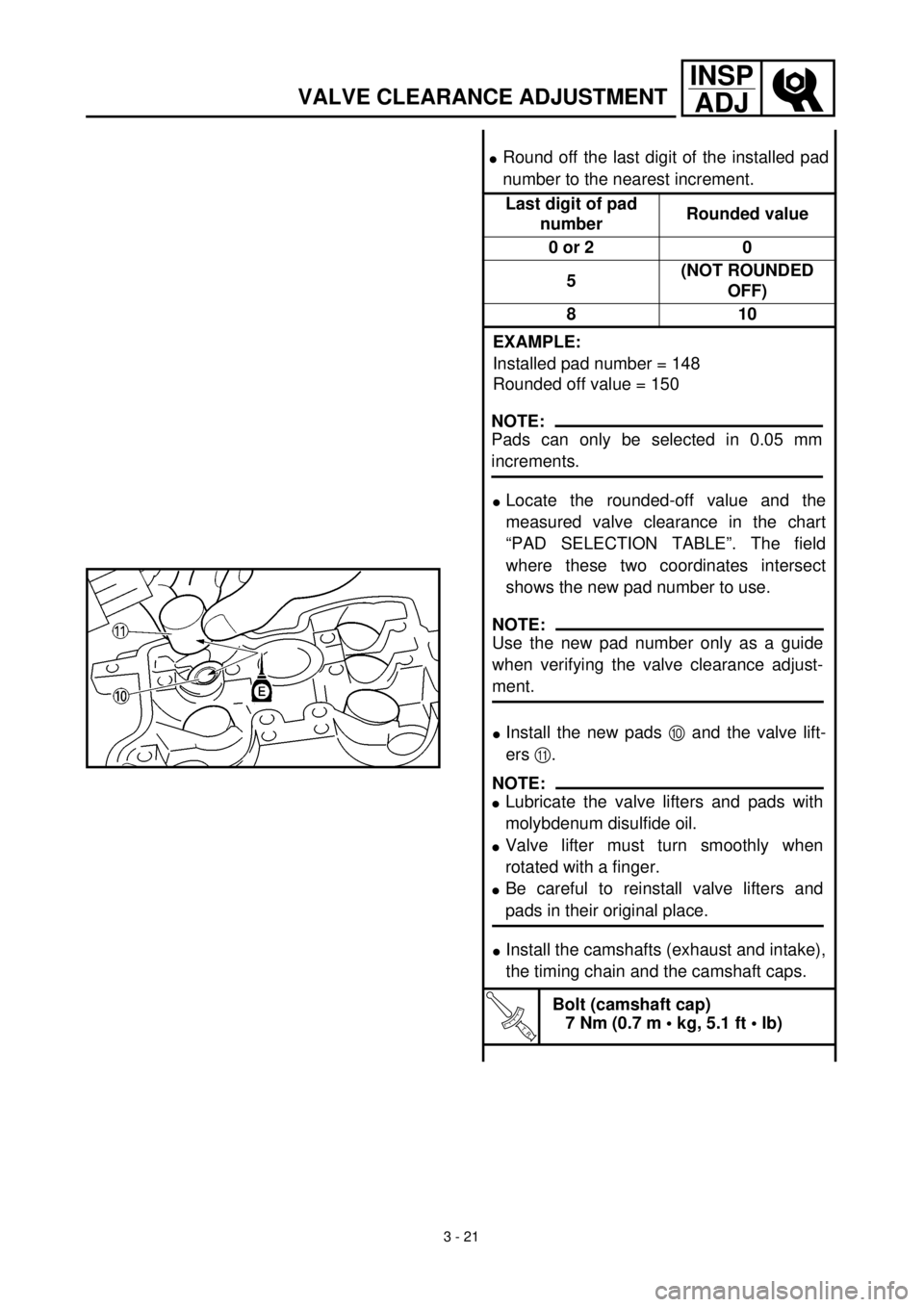
lInstall the new pads 0 and the valve lift-
ers A.
lInstall the camshafts (exhaust and intake),
the timing chain and the camshaft caps.
T R..
Bolt (camshaft cap)
7 Nm (0.7 m • kg, 5.1 ft • lb)
NOTE:
Pads can only be selected in 0.05 mm
increments.
NOTE:
Use the new pad number only as a guide
when verifying the valve clearance adjust-
ment.
NOTE:
lLubricate the valve lifters and pads with
molybdenum disulfide oil.
lValve lifter must turn smoothly when
rotated with a finger.
lBe careful to reinstall valve lifters and
pads in their original place.
Page 183 of 608
INSP
ADJ
3 - 21
REGLAGE DU JEU DE SOUPAPES
VENTILSPIEL EINSTELLEN
lHundertstel gemäß Tabelle runden.
Letzte Ziffer auf
dem PlättchenGerundeter Wert
0 oder 2 0
5 NICHT GERUNDET
810
BEISPIEL:
Nr. des ausgebauten Ventilplättchens = 148
Gerundeter Wert = 150
lGerundete Ventilplättchen-Nummer und
gemessenes Ventilspiel in der nachfolgen-
den Tabelle suchen. Aus dem Schnitt-
punkt der beiden Koordinaten ergibt sich
die neue Ventilplättchen-Stärke bzw.
-Nummer.
lNeue Ventilplättchen 0 und Tassenstößel
A einsetzen.
lNockenwellen (Einlaß und Auslaß), Steu-
erkette und die Nockenwellen-Lagerdec-
kel montieren.
T R..
Nockenwellen-Lagerdeckel-
Schraube
7 Nm (0,7 m • kg)
HINWEIS:
Ventilplättchen sind nur in Abstufungen von
0,05 mm erhältlich. Da werkseitig in der Ferti-
gung jedoch auch Ventilplättchen in 0,01-mm-
Stufen verwendet werden, ist das Auf- bzw.
Abrunden notwendig, um die nächstliegende
0,05-mm-Stufe zu bestimmen.
HINWEIS:
Bei einer Nachkontrolle dient die neue Ven-
tilplättchen-Stärke zunächst nur als
Bezugsgröße.
HINWEIS:
lDie Tassenstößel und Ventilplättchen mit
Molybdändisulfidöl schmieren.
lDie Tassenstößel müssen sich mühelos
mit einem Finger drehen lassen.
lDie Ventilplättchen und Tassenstößel müs-
sen an der ursprünglichen Stelle einge-
setzt werden.
lArrondir le dernier chiffre de la cale installée à
l’épaisseur de cale disponible la plus proche.
Dernier chiffre du
numéro de cale Chiffre arrondi
0 ou 2 0
5 (PAS ARRONDI)
810
EXEMPLE:
Numéro de cale installée = 148
Valeur arrondie = 150
lTrouver la valeur arrondie et la valeur mesurée
du jeu de soupapes sur la “TABLE DE
SELECTION DE CALES”. Le numéro de la
nouvelle cale se trouve à l’intersection de ces
deux coordonnées.
lInstaller les nouvelles cales 0 et les poussoirs
de soupapes A.
lInstaller les arbres à cames (admission et
échappement), la chaîne de distribution et les
chapeaux d’arbre à cames.
T R..
Boulon de chapeau d’arbre à cames
7 Nm (0,7 m • kg, 5,1 ft • lb)
N.B.:
Les cales ne peuvent être sélectionnées que par
incréments de 0,05 mm.
N.B.:
Ce nouveau numéro de cale est à utiliser comme
une première approximation de l’épaisseur de
cale nécessaire. Il faudra vérifier que le jeu
obtenu est correct.
N.B.:
lLubrifier les poussoirs de soupapes et les cales
avec de l’huile au bisulfure de molybdène.
lQuand on le fait tourner du doigt, un poussoir
de soupape doit tourner en douceur.
lPrendre soin de remettre les poussoirs de sou-
papes et les cales dans leur position d’origine.
Page 184 of 608
3 - 22
INSP
ADJ
VALVE CLEARANCE ADJUSTMENT
7. Install:
lAll removed parts
NOTE:
Install all removed parts in reversed order of
their removal. Note the following points.
lInstall the timing chain tensioner.
Refer to “CAMSHAFTS” section in the
CHAPTER 4.
NOTE:
lRefer to “CAMSHAFTS” section in the
CHAPTER 4.
lTurn the crankshaft counterclockwise sev-
eral turns so that the installed parts settle
into the right position.
lRecheck the valve clearance.
lIf the clearance is still incorrect, repeat all
the clearance adjustment steps until the
specified clearance is obtained.
Page 185 of 608
INSP
ADJREGLAGE DU JEU DE SOUPAPES
VENTILSPIEL EINSTELLEN
7. Montieren:
lAlle ausgebauten Teile
HINWEIS:
Alle ausgebauten Teile in umgekehrter Rei-
henfolge montieren. Dabei sind folgende
Punkte zu beachten.
lSteuerkettenspanner montieren.
Siehe unter “NOCKENWELLEN” im KAPI-
TEL 4.
HINWEIS:
lSiehe unter “VENTIL UND VENTIL-
FEDER” im KAPITEL 4.
lDie Nockenwelle mehrmals gegen den
Uhrzeigersinn drehen, damit sich die Bau-
teile richtig anpassen.
lVentilspiel nochmals kontrollieren.
lEntspricht die Messung nicht dem Soll-
wert, muß die Einstellung wiederholt wer-
den, bis das vorgeschriebene Ventilspiel
erreicht ist.
7. Monter:
lToutes les pièces enlevées
N.B.:
Remettre toutes les pièces enlevées en place dans
l’ordre inverse de leur dépose. Noter les points sui-
vants:
lMonter le tendeur de la chaîne de distribution.
Se reporter à la section “ARBRES A CAMES”
au CHAPITRE 4.
N.B.:
lSe reporter à la section “ARBRE A CAMES”
au CHAPITRE 4.
lFaire tourner plusieurs fois le vilebrequin dans
le sens inverse des aiguilles d’une montre afin
que les composants se mettent en place correc-
tement.
lVérifier une nouvelle fois le jeu de soupapes.
lSi le jeu reste incorrect, suivre à nouveau les
étapes du réglage du jeu de soupapes jusqu’à
obtention du jeu spécifié.
3 - 22
Page 186 of 608
3 - 23
INSP
ADJ
VALVE CLEARANCE ADJUSTMENT
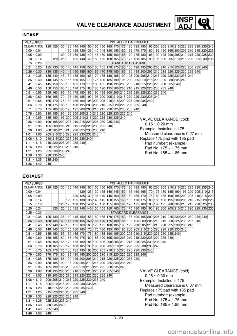
INTAKE
MEASURED
CLEARANCEINSTALLED PAD NUMBER
120 125 130 135 140 145 150 155 160 165 170
175 180 185 190 195 200 205 210 215 220 225 230 235 240
0.00 ~ 0.04 120 125 130 135 140 145 150
155160 165 170 175 180 185 190 195 200 205 210 215 220 225
0.05 ~ 0.09 120 125 130 135 140 145 150 155
160165 170 175 180 185 190 195 200 205 210 215 220 225 230
0.10 ~ 0.14
120 125 130 135 140 145 150 155 160 165170 175 180 185 190 195 200 205 210 215 220 225 230 235
0.15 ~ 0.20STANDARD CLEARANCE
0.21 ~ 0.25
125130135140145150155160165170175180 185 190 195 200 205 210 215 220 225 230 235240
0.26 ~ 0.30130135140145150155160165170175180185 190 195 200 205 210 215 220 225 230 235240
0.31 ~ 0.35 135 140 145 150 155 160 165 170 175 180 185 190 195 200 205 210 215 220 225 230 235240
0.36 ~ 0.40 140 145 150 155 160 165 170 175 180 185 190 195 200 205 210 215 220 225 230 235240
0.41 ~ 0.45 145 150 155 160 165 170 175 180 185 190 195 200 205 210 215 220 225 230 235240
0.46 ~ 0.50 150 155 160 165 170 175 180 185 190 195 200 205 210 215 220 225 230 235240
0.51 ~ 0.55 155 160 165 170 175 180 185 190 195 200 205 210 215 220 225 230 235240
0.56 ~ 0.60 160 165 170 175 180 185 190 195 200 205 210 215 220 225 230 235240
0.61 ~ 0.65 165 170 175 180 185 190 195 200 205 210 215 220 225 230 235240
0.66 ~ 0.70 170 175 180 185 190 195 200 205 210 215 220 225 230 235240
0.71 ~ 0.75 175 180 185 190 195 200 205 210 215 220 225 230 235240
0.76 ~ 0.80 180 185 190 195 200 205 210 215 220 225 230 235240
0.81 ~ 0.85 185 190 195 200 205 210 215 220 225 230 235240VALVE CLEARANCE (cold):
0.15 ~ 0.20 mm
Example: Installed is 175
Measured clearance is 0.27 mm
Replace 175 pad with 185 pad
Pad number: (example)
Pad No. 175 = 1.75 mm
Pad No. 185 = 1.85 mm0.86 ~ 0.90 190 195 200 205 210 215 220 225 230 235240
0.91 ~ 0.95 195 200 205 210 215 220 225 230 235240
0.96 ~ 1.00 200 205 210 215 220 225 230 235240
1.01 ~ 1.05 205 210 215 220 225 230 235240
1.06 ~ 1.10 210 215 220 225 230 235240
1.11 ~ 1.15 215 220 225 230 235240
1.16 ~ 1.20 220 225 230 235240
1.21 ~ 1.25 225 230 235240
1.26 ~ 1.30 230 235240
1.31 ~ 1.35 235240
1.36 ~ 1.40 240
EXHAUST
MEASURED
CLEARANCEINSTALLED PAD NUMBER
120 125 130 135 140 145 150 155 160 165 170
175 180 185 190 195 200 205 210 215 220 225 230 235 240
0.00 ~ 0.04 120 125 130 135 140
145150 155 160 165 170 175 180 185 190 195 200 205 210 215
0.05 ~ 0.09 120 125 130 135 140 145
150155 160 165 170 175 180 185 190 195 200 205 210 215 220
0.10 ~ 0.14
120 125 130 135 140 145 150 155160 165 170 175 180 185 190 195 200 205 210 215 220 225
0.15 ~ 0.19120 125 130 135 140 145 150 155 160165 170 175 180 185 190 195 200 205 210 215 220 225 230
0.20 ~ 0.24
120125130135140145150155160165170 175 180 185 190 195 200 205 210 215 220 225230235
0.25 ~ 0.30STANDARD CLEARANCE
0.31 ~ 0.35 125 130 135 140 145 150 155 160 165 170 175
180 185 190 195 200 205 210 215 220 225230235240
0.36 ~ 0.40130135140145150155160165170175180185 190 195 200 205 210 215 220 225230235240
0.41 ~ 0.45 135 140 145 150 155 160 165 170 175 180 185 190 195 200 205 210 215 220 225230235240
0.46 ~ 0.50 140 145 150 155 160 165 170 175 180 185 190 195 200 205 210 215 220 225230235240
0.51 ~ 0.55 145 150 155 160 165 170 175 180 185 190 195 200 205 210 215 220 225230235240
0.56 ~ 0.60 150 155 160 165 170 175 180 185 190 195 200 205 210 215 220 225230235240
0.61 ~ 0.65 155 160 165 170 175 180 185 190 195 200 205 210 215 220 225230235240
0.66 ~ 0.70 160 165 170 175 180 185 190 195 200 205 210 215 220 225230235240
0.71 ~ 0.75 165 170 175 180 185 190 195 200 205 210 215 220 225230235240
0.76 ~ 0.80 170 175 180 185 190 195 200 205 210 215 220 225230235240
0.81 ~ 0.85 175 180 185 190 195 200 205 210 215 220 225230235240
0.86 ~ 0.90 180 185 190 195 200 205 210 215 220 225230235240
0.91 ~ 0.95 185 190 195 200 205 210 215 220 225230235240
VALVE CLEARANCE (cold):
0.25 ~ 0.30 mm
Example: Installed is 175
Measured clearance is 0.37 mm
Replace 175 pad with 185 pad
Pad number: (example)
Pad No. 175 = 1.75 mm
Pad No. 185 = 1.85 mm0.96 ~ 1.00 190 195 200 205 210 215 220 225230235240
1.01 ~ 1.05 195 200 205 210 215 220 225230235240
1.06 ~ 1.10 200 205 210 215 220 225230235240
1.11 ~ 1.15 205 210 215 220 225230235240
1.16 ~ 1.20 210 215 220 225230235240
1.21 ~ 1.25 215 220 225230235240
1.26 ~ 1.30 220 225230235240
1.31 ~ 1.35 225230235240
1.36 ~ 1.40 230235240
1.41 ~ 1.45 235240
1.46 ~ 1.50 240
Page 187 of 608
INSP
ADJ
REGLAGE DU JEU DE SOUPAPES
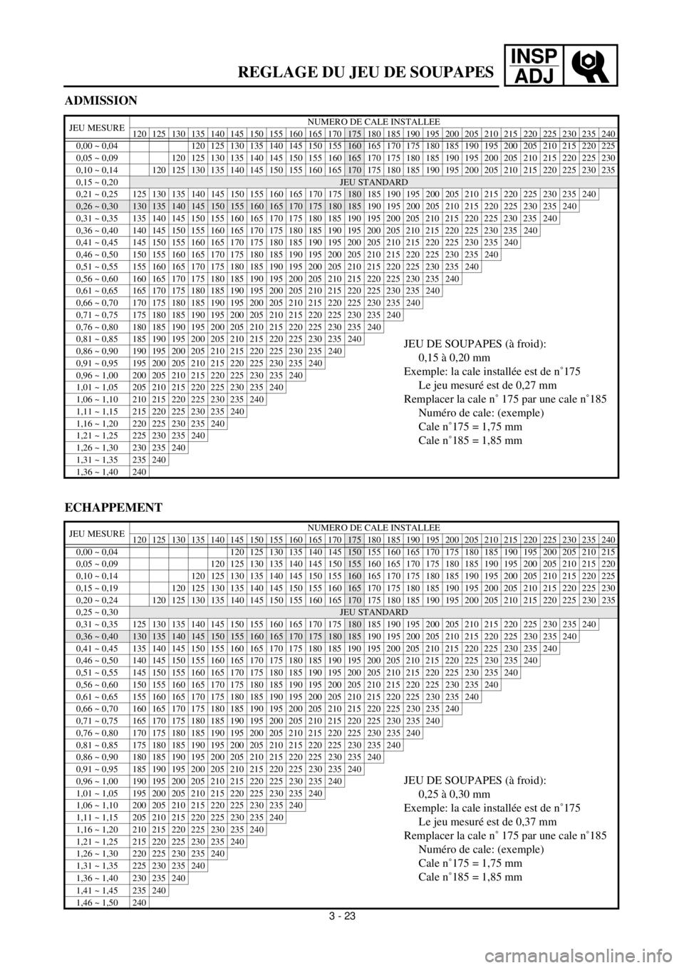
ADMISSION
JEU MESURENUMERO DE CALE INSTALLEE
120 125 130 135 140 145 150 155 160 165 170175 180 185 190 195 200 205 210 215 220 225 230 235 240
0,00 ~ 0,04 120 125 130 135 140 145 150
155160 165 170 175 180 185 190 195 200 205 210 215 220 225
0,05 ~ 0,09 120 125 130 135 140 145 150 155
160165 170 175 180 185 190 195 200 205 210 215 220 225 230
0,10 ~ 0,14
120 125 130 135 140 145 150 155 160 165170 175 180 185 190 195 200 205 210 215 220 225 230 235
0,15 ~ 0,20JEU STANDARD
0,21 ~ 0,25
125130135140145150155160165170175180 185 190 195 200 205 210 215 220 225 230 235240
0,26 ~ 0,30130135140145150155160165170175180185 190 195 200 205 210 215 220 225 230 235240
0,31 ~ 0,35 135 140 145 150 155 160 165 170 175 180 185 190 195 200 205 210 215 220 225 230 235240
0,36 ~ 0,40 140 145 150 155 160 165 170 175 180 185 190 195 200 205 210 215 220 225 230 235240
0,41 ~ 0,45 145 150 155 160 165 170 175 180 185 190 195 200 205 210 215 220 225 230 235240
0,46 ~ 0,50 150 155 160 165 170 175 180 185 190 195 200 205 210 215 220 225 230 235240
0,51 ~ 0,55 155 160 165 170 175 180 185 190 195 200 205 210 215 220 225 230 235240
0,56 ~ 0,60 160 165 170 175 180 185 190 195 200 205 210 215 220 225 230 235240
0,61 ~ 0,65 165 170 175 180 185 190 195 200 205 210 215 220 225 230 235240
0,66 ~ 0,70 170 175 180 185 190 195 200 205 210 215 220 225 230 235240
0,71 ~ 0,75 175 180 185 190 195 200 205 210 215 220 225 230 235240
0,76 ~ 0,80 180 185 190 195 200 205 210 215 220 225 230 235240
0,81 ~ 0,85 185 190 195 200 205 210 215 220 225 230 235240JEU DE SOUPAPES (à froid):
0,15 à 0,20 mm
Exemple: la cale installée est de n˚175
Le jeu mesuré est de 0,27 mm
Remplacer la cale n˚ 175 par une cale n˚185
Numéro de cale: (exemple)
Cale n˚175 = 1,75 mm
Cale n˚185 = 1,85 mm0,86 ~ 0,90 190 195 200 205 210 215 220 225 230 235240
0,91 ~ 0,95 195 200 205 210 215 220 225 230 235240
0,96 ~ 1,00 200 205 210 215 220 225 230 235240
1,01 ~ 1,05 205 210 215 220 225 230 235240
1,06 ~ 1,10 210 215 220 225 230 235240
1,11 ~ 1,15 215 220 225 230 235240
1,16 ~ 1,20 220 225 230 235240
1,21 ~ 1,25 225 230 235240
1,26 ~ 1,30 230 235240
1,31 ~ 1,35 235240
1,36 ~ 1,40 240
ECHAPPEMENT
JEU MESURENUMERO DE CALE INSTALLEE
120 125 130 135 140 145 150 155 160 165 170175 180 185 190 195 200 205 210 215 220 225 230 235 240
0,00 ~ 0,04 120 125 130 135 140
145150 155 160 165 170 175 180 185 190 195 200 205 210 215
0,05 ~ 0,09 120 125 130 135 140 145
150155 160 165 170 175 180 185 190 195 200 205 210 215 220
0,10 ~ 0,14
120 125 130 135 140 145 150 155160 165 170 175 180 185 190 195 200 205 210 215 220 225
0,15 ~ 0,19120 125 130 135 140 145 150 155 160165 170 175 180 185 190 195 200 205 210 215 220 225 230
0,20 ~ 0,24
120125130135140145150155160165170 175 180 185 190 195 200 205 210 215 220 225230235
0,25 ~ 0,30JEU STANDARD
0,31 ~ 0,35 125 130 135 140 145 150 155 160 165 170 175
180 185 190 195 200 205 210 215 220 225230235240
0,36 ~ 0,40130135140145150155160165170175180185 190 195 200 205 210 215 220 225230235240
0,41 ~ 0,45 135 140 145 150 155 160 165 170 175 180 185 190 195 200 205 210 215 220 225230235240
0,46 ~ 0,50 140 145 150 155 160 165 170 175 180 185 190 195 200 205 210 215 220 225230235240
0,51 ~ 0,55 145 150 155 160 165 170 175 180 185 190 195 200 205 210 215 220 225230235240
0,56 ~ 0,60 150 155 160 165 170 175 180 185 190 195 200 205 210 215 220 225230235240
0,61 ~ 0,65 155 160 165 170 175 180 185 190 195 200 205 210 215 220 225230235240
0,66 ~ 0,70 160 165 170 175 180 185 190 195 200 205 210 215 220 225230235240
0,71 ~ 0,75 165 170 175 180 185 190 195 200 205 210 215 220 225230235240
0,76 ~ 0,80 170 175 180 185 190 195 200 205 210 215 220 225230235240
0,81 ~ 0,85 175 180 185 190 195 200 205 210 215 220 225230235240
0,86 ~ 0,90 180 185 190 195 200 205 210 215 220 225230235240
0,91 ~ 0,95 185 190 195 200 205 210 215 220 225230235240
JEU DE SOUPAPES (à froid):
0,25 à 0,30 mm
Exemple: la cale installée est de n˚175
Le jeu mesuré est de 0,37 mm
Remplacer la cale n˚ 175 par une cale n˚185
Numéro de cale: (exemple)
Cale n˚175 = 1,75 mm
Cale n˚185 = 1,85 mm0,96 ~ 1,00 190 195 200 205 210 215 220 225230235240
1,01 ~ 1,05 195 200 205 210 215 220 225230235240
1,06 ~ 1,10 200 205 210 215 220 225230235240
1,11 ~ 1,15 205 210 215 220 225230235240
1,16 ~ 1,20 210 215 220 225230235240
1,21 ~ 1,25 215 220 225230235240
1,26 ~ 1,30 220 225230235240
1,31 ~ 1,35 225230235240
1,36 ~ 1,40 230235240
1,41 ~ 1,45 235240
1,46 ~ 1,50 240
3 - 23
Page 188 of 608
INSP
ADJ
VENTILSPIEL EINSTELLEN
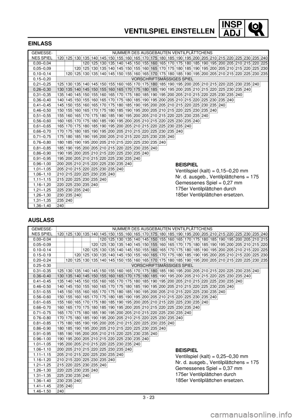
EINLASS
GEMESSE-
NES SPIELNUMMER DES AUSGEBAUTEN VENTILPLÄTTCHENS
120 125 130 135 140 145 150 155 160 165 170
175 180 185 190 195 200 205 210 215 220 225 230 235 240
0,00–0,04 120 125 130 135 140 145 150
155160 165 170 175 180 185 190 195 200 205 210 215 220 225
0,05–0,09 120 125 130 135 140 145 150 155
160165 170 175 180 185 190 195 200 205 210 215 220 225 230
0,10–0,14
120 125 130 135 140 145 150 155 160 165170 175 180 185 190 195 200 205 210 215 220 225 230 235
0,15–0,20VORSCHRIFTSMÄSSIGES SPIEL
0,21–0,25
125130135140145150155160165170175180 185 190 195 200 205 210 215 220 225 230 235240
0,26–0,30130135140145150155160165170175180185 190 195 200 205 210 215 220 225 230 235240
0,31–0,35 135 140 145 150 155 160 165 170 175 180 185 190 195 200 205 210 215 220 225 230 235240
0,36–0,40 140 145 150 155 160 165 170 175 180 185 190 195 200 205 210 215 220 225 230 235240
0,41–0,45 145 150 155 160 165 170 175 180 185 190 195 200 205 210 215 220 225 230 235240
0,46–0,50 150 155 160 165 170 175 180 185 190 195 200 205 210 215 220 225 230 235240
0,51–0,55 155 160 165 170 175 180 185 190 195 200 205 210 215 220 225 230 235240
0,56–0,60 160 165 170 175 180 185 190 195 200 205 210 215 220 225 230 235240
0,61–0,65 165 170 175 180 185 190 195 200 205 210 215 220 225 230 235240
0,66–0,70 170 175 180 185 190 195 200 205 210 215 220 225 230 235240
0,71–0,75 175 180 185 190 195 200 205 210 215 220 225 230 235240
0,76–0,80 180 185 190 195 200 205 210 215 220 225 230 235240
0,81–0,85 185 190 195 200 205 210 215 220 225 230 235240
BEISPIEL
Ventilspiel (kalt) = 0,15–0,20 mm
Nr. d. ausgeb., Ventilplättchens = 175
Gemessenes Spiel = 0,27 mm
175er Ventilplättchen durch
185er Ventilplättchen ersetzen.
0,86–0,90 190 195 200 205 210 215 220 225 230 235240
0,91–0,95 195 200 205 210 215 220 225 230 235240
0,96–1,00 200 205 210 215 220 225 230 235240
1,01–1,05 205 210 215 220 225 230 235240
1,06–1,10 210 215 220 225 230 235240
1,11–1,15 215 220 225 230 235240
1,16–1,20 220 225 230 235240
1,21–1,25 225 230 235240
1,26–1,30 230 235240
1,31–1,35 235240
1,36–1,40 240
AUSLASS
GEMESSE-
NES SPIELNUMMER DES AUSGEBAUTEN VENTILPLÄTTCHENS
120 125 130 135 140 145 150 155 160 165 170
175 180 185 190 195 200 205 210 215 220 225 230 235 240
0.00–0.04 120 125 130 135 140
145150 155 160 165 170 175 180 185 190 195 200 205 210 215
0.05–0.09 120 125 130 135 140 145
150155 160 165 170 175 180 185 190 195 200 205 210 215 220
0.10–0.14
120 125 130 135 140 145 150 155160 165 170 175 180 185 190 195 200 205 210 215 220 225
0.15–0.19120 125 130 135 140 145 150 155 160165 170 175 180 185 190 195 200 205 210 215 220 225 230
0.20–0.24
120125130135140145150155160165170 175 180 185 190 195 200 205 210 215 220 225230235
0.25–0.30VORSCHRIFTSMÄSSIGES SPIEL
0.31–0.35 125 130 135 140 145 150 155 160 165 170 175
180 185 190 195 200 205 210 215 220 225230235240
0.36–0.40130135140145150155160165170175180185 190 195 200 205 210 215 220 225230235240
0.41–0.45 135 140 145 150 155 160 165 170 175 180 185 190 195 200 205 210 215 220 225230235240
0.46–0.50 140 145 150 155 160 165 170 175 180 185 190 195 200 205 210 215 220 225230235240
0.51–0.55 145 150 155 160 165 170 175 180 185 190 195 200 205 210 215 220 225230235240
0.56–0.60 150 155 160 165 170 175 180 185 190 195 200 205 210 215 220 225230235240
0.61–0.65 155 160 165 170 175 180 185 190 195 200 205 210 215 220 225230235240
0.66–0.70 160 165 170 175 180 185 190 195 200 205 210 215 220 225230235240
0.71–0.75 165 170 175 180 185 190 195 200 205 210 215 220 225230235240
0.76–0.80 170 175 180 185 190 195 200 205 210 215 220 225230235240
0.81–0.85 175 180 185 190 195 200 205 210 215 220 225230235240
0.86–0.90 180 185 190 195 200 205 210 215 220 225230235240
0.91–0.95 185 190 195 200 205 210 215 220 225230235240
BEISPIEL
Ventilspiel (kalt) = 0,25–0,30 mm
Nr. d. ausgeb., Ventilplättchens = 175
Gemessenes Spiel = 0,37 mm
175er Ventilplättchen durch
185er Ventilplättchen ersetzen.
0.96–1.00 190 195 200 205 210 215 220 225230235240
1.01–1.05 195 200 205 210 215 220 225230235240
1.06–1.10 200 205 210 215 220 225230235240
1.11–1.15 205 210 215 220 225230235240
1.16–1.20 210 215 220 225230235240
1.21–1.25 215 220 225230235240
1.26–1.30 220 225230235240
1.31–1.35 225230235240
1.36–1.40 230235240
1.41–1.45 235240
1.46–1.50 240
3 - 23
Page 189 of 608

INSP
ADJ
MEMO
Page 190 of 608
3 - 24
INSP
ADJ
CHASSIS/BRAKE SYSTEM AIR BLEEDING
EC360000
CHASSIS
EC361012
BRAKE SYSTEM AIR BLEEDING
WARNING
Bleed the brake system if:
lThe system has been disassembled.
lA brake hose has been loosened or
removed.
lThe brake fluid is very low.
lThe brake operation is faulty.
A dangerous loss of braking performance
may occur if the brake system is not prop-
erly bleed.
1. Remove:
lMaster cylinder cap
lDiaphragm
lProtector (rear brake)
2. Bleed:
lBrake fluid
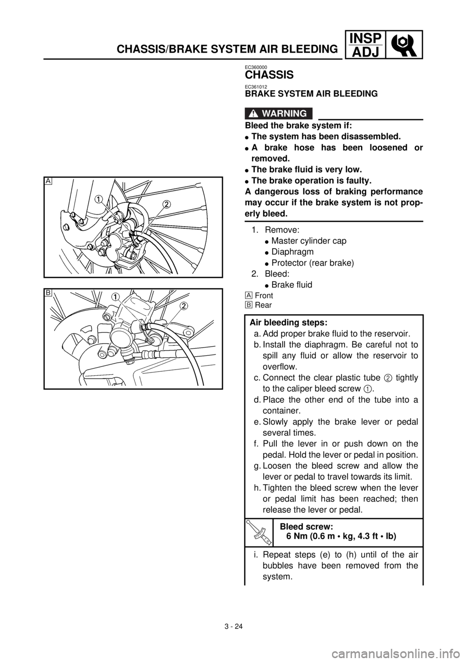
Front
õRear
Air bleeding steps:
a. Add proper brake fluid to the reservoir.
b. Install the diaphragm. Be careful not to
spill any fluid or allow the reservoir to
overflow.
c. Connect the clear plastic tube 2 tightly
to the caliper bleed screw 1.
d. Place the other end of the tube into a
container.
e. Slowly apply the brake lever or pedal
several times.
f. Pull the lever in or push down on the
pedal. Hold the lever or pedal in position.
g. Loosen the bleed screw and allow the
lever or pedal to travel towards its limit.
h. Tighten the bleed screw when the lever
or pedal limit has been reached; then
release the lever or pedal.
T R..
Bleed screw:
6 Nm (0.6 m • kg, 4.3 ft • lb)
i. Repeat steps (e) to (h) until of the air
bubbles have been removed from the
system.
õ