engine YAMAHA YZ450F 2005 Owner's Guide
[x] Cancel search | Manufacturer: YAMAHA, Model Year: 2005, Model line: YZ450F, Model: YAMAHA YZ450F 2005Pages: 646, PDF Size: 16.06 MB
Page 89 of 646
SPEC
2 - 18
EC220001
GENERAL TORQUE SPECIFICATIONS
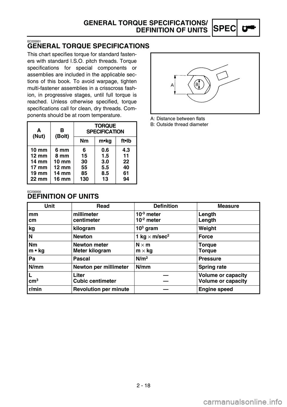
This chart specifies torque for standard fasten-
ers with standard I.S.O. pitch threads. Torque
specifications for special components or
assemblies are included in the applicable sec-
tions of this book. To avoid warpage, tighten
multi-fastener assemblies in a crisscross fash-
ion, in progressive stages, until full torque is
reached. Unless otherwise specified, torque
specifications call for clean, dry threads. Com-
ponents should be at room temperature.
A: Distance between flats
B: Outside thread diameter
EC230000
DEFINITION OF UNITS
A
(Nut)B
(Bolt)TORQUE
SPECIFICATION
Nm mkg ftlb
10 mm
12 mm
14 mm
17 mm
19 mm
22 mm6 mm
8 mm
10 mm
12 mm
14 mm
16 mm6
15
30
55
85
1300.6
1.5
3.0
5.5
8.5
134.3
11
22
40
61
94
Unit Read Definition Measure
mm
cmmillimeter
centimeter10
-3 meter
10-2 meterLength
Length
kg kilogram 10
3 gram Weight
N Newton 1 kg
× m/sec
2 Force
Nm
m kgNewton meter
Meter kilogramN
× m
m
× kgTorque
Torque
Pa Pascal N/m
2Pressure
N/mm Newton per millimeter N/mm Spring rate
L
cm
3 Liter
Cubic centimeter—
—Volume or capacity
Volume or capacity
r/min Revolution per minute—Engine speed
GENERAL TORQUE SPECIFICATIONS/
DEFINITION OF UNITS
Page 130 of 646
2 - 21
SPECCABLE ROUTING DIAGRAM
EC240000
CABLE ROUTING DIAGRAM
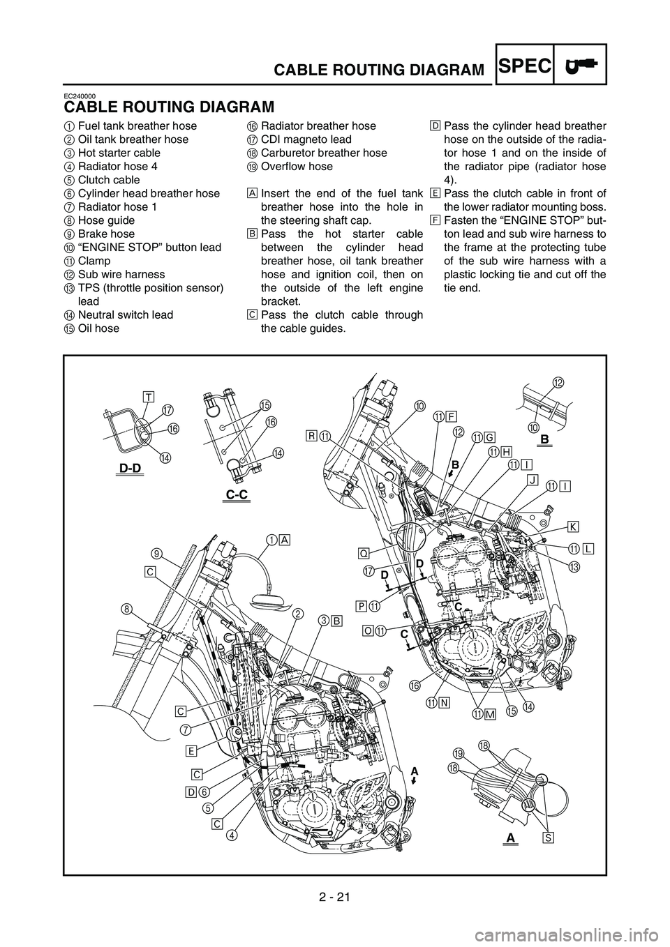
1Fuel tank breather hose
2Oil tank breather hose
3Hot starter cable
4Radiator hose 4
5Clutch cable
6Cylinder head breather hose
7Radiator hose 1
8Hose guide
9Brake hose
0“ENGINE STOP” button lead
AClamp
BSub wire harness
CTPS (throttle position sensor)
lead
DNeutral switch lead
EOil hoseFRadiator breather hose
GCDI magneto lead
HCarburetor breather hose
IOverflow hose
ÈInsert the end of the fuel tank
breather hose into the hole in
the steering shaft cap.
ÉPass the hot starter cable
between the cylinder head
breather hose, oil tank breather
hose and ignition coil, then on
the outside of the left engine
bracket.
ÊPass the clutch cable through
the cable guides.ËPass the cylinder head breather
hose on the outside of the radia-
tor hose 1 and on the inside of
the radiator pipe (radiator hose
4).
ÌPass the clutch cable in front of
the lower radiator mounting boss.
ÍFasten the “ENGINE STOP” but-
ton lead and sub wire harness to
the frame at the protecting tube
of the sub wire harness with a
plastic locking tie and cut off the
tie end.
B
0
C-C
D-D
B
A
AB
DD
CC
F
D G
F
D
A
G
A
A
F
AE
A
DC A A A A B A 0
1
2
3
4 5 6 7 89
Ì
Ë
ÊÉ ÈÙÍ
Î
Ï
Ð
Ð Ñ
A
Ô Õ Ø
Ú HIH
E Û
Ò
Ö ×
Ê Ê Ê
Ó
Page 131 of 646

2 - 21
SPEC
KABELFÜHRUNGSDIAGRAMME
1Kraftstofftank-Belüftungsschlauch
2Öltank-Belüftungsschlauch
3Warmstartzug
4Kühler-Schlauch 4
5Kupplungszug
6Zylinderkopf-Entlüftungsschlauch
7Kühler-Schlauch 1
8Schlauchführung
9Bremsschlauch
0Kabel des Motorstoppschalters “ENGINE STOP”
AKlemme
BNebenkabelbaum
CDrosselklappensensor-Kabel
DLeerlaufschalter-Kabel
EÖlschlauch
FKühler-Entlüftungsschlauch
GLichtmaschinen-Kabel
HVergaser-Entlüftungsschlauch
IÜberlaufschlauch
ÈDes Ende des Kraftstofftank-Belüftungs-
schlauchs durch die Bohrung in der Lenkkopf-
Abdeckung stecken.
ÉDen Warmstartzug zwischen dem Zylinderkopf-
Entlüftungsschlauch, dem Öltank-Belüftungs-
schlauch und der Zündspule führen und dann an
der Außenseite der linken Motorhalterung ent-
langführen.
ÊDen Kupplungszug durch die Kabelführungen
leiten.
ËDen Zylinderkopf-Entlüftungsschlauch über den
Kühlerschlauch 1 und das Kühlerrohr (Kühler-
schlauch 4) führen.
ÌDen Kupplungszug vor der unteren Kühlerbefe-
stigung führen.
ÍDas Kabel des Motorstoppschalters “ENGINE
STOP” und den Nebenkabelbaum im Bereich
der Nebenkabelbaum-Schutzhülle mit einem
Kabelbinder am Rahmen befestigen und das
Ende abschneiden.
DIAGRAMME D’ACHEMINEMENT DES CABLES
KABELFÜHRUNGSDIAGRAMME
DIAGRAMME
D’ACHEMINEMENT DES CABLES
1Durit de mise à l’air du réservoir de carburant
2Durit de mise à l’air du réservoir d’huile
3Câble de démarrage à chaud
4Durit de radiateur 4
5Câble d’embrayage
6Durit de mise à l’air de la culasse
7Durit de radiateur 1
8Guide de durit
9Durit de frein
0Fil du bouton “ENGINE STOP”
ACollier à pince
BFaisceau de fils secondaire
CFil du capteur de position de papillon des gaz
DFil du contacteur de point mort
EDurit d’huile
FDurit de mise à l’air du radiateur
GFil du volant magnétique CDI
HDurit de mise à l’air du carburateur
IDurit de trop-plein
ÈInsérer l’extrémité de la durit de mise à l’air du réser-
voir de carburant dans le trou du capuchon de l’arbre
de direction.
ÉAcheminer le câble de démarrage à chaud entre la
durit de mise à l’air de la culasse, la durit de mise à
l’air du réservoir d’huile et la bobine d’allumage,
puis à l’extérieur du support de moteur gauche.
ÊAcheminer le câble d’embrayage dans les guide-
câbles.
ËAcheminer la durit de mise à l’air de la culasse à
l’extérieur de la durit de radiateur 1 et à l’intérieur du
tuyau de radiateur (durit de radiateur 4).
ÌAcheminer le câble d’embrayage devant la noix de
montage inférieure du radiateur.
ÍFixer le fil du bouton “ENGINE STOP” et le faisceau
de fils secondaire au cadre au niveau du tube de pro-
tection du faisceau de fils secondaire, à l’aide d’un
collier en plastique. Couper ensuite l’extrémité du
collier.
Page 132 of 646

2 - 22
SPECCABLE ROUTING DIAGRAM
ÎFasten the “ENGINE STOP” but-
ton lead and sub wire harness to
the frame at the protecting tube
for the “ENGINE STOP” button
lead with a plastic locking tie and
cut off the tie end.
ÏFasten the sub wire harness and
hot starter cable to the frame at
the white tape for the sub wire
harness with a plastic locking tie
and cut off the tie end.
ÐFasten the sub wire harness to
the frame with a plastic locking
tie and cut off the tie end.
ÑPass the sub wire harness
between the engine brackets.ÒMake sure that the TPS coupler
does not go outside the chassis.
ÓFasten the TPS lead to the
frame with a plastic band.
ÔFasten the neutral switch lead
and oil hose together with a
plastic locking tie and cut off the
tie end.
ÕFasten the neutral switch lead to
the frame with a plastic band.
ÖFasten the neutral switch lead,
CDI magneto lead and radiator
breather hose to the frame with
a plastic band.×Fasten the neutral switch lead,
CDI magneto lead and radiator
breather hose to the frame with
a plastic locking tie and cut off
the tie end.
ØPass the neutral switch lead,
CDI magneto lead and radiator
breather hose between the radi-
ator and frame.
ÙFasten the neutral switch lead
and CDI magneto lead to the
cable guide at their protecting
tubes with a plastic locking tie
and cut off the tie end.
ÚPass the carburetor breather
hoses and overflow hose so that
all there hoses do not contact
the rear shock absorber.
B
0
C-C
D-D
B
A
AB
DD
CC
F
D G
F
D
A
G
A
A
F
AE
A
DC A A A A B A 0
1
2
3
4 5 6 7 89
Ì
Ë
ÊÉ ÈÙÍ
Î
Ï
Ð
Ð Ñ
A
Ô Õ Ø
Ú HIH
E Û
Ò
Ö ×
Ê Ê Ê
Ó
Page 133 of 646

2 - 22
SPEC
ÎDas Kabel des Motorstoppschalters “ENGINE
STOP” und den Nebenkabelbaum im Bereich
der Schutzhülle vom Kabel des Motorstopp-
schalters “ENGINE STOP” mit einem Kabelbin-
der am Rahmen befestigen und das Ende
abschneiden.
ÏDen Nebenkabelbaum und den Warmstartzug
an der mit weißem Band am Nebenkabelbaum
markierten Stelle mit einem Kabelbinder am
Rahmen befestigen und das Ende abschneiden.
ÐDen Nebenkabelbaum mit einem Kabelbinder
am Rahmen befestigen und das Ende abschnei-
den.
ÑDen Nebenkabelbaum zwischen die Motorhalte-
rungen führen.
ÒSicherstellen, daß der Drosselklappensensor-
Steckverbinder nicht am Fahrgestell herausragt.
ÓDas Drosselklappensensor-Kabel mit einem
Kunststoffbinder am Rahmen befestigen.
ÔDas Leerlaufschalter-Kabel und den Ölschlauch
mit einem Kabelbinder zusammenbinden und
das Ende abschneiden.
ÕDas Leerlaufschalter-Kabel mit einem Kunst-
stoffbinder am Rahmen befestigen.
ÖDas Leerlaufschalter-Kabel, das Lichtmaschi-
nen-Kabel und den Kühler-Entlüftungsschlauch
mit einem Kunststoffbinder am Rahmen befesti-
gen.
×Das Leerlaufschalter-Kabel, das Lichtmaschi-
nen-Kabel und den Kühler-Entlüftungsschlauch
mit einem Kabelbinder am Rahmen befestigen
und das Ende abschneiden.
ØDas Leerlaufschalter-Kabel, das Lichtmaschi-
nen-Kabel und den Kühler-Entlüftungsschlauch
zwischen Kühler und Rahmen führen.
ÙDas Leerlaufschalter-Kabel und das Lichtma-
schinen-Kabel an deren Schutzhüllen mit einem
Kunststoffbinder im Bereich deren Schutzhüllen
an der Kabelführung befestigen und das Ende
abschneiden.
ÚDie Vergaser-Entlüftungs- und Überlaufschläu-
che so führen, daß sie das Federbein nicht
berühren.
DIAGRAMME D’ACHEMINEMENT DES CABLES
KABELFÜHRUNGSDIAGRAMME
ÎFixer le fil du bouton “ENGINE STOP” et le faisceau
de fils secondaire au cadre au niveau du tube de pro-
tection du fil du bouton “ENGINE STOP”, à l’aide
d’un collier en plastique. Couper ensuite l’extrémité
du collier.
ÏFixer le faisceau de fils secondaire et le câble de
démarrage à chaud au cadre au niveau de bande blan-
che du faisceau de fils secondaire, à l’aide d’un col-
lier en plastique. Couper ensuite l’extrémité du
collier.
ÐFixer le faisceau de fils secondaire au cadre à l’aide
d’un collier en plastique et couper l’extrémité du col-
lier.
ÑAcheminer le faisceau de fils secondaire entre les
supports de moteur.
ÒVeiller à ce que la fiche rapide du capteur de position
de papillon des gaz ne sorte pas du châssis.
ÓFixer le fil du capteur de position de papillon des gaz
au cadre à l’aide d’un collier réutilisable.
ÔAttacher ensemble le fil du contacteur de point mort
et la durit d’huile à l’aide d’un collier en plastique et
couper l’extrémité du collier.
ÕFixer le fil du contacteur de point mort au cadre à
l’aide d’un collier réutilisable.
ÖFixer le fil du contacteur de point mort, le fil du
volant magnétique CDI et la durit de mise à l’air du
radiateur au cadre à l’aide d’un collier réutilisable.
×Fixer le fil du contacteur de point mort, le fil du
volant magnétique CDI et la durit de mise à l’air du
radiateur au cadre à l’aide d’un collier en plastique et
couper l’extrémité du collier.
ØAcheminer le fil du contacteur de point mort, le fil du
volant magnétique CDI et la durit de mise à l’air du
radiateur entre le radiateur et le cadre.
ÙFixer le fil du contacteur de point mort et le fil du
volant magnétique CDI au guide-câbles au niveau de
leurs tubes de protection, à l’aide d’un collier en plas-
tique. Couper ensuite l’extrémité du collier.
ÚAcheminer les durits de mise à l’air du carburateur et
la durit de trop-plein de manière à ce qu’aucune
d’elles n’entre en contact avec l’amortisseur arrière.
Page 140 of 646

2 - 26
SPECCABLE ROUTING DIAGRAM
1Throttle cable
2Fuel tank breather hose
3Clamp
4Clutch cable
5Hot starter cable
6“ENGINE STOP” button lead
7Brake hose
8Hose guideÈFasten the “ENGINE STOP” but-
ton lead to the handlebar with
the plastic band.
ÉPass the brake hose in front of
the number plate.
3
6
40˚±10˚
A
12
3
4
5
6
7
8 È
É
A
Page 141 of 646

2 - 26
SPEC
1Gaszug
2Kraftstofftank-Belüftungsschlauch
3Klemme
4Kupplungszug
5Warmstartzug
6Kabel des Motorstoppschalters “ENGINE STOP”
7Bremsschlauch
8Schlauchführung
ÈDas Kabel des Motorstoppschalters “ENGINE
STOP” mit einem Kunststoffbinder am Lenker
befestigen.
ÉDen Bremsschlauch an der Vorderseite des
Nummernschildes entlangführen.
DIAGRAMME D’ACHEMINEMENT DES CABLES
KABELFÜHRUNGSDIAGRAMME
1Câble des gaz
2Durit de mise à l’air du réservoir de carburant
3Collier à pince
4Câble d’embrayage
5Câble de démarrage à chaud
6Fil du bouton “ENGINE STOP”
7Durit de frein
8Guide de durit
ÈFixer le fil du bouton “ENGINE STOP” au guidon à
l’aide du collier réutilisable.
ÉAcheminer la durit de frein devant la plaque d’identi-
fication.
Page 142 of 646
3 - 1
INSP
ADJ
MAINTENANCE INTERVALS
EC300000
REGULAR INSPECTION AND ADJUSTMENTS
MAINTENANCE INTERVALS
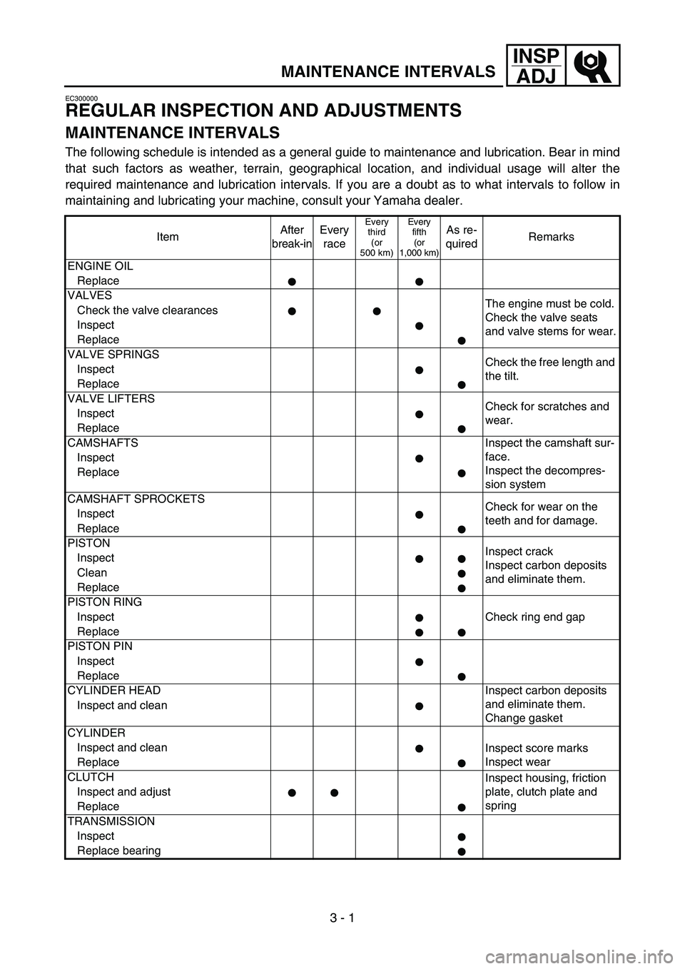
The following schedule is intended as a general guide to maintenance and lubrication. Bear in mind
that such factors as weather, terrain, geographical location, and individual usage will alter the
required maintenance and lubrication intervals. If you are a doubt as to what intervals to follow in
maintaining and lubricating your machine, consult your Yamaha dealer.
ItemAfter
break-inEvery
race
Every
third
(or
500 km)Every
fifth
(or
1,000 km)As re-
quiredRemarks
ENGINE OIL
Replace
VALVES
The engine must be cold.
Check the valve seats
and valve stems for wear. Check the valve clearances
Inspect
Replace
VALVE SPRINGS
Check the free length and
the tilt. Inspect
Replace
VALVE LIFTERS
Check for scratches and
wear. Inspect
Replace
CAMSHAFTS Inspect the camshaft sur-
face.
Inspect the decompres-
sion system Inspect
Replace
CAMSHAFT SPROCKETS
Check for wear on the
teeth and for damage. Inspect
Replace
PISTON
Inspect crack
Inspect carbon deposits
and eliminate them. Inspect
Clean
Replace
PISTON RING
Check ring end gap Inspect
Replace
PISTON PIN
Inspect
Replace
CYLINDER HEAD Inspect carbon deposits
and eliminate them.
Change gasket Inspect and clean
CYLINDER
Inspect and clean
Inspect score marks
Inspect wear
Replace
CLUTCH
Inspect housing, friction
plate, clutch plate and
spring Inspect and adjust
Replace
TRANSMISSION
Inspect
Replace bearing
Page 151 of 646
3 - 4
INSP
ADJ
PRE-OPERATION INSPECTION AND MAINTENANCE
EC320000
PRE-OPERATION INSPECTION AND MAINTENANCE
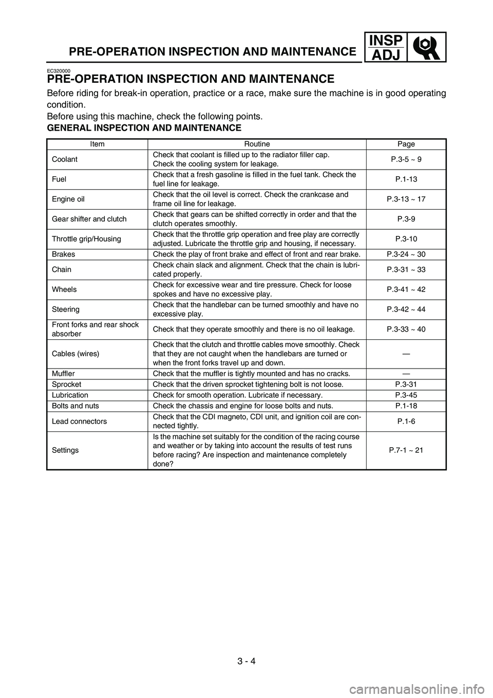
Before riding for break-in operation, practice or a race, make sure the machine is in good operating
condition.
Before using this machine, check the following points.
GENERAL INSPECTION AND MAINTENANCE
Item Routine Page
CoolantCheck that coolant is filled up to the radiator filler cap.
Check the cooling system for leakage.P.3-5 ~ 9
FuelCheck that a fresh gasoline is filled in the fuel tank. Check the
fuel line for leakage.P.1-13
Engine oilCheck that the oil level is correct. Check the crankcase and
frame oil line for leakage.P.3-13 ~ 17
Gear shifter and clutchCheck that gears can be shifted correctly in order and that the
clutch operates smoothly.P.3-9
Throttle grip/HousingCheck that the throttle grip operation and free play are correctly
adjusted. Lubricate the throttle grip and housing, if necessary.P.3-10
Brakes Check the play of front brake and effect of front and rear brake. P.3-24 ~ 30
ChainCheck chain slack and alignment. Check that the chain is lubri-
cated properly.P.3-31 ~ 33
WheelsCheck for excessive wear and tire pressure. Check for loose
spokes and have no excessive play.P.3-41 ~ 42
SteeringCheck that the handlebar can be turned smoothly and have no
excessive play.P.3-42 ~ 44
Front forks and rear shock
absorberCheck that they operate smoothly and there is no oil leakage. P.3-33 ~ 40
Cables (wires)Check that the clutch and throttle cables move smoothly. Check
that they are not caught when the handlebars are turned or
when the front forks travel up and down.—
Muffler Check that the muffler is tightly mounted and has no cracks.—
Sprocket Check that the driven sprocket tightening bolt is not loose. P.3-31
Lubrication Check for smooth operation. Lubricate if necessary. P.3-45
Bolts and nuts Check the chassis and engine for loose bolts and nuts. P.1-18
Lead connectorsCheck that the CDI magneto, CDI unit, and ignition coil are con-
nected tightly.P.1-6
SettingsIs the machine set suitably for the condition of the racing course
and weather or by taking into account the results of test runs
before racing? Are inspection and maintenance completely
done?P.7-1 ~ 21
Page 154 of 646
3 - 5
INSP
ADJ
EC350000
ENGINE
EC351011
COOLANT LEVEL INSPECTION
WARNING
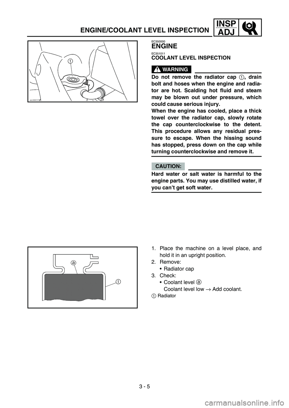
Do not remove the radiator cap
1, drain
bolt and hoses when the engine and radia-
tor are hot. Scalding hot fluid and steam
may be blown out under pressure, which
could cause serious injury.
When the engine has cooled, place a thick
towel over the radiator cap, slowly rotate
the cap counterclockwise to the detent.
This procedure allows any residual pres-
sure to escape. When the hissing sound
has stopped, press down on the cap while
turning counterclockwise and remove it.
CAUTION:
Hard water or salt water is harmful to the
engine parts. You may use distilled water, if
you can’t get soft water.
1. Place the machine on a level place, and
hold it in an upright position.
2. Remove:
Radiator cap
3. Check:
Coolant level a
Coolant level low → Add coolant.
1Radiator
ENGINE/COOLANT LEVEL INSPECTION