YAMAHA YZ450F 2010 Owners Manual
Manufacturer: YAMAHA, Model Year: 2010, Model line: YZ450F, Model: YAMAHA YZ450F 2010Pages: 230, PDF Size: 14.09 MB
Page 91 of 230
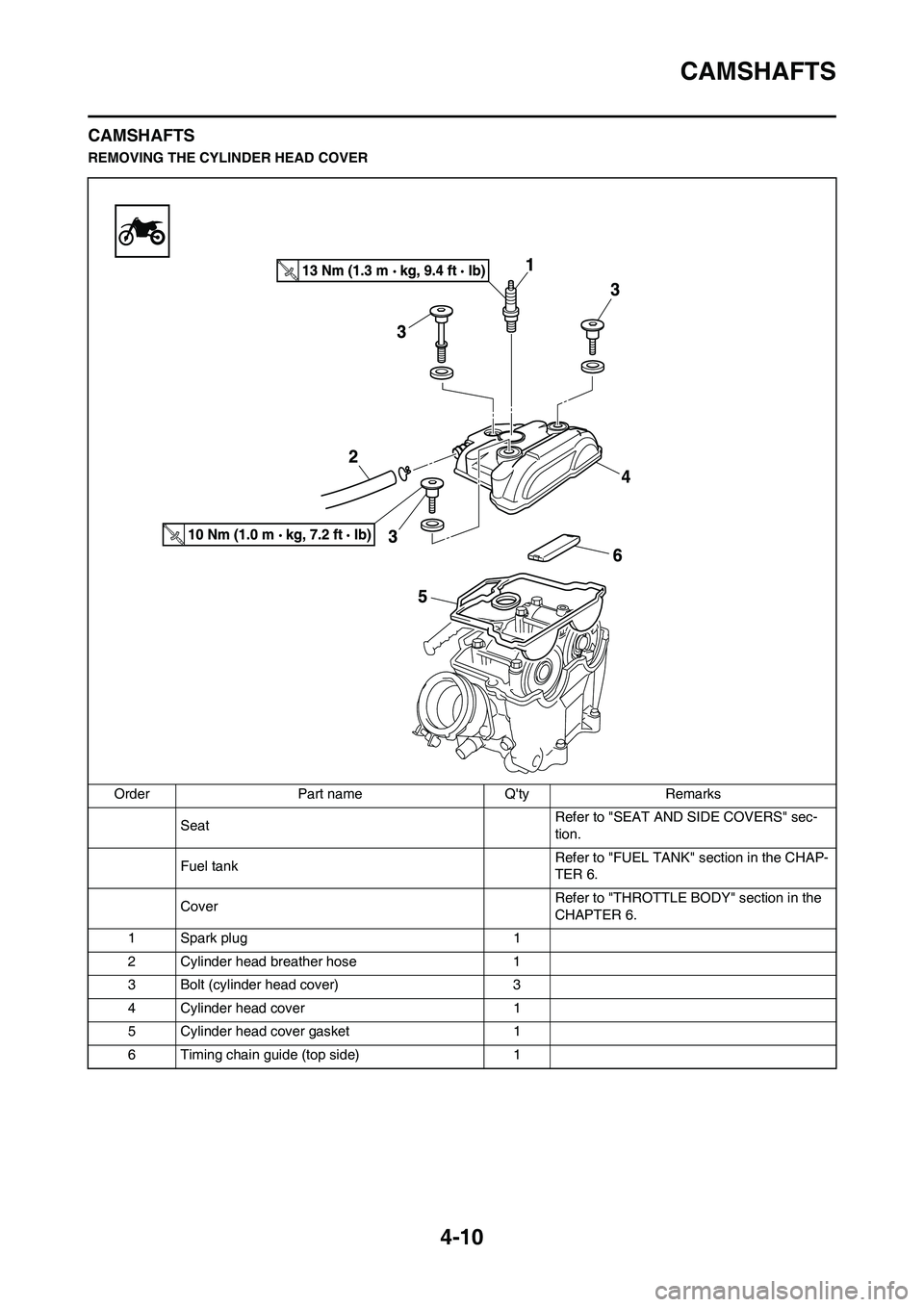
4-10
CAMSHAFTS
CAMSHAFTS
REMOVING THE CYLINDER HEAD COVER
Order Part name Q'ty Remarks
Seat Refer to "SEAT AND SIDE COVERS" sec-
tion.
Fuel tank Refer to "FUEL TANK" section in the CHAP-
TER 6.
CoverRefer to "THROTTLE BODY" section in the
CHAPTER 6.
1 Spark plug 1
2 Cylinder head breather hose 1
3 Bolt (cylinder head cover) 3
4 Cylinder head cover 1
5 Cylinder head cover gasket 1
6 Timing chain guide (top side) 1
Page 92 of 230
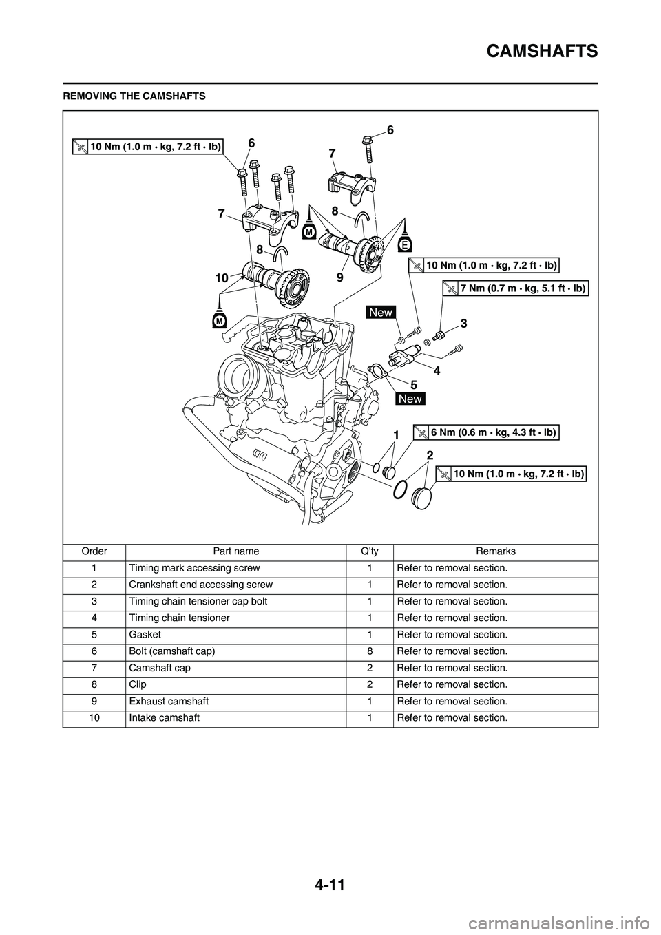
4-11
CAMSHAFTS
REMOVING THE CAMSHAFTS
Order Part name Q'ty Remarks
1 Timing mark accessing screw1 Refer to removal section.
2 Crankshaft end accessing screw 1 Refer to removal section.
3 Timing chain tensioner cap bolt 1 Refer to removal section.
4 Timing chain tensioner 1 Refer to removal section.
5 Gasket 1 Refer to removal section.
6 Bolt (camshaft cap) 8 Refer to removal section.
7 Camshaft cap 2 Refer to removal section.
8 Clip 2 Refer to removal section.
9 Exhaust camshaft 1 Refer to removal section.
10 Intake camshaft 1 Refer to removal section.
Page 93 of 230
4-12
CAMSHAFTS
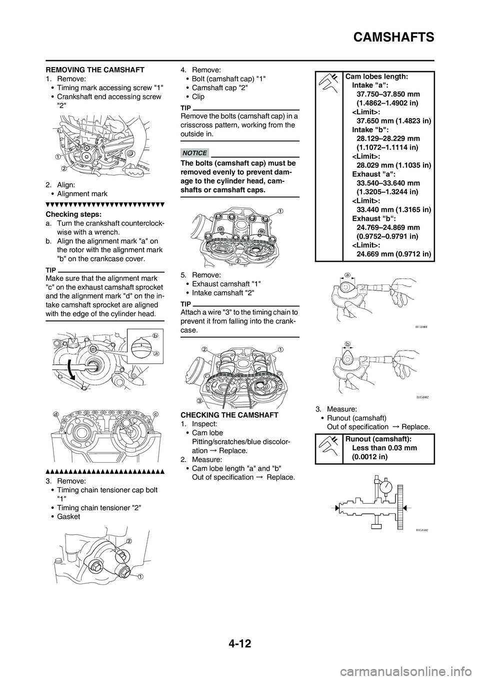
REMOVING THE CAMSHAFT
1. Remove:
• Timing mark accessing screw "1"
• Crankshaft end accessing screw
"2"
2. Align:
• Alignment mark
Checking steps:
a. Turn the crankshaft counterclock-
wise with a wrench.
b. Align the alignment mark "a" on
the rotor with the alignment mark
"b" on the crankcase cover.
Make sure that the alignment mark
"c" on the exhaust camshaft sprocket
and the alignment mark "d" on the in-
take camshaft sprocket are aligned
with the edge of the cylinder head.
3. Remove:
• Timing chain tensioner cap bolt
"1"
• Timing chain tensioner "2"
• Gasket4. Remove:
• Bolt (camshaft cap) "1"
• Camshaft cap "2"
• Clip
Remove the bolts (camshaft cap) in a
crisscross pattern, working from the
outside in.
The bolts (camshaft cap) must be
removed evenly to prevent dam-
age to the cylinder head, cam-
shafts or camshaft caps.
5. Remove:
• Exhaust camshaft "1"
• Intake camshaft "2"
Attach a wire "3" to the timing chain to
prevent it from falling into the crank-
case.
CHECKING THE CAMSHAFT
1. Inspect:
• Cam lobe
Pitting/scratches/blue discolor-
ation → Replace.
2. Measure:
• Cam lobe length "a" and "b"
Out of specification → Replace.3. Measure:
• Runout (camshaft)
Out of specification → Replace.
Cam lobes length:
Intake "a":
37.750–37.850 mm
(1.4862–1.4902 in)
37.650 mm (1.4823 in)
Intake "b":
28.129–28.229 mm
(1.1072–1.1114 in)
28.029 mm (1.1035 in)
Exhaust "a":
33.540–33.640 mm
(1.3205–1.3244 in)
33.440 mm (1.3165 in)
Exhaust "b":
24.769–24.869 mm
(0.9752–0.9791 in)
24.669 mm (0.9712 in)
Runout (camshaft):
Less than 0.03 mm
(0.0012 in)
Page 94 of 230
4-13
CAMSHAFTS
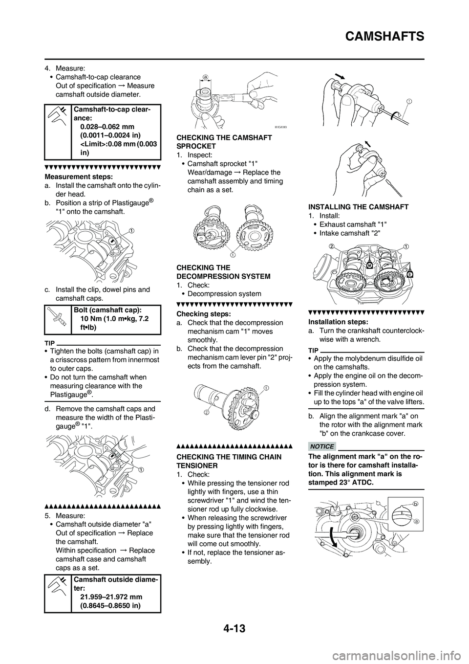
4. Measure:• Camshaft-to-cap clearanceOut of specification → Measure
camshaft outside diameter.
Measurement steps:
a. Install the camshaft onto the cylin- der head.
b. Position a strip of Plastigauge
®
"1" onto the camshaft.
c. Install the clip, dowel pins and camshaft caps.
• Tighten the bolts (camshaft cap) in a crisscross pattern from innermost
to outer caps.
• Do not turn the camshaft when
measuring clearance with the
Plastigauge
®.
d. Remove the camshaft caps and measure the width of the Plasti-
gauge
® "1".
5. Measure:• Camshaft outside diameter "a"
Out of specification → Replace
the camshaft.
Within specification → Replace
camshaft case and camshaft
caps as a set. CHECKING THE CAMSHAFT
SPROCKET
1. Inspect:
• Camshaft sprocket "1"Wear/damage →Replace the
camshaft assemb ly and timing
chain as a set.
CHECKING THE
DECOMPRESSION SYSTEM
1. Check: • Decompression system
Checking steps:
a. Check that the decompression
mechanism cam "1" moves
smoothly.
b. Check that the decompression
mechanism cam lever pin "2" proj-
ects from the camshaft.
CHECKING THE TIMING CHAIN
TENSIONER
1. Check:• While pressing the tensioner rod lightly with fingers, use a thin
screwdriver "1" and wind the ten-
sioner rod up fully clockwise.
• When releasing the screwdriver
by pressing lightly with fingers,
make sure that the tensioner rod
will come out smoothly.
• If not, replace the tensioner as- sembly. INSTALLING THE CAMSHAFT
1. Install:
• Exhaust camshaft "1"
• Intake camshaft "2"
Installation steps:
a. Turn the crankshaft counterclock- wise with a wrench.
• Apply the molybdenum disulfide oil on the camshafts.
• Apply the engine oil on the decom- pression system.
• Fill the cylinder head with engine oil
up to the tops "a" of the valve lifters.
b. Align the alignment mark "a" on the rotor with the alignment mark
"b" on the crankcase cover.
The alignment mark "a" on the ro-
tor is there for camshaft installa-
tion. This alignment mark is
stamped 23° ATDC.
Camshaft-to-cap clear-
ance:
0.028–0.062 mm
(0.0011–0.0024 in)
in)
Bolt (camshaft cap): 10 Nm (1.0 m•kg, 7.2
ft•lb)
Camshaft outside diame-
ter: 21.959–21.972 mm
(0.8645–0.8650 in)
Page 95 of 230
4-14
CAMSHAFTS
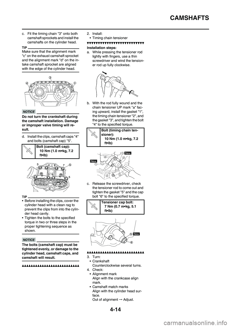
c. Fit the timing chain "3" onto both camshaft sprockets and install the
camshafts on the cylinder head.
Make sure that the alignment mark
"c" on the exhaust camshaft sprocket
and the alignment mark "d" on the in-
take camshaft sprocket are aligned
with the edge of the cylinder head.
Do not turn the crankshaft during
the camshaft insta llation. Damage
or improper valve timing will re-
sult.
d. Install the clips, camshaft caps "4"
and bolts (camshaft cap) "5".
• Before installing the clips, cover the cylinder head with a clean rag to
prevent the clips from into the cylin-
der head cavity.
• Tighten the bolts to the specified
torque in two or three steps in the
proper tightening sequence as
shown.
The bolts (camshaft cap) must be
tightened evenly, or damage to the
cylinder head, camshaft caps, and
camshaft will result.
2. Install:• Timing chain tensioner
Installation steps:
a. While pressing the tensioner rod lightly with fingers, use a thin
screwdriver and wind the tension-
er rod up fully clockwise.
b. With the rod fully wound and the chain tensioner UP mark "a" fac-
ing upward, install the gasket "1",
the timing chain tensioner "2", and
the gasket "3", and tighten the bolt
"4" to the specified torque.
c. Release the screwdriver, check the tensioner rod to come out and
tighten the gasket "5" and the cap
bolt "6" to the specified torque.
3. Turn:• Crankshaft
Counterclockwise several turns.
4. Check: • Alignment mark
Align with the crankcase align
mark.
• Camshaft match marks
Align with the cylinder head sur-
face.
Out of alignment →Adjust.
Bolt (camshaft cap):
10 Nm (1.0 m•kg, 7.2
ft•lb)
Bolt (timing chain ten-
sioner):10 Nm (1.0 m•kg, 7.2
ft•lb)
Tensioner cap bolt: 7 Nm (0.7 m•kg, 5.1
ft•lb)
Page 96 of 230
4-15
CYLINDER HEAD
CYLINDER HEAD
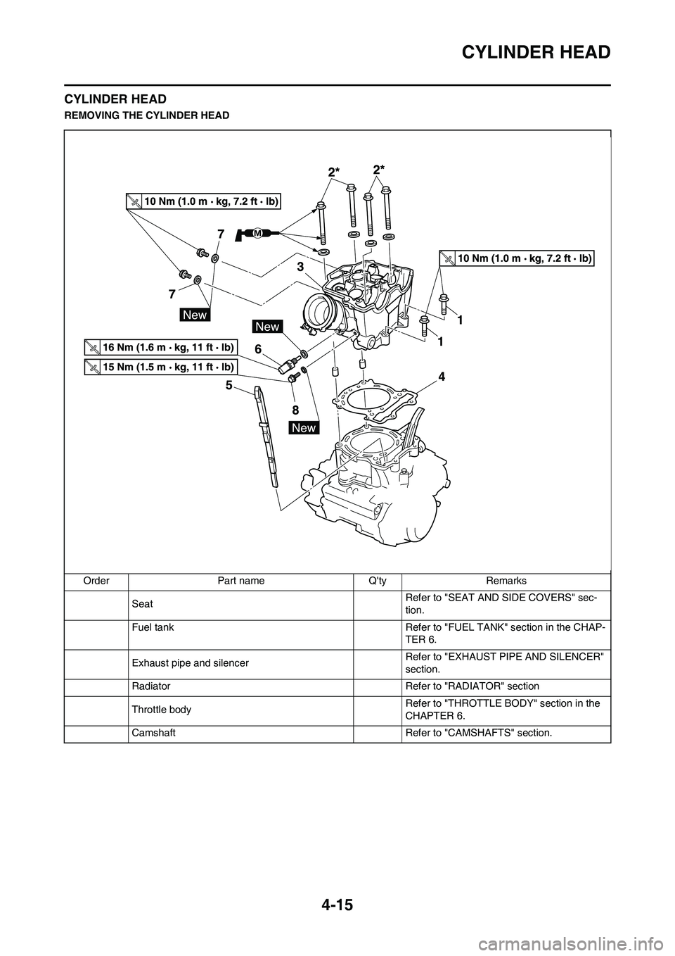
REMOVING THE CYLINDER HEAD
Order Part name Q'ty Remarks
SeatRefer to "SEAT AND SIDE COVERS" sec-
tion.
Fuel tank Refer to "FUEL TANK" section in the CHAP-
TER 6.
Exhaust pipe and silencerRefer to "EXHAUST PIPE AND SILENCER"
section.
Radiator Refer to "RADIATOR" section
Throttle body Refer to "THROTTLE BODY" section in the
CHAPTER 6.
Camshaft Refer to "CAMSHAFTS" section.
Page 97 of 230
4-16
CYLINDER HEAD
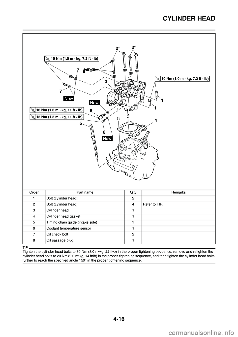
Tighten the cylinder head bolts to 30 Nm (3.0 m•kg, 22 ft•b) in the proper tightening sequence, remove and retighten the
cylinder head bolts to 20 Nm (2.0 m•kg, 14 ft•lb) in the proper tightening sequence, and then tighten the cylinder head bolts
further to reach the specified angle 150° in the proper tightening sequence.
1 Bolt (cylinder head) 2
2 Bolt (cylinder head) 4 Refer to TIP.
3 Cylinder head 1
4 Cylinder head gasket 1
5 Timing chain guide (intake side) 1
6 Coolant temperature sensor 1
7 Oil check bolt 2
8 Oil passage plug 1 Order Part name Q'ty Remarks
Page 98 of 230
4-17
CYLINDER HEAD
CHECKING THE CYLINDER HEAD
1. Eliminate:
• Carbon deposits (from the com-
bustion chambers)
Use a rounded scraper.
Do not use a sharp instrument to
avoid damaging or scratching:
• Spark plug threads
• Valve seats
2. Inspect:
• Cylinder head
Scratches/damage → Replace.
Replace the titanium valves with the
cylinder head.
Refer to"CHECKING THE VALVE".
3. Measure:
• Cylinder head warpage
Out of specification → Resur-
face.
Warpage measurement and resur-
facing steps:
a. Place a straightedge and a feeler
gauge across the cylinder head.
b. Use a feeler gauge to measure
the warpage.
c. If the warpage is out of specifica-
tion, resurface the cylinder head.
d. Place a 400–600 grit wet sandpa-
per on the surface plate, and re-
surface the head using a figure-
eight sanding pattern.
To ensure an even surface rotate the
cylinder head several times.
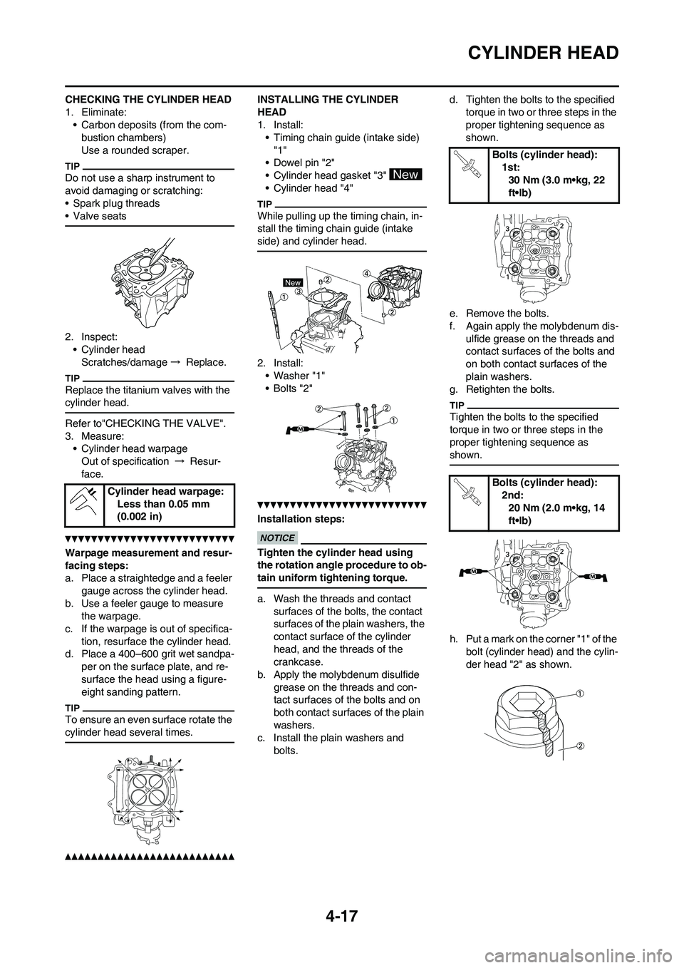
INSTALLING THE CYLINDER
HEAD
1. Install:
• Timing chain guide (intake side)
"1"
• Dowel pin "2"
• Cylinder head gasket "3"
• Cylinder head "4"
While pulling up the timing chain, in-
stall the timing chain guide (intake
side) and cylinder head.
2. Install:
• Washer "1"
• Bolts "2"
Installation steps:
Tighten the cylinder head using
the rotation angle procedure to ob-
tain uniform tightening torque.
a. Wash the threads and contact
surfaces of the bolts, the contact
surfaces of the plain washers, the
contact surface of the cylinder
head, and the threads of the
crankcase.
b. Apply the molybdenum disulfide
grease on the threads and con-
tact surfaces of the bolts and on
both contact surfaces of the plain
washers.
c. Install the plain washers and
bolts.d. Tighten the bolts to the specified
torque in two or three steps in the
proper tightening sequence as
shown.
e. Remove the bolts.
f. Again apply the molybdenum dis-
ulfide grease on the threads and
contact surfaces of the bolts and
on both contact surfaces of the
plain washers.
g. Retighten the bolts.
Tighten the bolts to the specified
torque in two or three steps in the
proper tightening sequence as
shown.
h. Put a mark on the corner "1" of the
bolt (cylinder head) and the cylin-
der head "2" as shown. Cylinder head warpage:
Less than 0.05 mm
(0.002 in)
Bolts (cylinder head):
1st:
30 Nm (3.0 m•kg, 22
ft•lb)
Bolts (cylinder head):
2nd:
20 Nm (2.0 m•kg, 14
ft•lb)
Page 99 of 230
4-18
CYLINDER HEAD
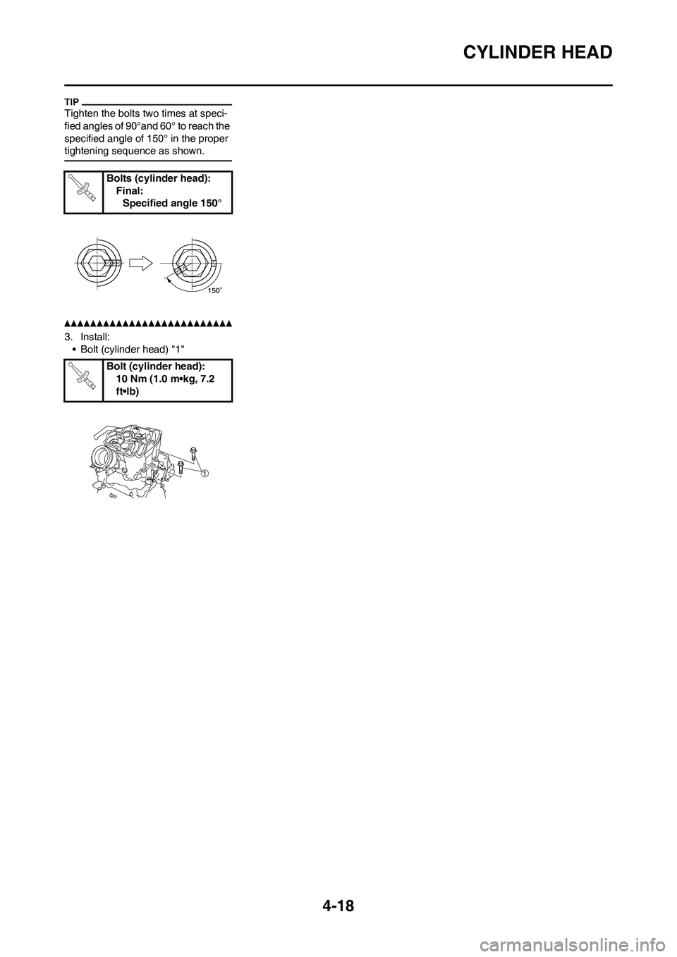
Tighten the bolts two times at speci-
fied angles of 90°and 60° to reach the
specified angle of 150° in the proper
tightening sequence as shown.
3. Install:
• Bolt (cylinder head) "1"Bolts (cylinder head):
Final:
Specified angle 150°
Bolt (cylinder head):
10 Nm (1.0 m•kg, 7.2
ft•lb)
Page 100 of 230
4-19
VALVES AND VALVE SPRINGS
VALVES AND VALVE SPRINGS
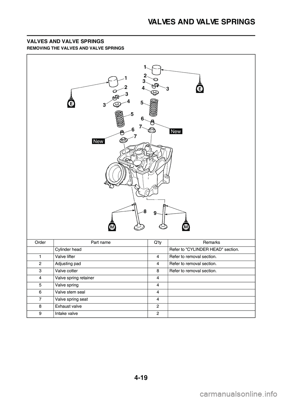
REMOVING THE VALVES AND VALVE SPRINGS
Order Part name Q'ty Remarks
Cylinder head Refer to "CYLINDER HEAD" section.
1 Valve lifter 4 Refer to removal section.
2 Adjusting pad 4 Refer to removal section.
3 Valve cotter 8 Refer to removal section.
4 Valve spring retainer 4
5 Valve spring 4
6 Valve stem seal 4
7 Valve spring seat 4
8 Exhaust valve 2
9 Intake valve 2