YAMAHA YZF-R6 2000 Owner's Manual
Manufacturer: YAMAHA, Model Year: 2000, Model line: YZF-R6, Model: YAMAHA YZF-R6 2000Pages: 111, PDF Size: 11.91 MB
Page 21 of 111
INSTRUMENT AND CONTROL FUNCTIONS
3-7
3
EAU01601
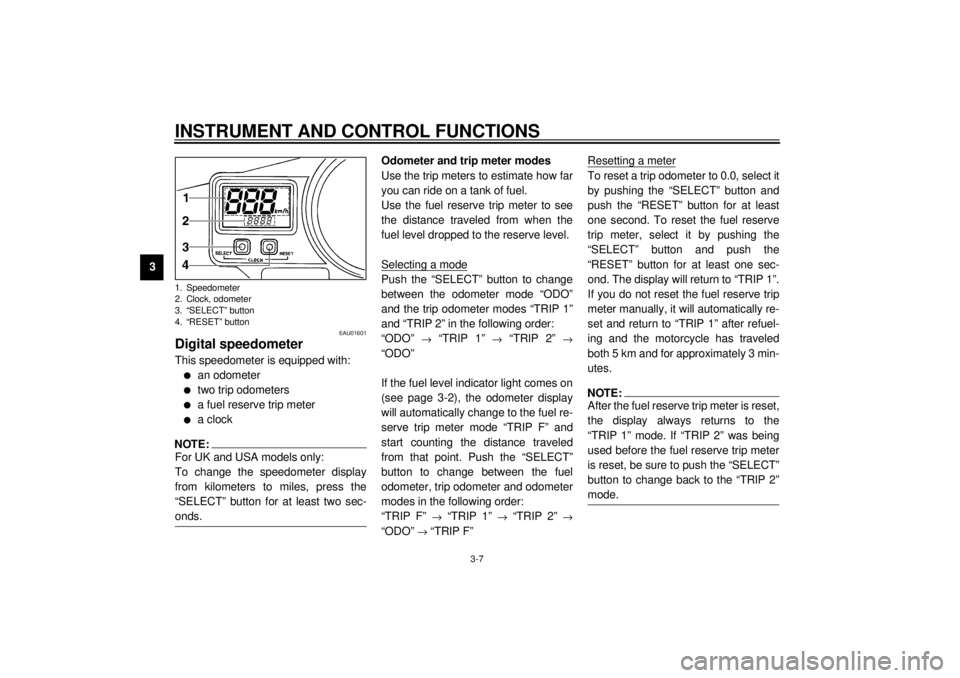
Digital speedometerThis speedometer is equipped with:l
an odometer
l
two trip odometers
l
a fuel reserve trip meter
l
a clock
NOTE:@ For UK and USA models only:
To change the speedometer display
from kilometers to miles, press the
“SELECT” button for at least two sec-
onds. @
Odometer and trip meter modes
Use the trip meters to estimate how far
you can ride on a tank of fuel.
Use the fuel reserve trip meter to see
the distance traveled from when the
fuel level dropped to the reserve level.
Selecting a modePush the “SELECT” button to change
between the odometer mode “ODO”
and the trip odometer modes “TRIP 1”
and “TRIP 2” in the following order:
“ODO”
® “TRIP 1”
® “TRIP 2”
®
“ODO”
If the fuel level indicator light comes on
(see page 3-2), the odometer display
will automatically change to the fuel re-
serve trip meter mode “TRIP F” and
start counting the distance traveled
from that point. Push the “SELECT”
button to change between the fuel
odometer, trip odometer and odometer
modes in the following order:
“TRIP F”
® “TRIP 1”
® “TRIP 2”
®
“ODO”
® “TRIP F”Resetting a meter
To reset a trip odometer to 0.0, select it
by pushing the “SELECT” button and
push the “RESET” button for at least
one second. To reset the fuel reserve
trip meter, select it by pushing the
“SELECT” button and push the
“RESET” button for at least one sec-
ond. The display will return to “TRIP 1”.
If you do not reset the fuel reserve trip
meter manually, it will automatically re-
set and return to “TRIP 1” after refuel-
ing and the motorcycle has traveled
both 5 km and for approximately 3 min-
utes.NOTE:@ After the fuel reserve trip meter is reset,
the display always returns to the
“TRIP 1” mode. If “TRIP 2” was being
used before the fuel reserve trip meter
is reset, be sure to push the “SELECT”
button to change back to the “TRIP 2”
mode. @
1. Speedometer
2. Clock, odometer
3. “SELECT” button
4. “RESET” buttonE_5eb_Functions.fm Page 7 Thursday, November 18, 1999 4:03 PM
Page 22 of 111
INSTRUMENT AND CONTROL FUNCTIONS
3-8
3 Clock mode
To change the display to the clock
mode, push both the “SELECT” and
“RESET” buttons.
To change the display back to the
odometer mode, push the “RESET”
button.
To set the clock
1. Push both the “SELECT” and
“RESET” buttons for at least two
seconds.
2. When the hour digits start flashing,
push the “RESET” button to set
the hours.
3. Push the “SELECT” button to
change the minutes.
4. When the minute digits start flash-
ing, push the “RESET” button to
set the minutes.
5. Push the “SELECT” button to start
the clock.
NOTE:@ After setting the clock, be sure to push
the “SELECT” button before turning the
main switch to “OFF”, otherwise the
clock will not be set. @
EAU00101
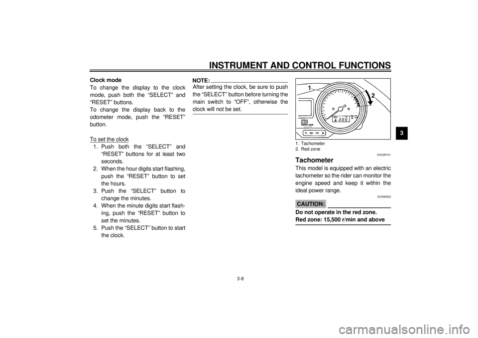
TachometerThis model is equipped with an electric
tachometer so the rider can monitor the
engine speed and keep it within the
ideal power range.
EC000003
CAUTION:@ Do not operate in the red zone.
Red zone: 15,500 r/min and above @1. Tachometer
2. Red zone
E_5eb_Functions.fm Page 8 Thursday, November 18, 1999 4:03 PM
Page 23 of 111
INSTRUMENT AND CONTROL FUNCTIONS
3-9
3
EAU00105
Diagnosis deviceThis model is equipped with a self diag-
nosis for the following circuits:l
Throttle Position Sensor (T.P.S.)
circuit
l
Fuel indicator light circuit
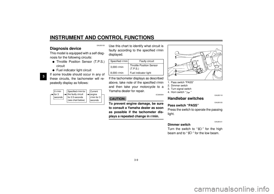
If some trouble should occur in any of
these circuits, the tachometer will re-
peatedly display as follows:
CB-53E
Use this chart to identify what circuit is
faulty according to the specified r/min
displayed.CB-60EIf the tachometer displays as described
above, take note of the specified r/min
and then take your motorcycle to a
Yamaha dealer for repair.
EC000004
CAUTION:@ To prevent engine damage, be sure
to consult a Yamaha dealer as soon
as possible if the tachometer dis-
plays a repeated change in r/min. @
EAU00118
Handlebar switches
EAU00120
Pass switch “PASS”
Press the switch to operate the passing
light.
EAU00121
Dimmer switch
Turn the switch to “ ” for the high
beam and to “ ” for the low beam.
0 r/min
for 3
seconds
Specified r/min for
the faulty circuit
for 2.5 seconds
(see chart below)
Current
engine
r/min for 3
seconds
Specified r/min
Faulty circuit
3,000 r/min
Throttle Position Sensor
(T.P.S.)
8,000 r/min
Fuel indicator light
1. Pass switch “PASS”
2. Dimmer switch
3. Turn signal switch
4. Horn switch “ ”
E_5eb_Functions.fm Page 9 Thursday, November 18, 1999 4:03 PM
Page 24 of 111
INSTRUMENT AND CONTROL FUNCTIONS
3-10
3
EAU00127
Turn signal switch
To signal a right-hand turn, push the
switch to “ ”. To signal a left-hand
turn, push the switch to “ ”. Once the
switch is released it will return to the
center position. To cancel the signal,
push the switch in after it has returned
to the center position.
EAU00129
Horn switch “ ”
Press the switch to sound the horn.
EAU00138
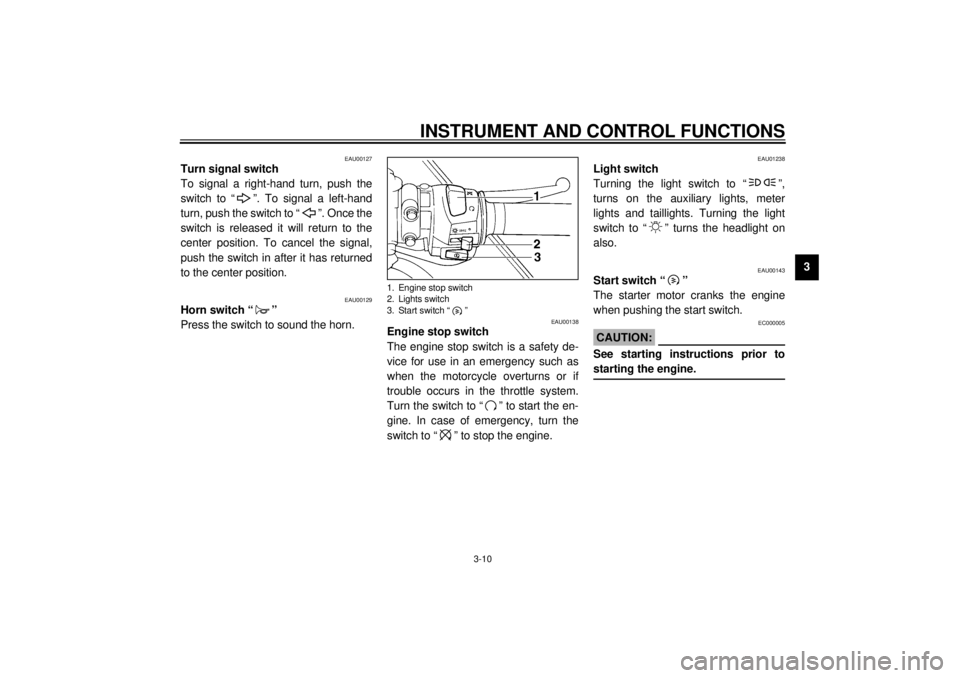
Engine stop switch
The engine stop switch is a safety de-
vice for use in an emergency such as
when the motorcycle overturns or if
trouble occurs in the throttle system.
Turn the switch to “ ” to start the en-
gine. In case of emergency, turn the
switch to “ ” to stop the engine.
EAU01238
Light switch
Turning the light switch to “ ”,
turns on the auxiliary lights, meter
lights and taillights. Turning the light
switch to “ ” turns the headlight on
also.
EAU00143
Start switch “ ”
The starter motor cranks the engine
when pushing the start switch.
EC000005
CAUTION:@ See starting instructions prior to
starting the engine. @
1. Engine stop switch
2. Lights switch
3. Start switch “ ”
E_5eb_Functions.fm Page 10 Thursday, November 18, 1999 4:03 PM
Page 25 of 111
INSTRUMENT AND CONTROL FUNCTIONS
3-11
3
EAU00152
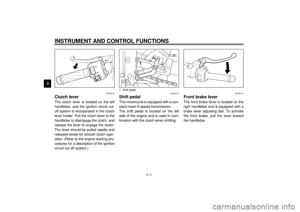
Clutch leverThe clutch lever is located on the left
handlebar, and the ignition circuit cut-
off system is incorporated in the clutch
lever holder. Pull the clutch lever to the
handlebar to disengage the clutch, and
release the lever to engage the clutch.
The lever should be pulled rapidly and
released slowly for smooth clutch oper-
ation. (Refer to the engine starting pro-
cedures for a description of the ignition
circuit cut-off system.)
EAU00157
Shift pedalThis motorcycle is equipped with a con-
stant-mesh 6-speed transmission.
The shift pedal is located on the left
side of the engine and is used in com-
bination with the clutch when shifting.
EAU00161
Front brake leverThe front brake lever is located on the
right handlebar and is equipped with a
brake lever adjusting dial. To activate
the front brake, pull the lever toward
the handlebar.
1. Shift pedal
E_5eb_Functions.fm Page 11 Thursday, November 18, 1999 4:03 PM
Page 26 of 111
INSTRUMENT AND CONTROL FUNCTIONS
3-12
3
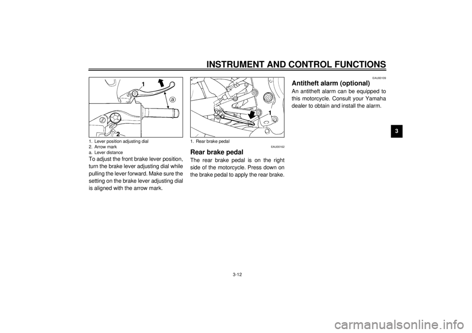
To adjust the front brake lever position,
turn the brake lever adjusting dial while
pulling the lever forward. Make sure the
setting on the brake lever adjusting dial
is aligned with the arrow mark.
EAU00162
Rear brake pedalThe rear brake pedal is on the right
side of the motorcycle. Press down on
the brake pedal to apply the rear brake.
EAU00109
Antitheft alarm (optional)An antitheft alarm can be equipped to
this motorcycle. Consult your Yamaha
dealer to obtain and install the alarm.
1. Lever position adjusting dial
2. Arrow mark
a. Lever distance
1. Rear brake pedal
E_5eb_Functions.fm Page 12 Thursday, November 18, 1999 4:03 PM
Page 27 of 111
INSTRUMENT AND CONTROL FUNCTIONS
3-13
3
EAU02935
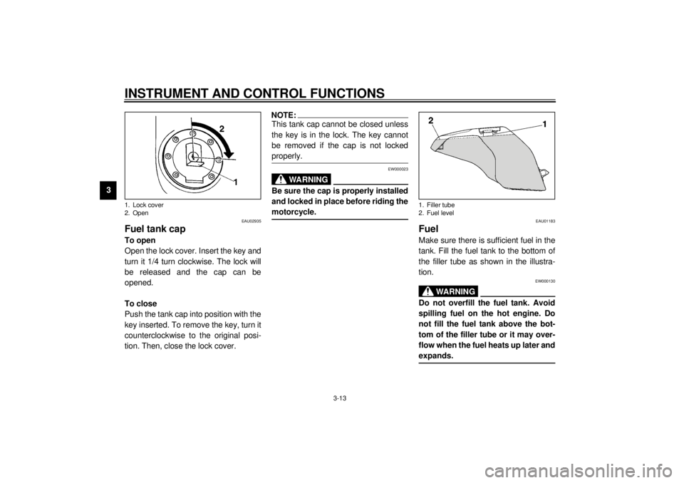
Fuel tank capTo open
Open the lock cover. Insert the key and
turn it 1/4 turn clockwise. The lock will
be released and the cap can be
opened.
To close
Push the tank cap into position with the
key inserted. To remove the key, turn it
counterclockwise to the original posi-
tion. Then, close the lock cover.
NOTE:@ This tank cap cannot be closed unless
the key is in the lock. The key cannot
be removed if the cap is not locked
properly. @
EW000023
WARNING
@ Be sure the cap is properly installed
and locked in place before riding the
motorcycle. @
EAU01183
FuelMake sure there is sufficient fuel in the
tank. Fill the fuel tank to the bottom of
the filler tube as shown in the illustra-
tion.
EW000130
WARNING
@ Do not overfill the fuel tank. Avoid
spilling fuel on the hot engine. Do
not fill the fuel tank above the bot-
tom of the filler tube or it may over-
flow when the fuel heats up later and
expands. @
1. Lock cover
2. Open
1. Filler tube
2. Fuel level
E_5eb_Functions.fm Page 13 Thursday, November 18, 1999 4:03 PM
Page 28 of 111
INSTRUMENT AND CONTROL FUNCTIONS
3-14
3
EAU00185
CAUTION:@ Always wipe off spilled fuel immedi-
ately with a dry and clean soft cloth.
Fuel may deteriorate painted surfac-
es or plastic parts. @
EAU00191
NOTE:@ If knocking or pinging occurs, use a dif-
ferent brand of gasoline or higher oc-
tane grade. @
EAU02955*
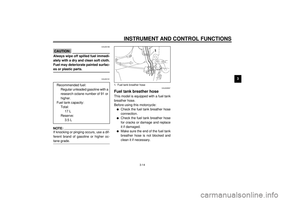
Fuel tank breather hoseThis model is equipped with a fuel tank
breather hose.
Before using this motorcycle:l
Check the fuel tank breather hose
connection.
l
Check the fuel tank breather hose
for cracks or damage and replace
it if damaged.
l
Make sure the end of the fuel tank
breather hose is not blocked and
clean it if necessary. Recommended fuel:
Regular unleaded gasoline with a
research octane number of 91 or
higher.
Fuel tank capacity:
Total:
17 L
Reserve:
3.5 L
1. Fuel tank breather hose
E_5eb_Functions.fm Page 14 Thursday, November 18, 1999 4:03 PM
Page 29 of 111
INSTRUMENT AND CONTROL FUNCTIONS
3-15
3
EAU02973
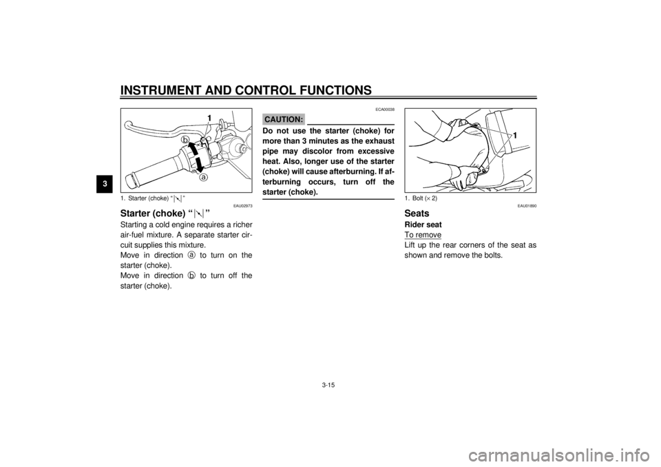
Starter (choke) “ ”Starting a cold engine requires a richer
air-fuel mixture. A separate starter cir-
cuit supplies this mixture.
Move in direction
a to turn on the
starter (choke).
Move in direction
b to turn off the
starter (choke).
ECA00038
CAUTION:@ Do not use the starter (choke) for
more than 3 minutes as the exhaust
pipe may discolor from excessive
heat. Also, longer use of the starter
(choke) will cause afterburning. If af-
terburning occurs, turn off the
starter (choke). @
EAU01890
SeatsRider seat
To removeLift up the rear corners of the seat as
shown and remove the bolts.
1. Starter (choke) “ ”
1. Bolt (´ 2)
E_5eb_Functions.fm Page 15 Thursday, November 18, 1999 4:03 PM
Page 30 of 111
INSTRUMENT AND CONTROL FUNCTIONS
3-16
3
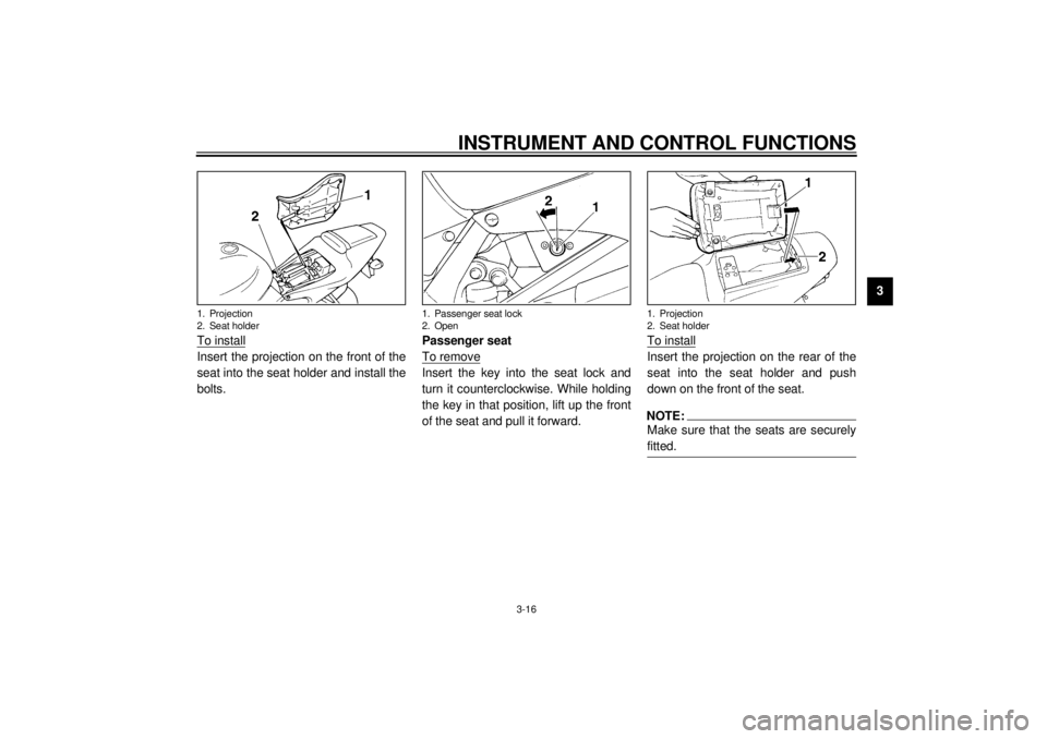
To install
Insert the projection on the front of the
seat into the seat holder and install the
bolts.Passenger seat
To remove
Insert the key into the seat lock and
turn it counterclockwise. While holding
the key in that position, lift up the front
of the seat and pull it forward.To install
Insert the projection on the rear of the
seat into the seat holder and push
down on the front of the seat.NOTE:@ Make sure that the seats are securely
fitted. @
1. Projection
2. Seat holder
1. Passenger seat lock
2. Open
1. Projection
2. Seat holder
E_5eb_Functions.fm Page 16 Thursday, November 18, 1999 4:03 PM