YAMAHA YZF-R7 1999 Repair Manual
YZF-R7 1999
YAMAHA
YAMAHA
https://www.carmanualsonline.info/img/51/54468/w960_54468-0.png
YAMAHA YZF-R7 1999 Repair Manual
Trending: check engine, oil type, low beam, oil, lights, warning light, ABS
Page 61 of 381
2 - 23
SPEC
EB202010
CHASSIS LUBRICATION POINTS AND LUBRICANT TYPES
Lubrication point Lubricant
Steering bearings and bearing races (upper and lower)
LS
Front wheel oil seal (right and left)LS
Rear wheel oil sealLS
Rear wheel drive hub oil sealLS
Rear wheel drive hub mating surfaceLS
Rear brake pedalLS
Sidestand pivoting point and metal-to-metal moving partsLS
Throttle grip inner surfaceLS
Brake lever pivoting point and metal-to-metal moving partsLS
Clutch lever pivoting point and metal-to-metal moving partsLS
Pivot shaftM
Connecting arm bearing (left and right)M
Spacer (relay arm and connecting arm)M
Oil seal (relay arm and connecting arm)M
LUBRICATION POINTS AND LUBRICANT TYPES
Page 62 of 381
2 - 24
SPEC
OIL FLOW CHART
Pressure feed
Timing chain area camshaft
Valve lifter Check bolt
Piston
Connecting rod
Big end bearing
Nozzle
Nozzle
Back torque limiter clutch
Starter clutch Main axleMain gallery
Drive axle
Oil filter cartridge
Oil cooler
Relief valve
Oil pump
Oil strainer
Oil pan
Drain bolt Main axle gears
Drive axle gearsCrankshaft journal (#2, #4)
Crankshaft journal (#3, #5)Crankshaft journal (#1)
OIL FLOW CHART
Page 63 of 381
ELECTRICAL SPECIFICATIONSSPEC
2 - 25
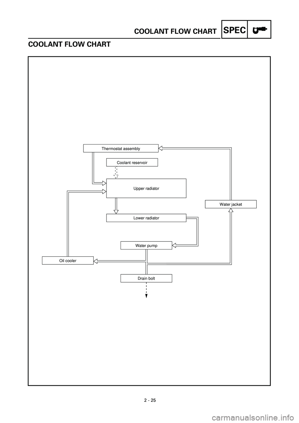
COOLANT FLOW CHART
Thermostat assembly
Coolant reservoir
Upper radiator
Lower radiator
Water pump
Drain bolt Oil coolerWater jacket
COOLANT FLOW CHART
Page 64 of 381
2 - 26
SPEC
CABLE ROUTING
1Front turn signal coupler
2Auxiliary light lead
3Headlight lead
4Throttle cable
5Left handlebar switch lead
6Clutch hose
7Front brake hose
8Right handlebar switch lead
9Main switch lead
CABLE ROUTING
Page 65 of 381
2 - 27
SPEC
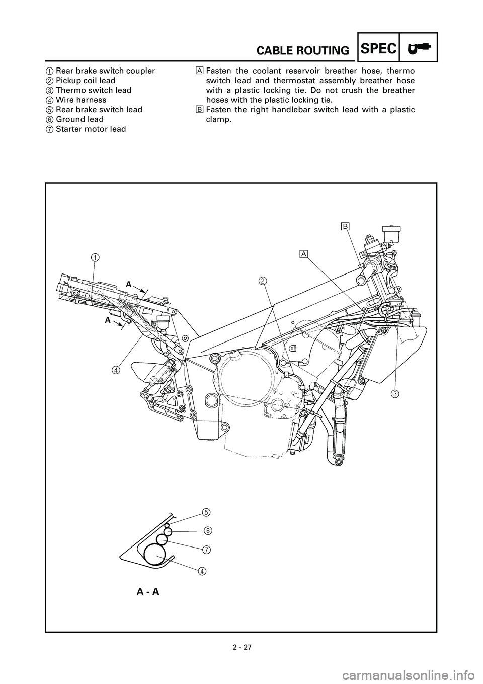
1Rear brake switch coupler
2Pickup coil lead
3Thermo switch lead
4Wire harness
5Rear brake switch lead
6Ground lead
7Starter motor leadFasten the coolant reservoir breather hose, thermo
switch lead and thermostat assembly breather hose
with a plastic locking tie. Do not crush the breather
hoses with the plastic locking tie.
õFasten the right handlebar switch lead with a plastic
clamp.
CABLE ROUTING
Page 66 of 381
2 - 28
SPEC
1Left handlebar switch lead
2Starter cable
3Main relay
4Speed sensor
5Throttle stop screw
6Sidestand switch lead
7Oil level switch lead
8Main switch lead
9Headlight and meter sub-wire har-
ness coupler0Horn lead
AHeadlight and meter sub-wire harness lead
BThrottle cable
CClutch hose
DWire harness (to headlight and meter sub-wire harness)
EWire harness
FFuel tank overflow hose
GWater pump breather hose
HCoolant reservoir breather hose
IAir filter case breather hose
CABLE ROUTING
Page 67 of 381
2 - 29
SPEC
JFuel tank breather hose
KCDI unit
LFall detection switch
MFuse box
NRelay unit
Align the portions of the main
switch lead and left handle-
bar switch lead marked with
white tape with the radiator
bracket at the frame.õFasten the starter cable and wire harness with a plastic band.
‚Fasten the oil level switch lead, speed sensor lead, sidestand
switch lead and stator coil assembly lead with a plastic band.
ëFasten the air filter breather hose, fuel tank overflow hose, clutch
hose and fuel tank breather hose with a plastic band.
ä20 mm (0.79 in)
ìRoute the sidestand switch lead behind the water pump breather
hose.
íRoute the oil level switch lead to the outside of the water pump
breather hose guide.
CABLE ROUTING
Page 68 of 381
2 - 30
SPEC
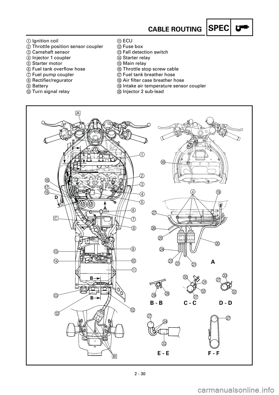
1Ignition coil
2Throttle position sensor coupler
3Camshaft sensor
4Injector 1 coupler
5Starter motor
6Fuel tank overflow hose
7Fuel pump coupler
8Rectifier/regurator
9Battery
0Turn signal relayAECU
BFuse box
CFall detection switch
DStarter relay
EMain relay
FThrottle stop screw cable
GFuel tank breather hose
HAir filter case breather hose
IIntake air temperature sensor coupler
JInjector 2 sub-lead
CABLE ROUTING
Page 69 of 381
2 - 31
SPEC
KPickup coil lead
LStator coil lead
MSpeed sensor lead
NSidestand switch lead
OOil level switch lead
PCoolant reservoir breather hose
QWire harness
RWire harness lead (to fall detection
switch coupler)
SWire harness lead (to fuse box)
TStarter motor leadUNeutral switch lead
VGround lead
WCoolant temperature sensor coupler
XThrottle cable
Route the wire harness in front of the ignition coils.
õBe sure that there is no slack in the tail/brake light lead
and rear turn signal leads below the rear fender panel.
‚Align the portions of the wire harness, ground lead and
starter motor lead marked with white tape with the lead
holder.
CABLE ROUTING
Page 70 of 381

3 - 1
CHK
ADJ
INTRODUCTION/PERIODIC MAINTENANCE AND
LUBRICATION INTERVALS
EB300000
PERIODIC CHECKS AND ADJUSTMENTS
INTRODUCTION
This chapter includes all information necessary to perform recommended checks and adjust-
ments. If followed, these preventive maintenance procedures will ensure more reliable vehi-
cle operation, a longer service life and reduce the need for costly overhaul work. This
information applies to vehicles already in service as well as to new vehicles that are being
prepared for sale. All service technicians should be familiar with this entire chapter.
PERIODIC MAINTENANCE AND LUBRICATION INTERVALS
No. ITEM CHECKS AND MAINTENANCE JOBSINITIAL
1,000 km EVERY
6,000 km or
6 months
(whichever
comes first)12,000 km or
12 months
(whichever
comes first)
1
*
Fuel line
• Check fuel hoses for cracks or damage.
• Replace if necessary.
ÖÖ
2
*
Fuel filter
• Check condition.
• Replace if necessary.
Every 50,000 km
3 Spark plugs
• Check condition.
• Clean, regap or replace if necessary.
ÖÖÖ
4
*
Valves
• Check valve clearance.
• Adjust if necessary.
Every 42,000 km or 42 months (whichever
comes first)
5 Air filter element
• Clean or replace if necessary.
ÖÖ
6 Clutch
• Check operation and fluid leakage. (See NOTE on
page 3-2.)
• Correct if necessary.
ÖÖÖ
7
*
Front brake
• Check operation, fluid level and vehicle for fluid leak-
age. (See NOTE on page 3-2.)
• Correct accordingly.
• Replace brake pads if necessary.
ÖÖÖ
8
*
Rear brake
• Check operation, fluid level and vehicle for fluid leak-
age. (See NOTE on page 3-2.)
• Correct accordingly.
• Replace brake pads if necessary.
ÖÖÖ
9
*
Wheels
• Check balance, runout and for damage.
• Rebalance or replace if necessary.
ÖÖ
10
*
Tires
• Check tread depth and for damage.
• Replace if necessary.
• Check air pressure.
• Correct if necessary.
ÖÖ
11
*
Wheel bearings
• Check bearing for looseness or damage.
• Replace if necessary.
ÖÖ
12
*
Swingarm
• Check swingarm pivoting point for play.
• Correct if necessary.
• Lubricate with lithium soap base grease every 24,000
km or 24 months (whichever comes first).
ÖÖ
13 Drive chain
• Check chain slack.
• Adjust if necessary. Make sure that the rear wheel is
properly aligned.
• Clean and lubricate.
Every 1,000 km and after washing the
motorcycle or riding in rain.
14
*
Steering bearings
• Check bearing play and steering for roughness.
• Correct accordingly.
• Lubricate with lithium soap base grease every 24,000
km or 24 months (whichever comes first).
ÖÖ
3
Trending: brake fluid, lights, oil filter, lug pattern, key battery, fuse diagram, fuses


