technical specifications Abarth Grande Punto 2010 Owner handbook (in English)
[x] Cancel search | Manufacturer: ABARTH, Model Year: 2010, Model line: Grande Punto, Model: Abarth Grande Punto 2010Pages: 207, PDF Size: 3.01 MB
Page 56 of 207
54
SAFETY
DEVICES
CORRECT USE
OF THE CAR
WARNING
LIGHTS AND
MESSAGES
IN AN
EMERGENCY
CAR
MAINTENANCE
TECHNICAL
SPECIFICATIONS
INDEX
DASHBOARD
AND CONTROLS
CEILING LIGHTS
FRONT CEILING LIGHT WITH
SPOT LIGHTS
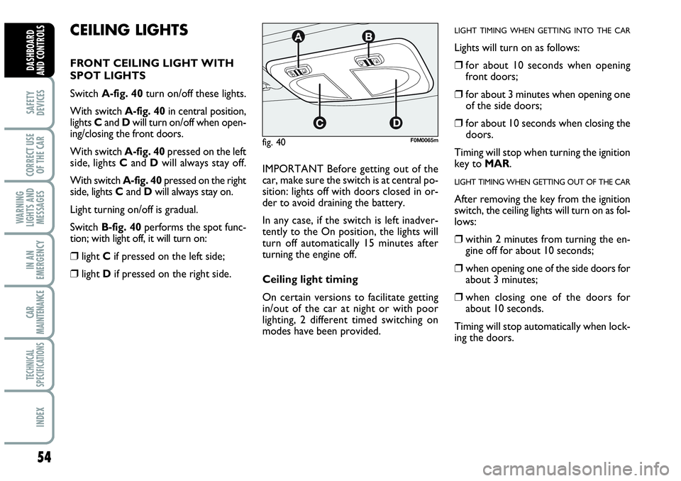
Switch A-fig. 40turn on/off these lights.
With switch A-fig. 40in central position,
lights Cand Dwill turn on/off when open-
ing/closing the front doors.
With switch A-fig. 40pressed on the left
side, lights Cand Dwill always stay off.
With switch A-fig. 40pressed on the right
side, lights Cand Dwill always stay on.
Light turning on/off is gradual.
Switch B-fig. 40performs the spot func-
tion; with light off, it will turn on:
❒light Cif pressed on the left side;
❒light Dif pressed on the right side.IMPORTANT Before getting out of the
car, make sure the switch is at central po-
sition: lights off with doors closed in or-
der to avoid draining the battery.
In any case, if the switch is left inadver-
tently to the On position, the lights will
turn off automatically 15 minutes after
turning the engine off.
Ceiling light timing
On certain versions to facilitate getting
in/out of the car at night or with poor
lighting, 2 different timed switching on
modes have been provided.
LIGHT TIMING WHEN GETTING INTO THE CAR
Lights will turn on as follows:
❒for about 10 seconds when opening
front doors;
❒for about 3 minutes when opening one
of the side doors;
❒for about 10 seconds when closing the
doors.
Timing will stop when turning the ignition
key to MAR.
LIGHT TIMING WHEN GETTING OUT OF THE CAR
After removing the key from the ignition
switch, the ceiling lights will turn on as fol-
lows:
❒within 2 minutes from turning the en-
gine off for about 10 seconds;
❒when opening one of the side doors for
about 3 minutes;
❒when closing one of the doors for
about 10 seconds.
Timing will stop automatically when lock-
ing the doors.
fig. 40F0M0065m
Page 57 of 207

55
SAFETY
DEVICES
CORRECT USE
OF THE CAR
WARNING
LIGHTS AND
MESSAGES
IIN AN
EMERGENCY
CAR
MAINTENANCE
TECHNICAL
SPECIFICATIONS
INDEX
DASHBOARD
AND CONTROLS
BOOT LIGHT fig. 41
For versions fitted with boot light, it will
turn on automatically when opening the
tailgate and it will turn off at closing.
PUDDLE LIGHTS fig. 42
These lights Aare located in the doors
and they will turn on when opening the
relevant door, regardless of the ignition
key position.
CONTROLS
HAZARD LIGHTS fig. 43
They turn on by pressing switch A, re-
gardless of the position of the ignition key.
When the device is on warning lights
Îand ¥on the cluster come on.
Press the switch again to turn the lights
off.
The use of hazard lights is governed by the
Highway Code of the country you are in.
Keep to the rules.
FRONT FOG LIGHTS fig. 44
To active, with front side lights on, press
button
5.
Warning light
5on the instrument pan-
el will turn on.
Press the button again to turn the lights
off.
The use of front fog lights is governed by
the Highway Code of the country you are
in. Keep to the rules.
fig. 41F0M0068m
fig. 42F0M0176m
fig. 43F0M073Ab
fig. 44F0M0070m
Page 58 of 207

56
SAFETY
DEVICES
CORRECT USE
OF THE CAR
WARNING
LIGHTS AND
MESSAGES
IN AN
EMERGENCY
CAR
MAINTENANCE
TECHNICAL
SPECIFICATIONS
INDEX
DASHBOARD
AND CONTROLS
HEATED REAR WINDOW fig. 47
Press button Ato turn on this function.
This function will turn off automatically af-
ter about 20 minutes. REAR FOG LIGHT fig. 45
Press button 4, to turn these lights on it
is necessary to have the dipped beam head-
lights or the front fog lights (for versions/
markets, where provided) switched on.
Warning light 4on the instrument panel
will turn on.
Press the button again to turn the light off
or turn off dipped beams and/or front fog
lights (for versions/markets, where pro-
vided).
The use of rear fog lights is governed by the
Highway Code of the country you are in.
Keep to the rules.
PARKING LIGHTS
These lights can only be turned on with ig-
nition key at STOP or removed, by mov-
ing the left stalk knurled ring first to Oand
then to
6or 2.
The warning light
3on the instrument
cluster will come on at the same time.SPORT BOOST fig. 46
Press the Abutton to start the “SPORT
BOOST” function (see “SPORT BOO-
ST” paragraph in the herein section). On-
ce this function has been started, the
“SPORT” warning light on the instru-
ment board panel turns on. Press the A
button again to switch this function off.
fig. 45F0M0071mfig. 47F0M0038mfig. 46F0M074Ab
Page 59 of 207
57
SAFETY
DEVICES
CORRECT USE
OF THE CAR
WARNING
LIGHTS AND
MESSAGES
IIN AN
EMERGENCY
CAR
MAINTENANCE
TECHNICAL
SPECIFICATIONS
INDEX
DASHBOARD
AND CONTROLS
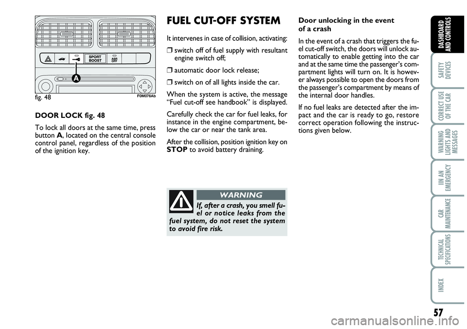
DOOR LOCK fig. 48
To lock all doors at the same time, press
button A, located on the central console
control panel, regardless of the position
of the ignition key.
FUEL CUT-OFF SYSTEM
It intervenes in case of collision, activating:
❒switch off of fuel supply with resultant
engine switch off;
❒automatic door lock release;
❒switch on of all lights inside the car.
When the system is active, the message
“Fuel cut-off see handbook” is displayed.
Carefully check the car for fuel leaks, for
instance in the engine compartment, be-
low the car or near the tank area.
After the collision, position ignition key on
STOPto avoid battery draining.
fig. 48F0M076Ab
Door unlocking in the event
of a crash
In the event of a crash that triggers the fu-
el cut-off switch, the doors will unlock au-
tomatically to enable getting into the car
and at the same time the passenger’s com-
partment lights will turn on. It is howev-
er always possible to open the doors from
the passenger’s compartment by means of
the internal door handles.
If no fuel leaks are detected after the im-
pact and the car is ready to go, restore
correct operation following the instruc-
tions given below.
If, after a crash, you smell fu-
el or notice leaks from the
fuel system, do not reset the system
to avoid fire risk.
WARNING
Page 60 of 207
58
SAFETY
DEVICES
CORRECT USE
OF THE CAR
WARNING
LIGHTS AND
MESSAGES
IN AN
EMERGENCY
CAR
MAINTENANCE
TECHNICAL
SPECIFICATIONS
INDEX
DASHBOARD
AND CONTROLS
INTERIOR FITTINGS
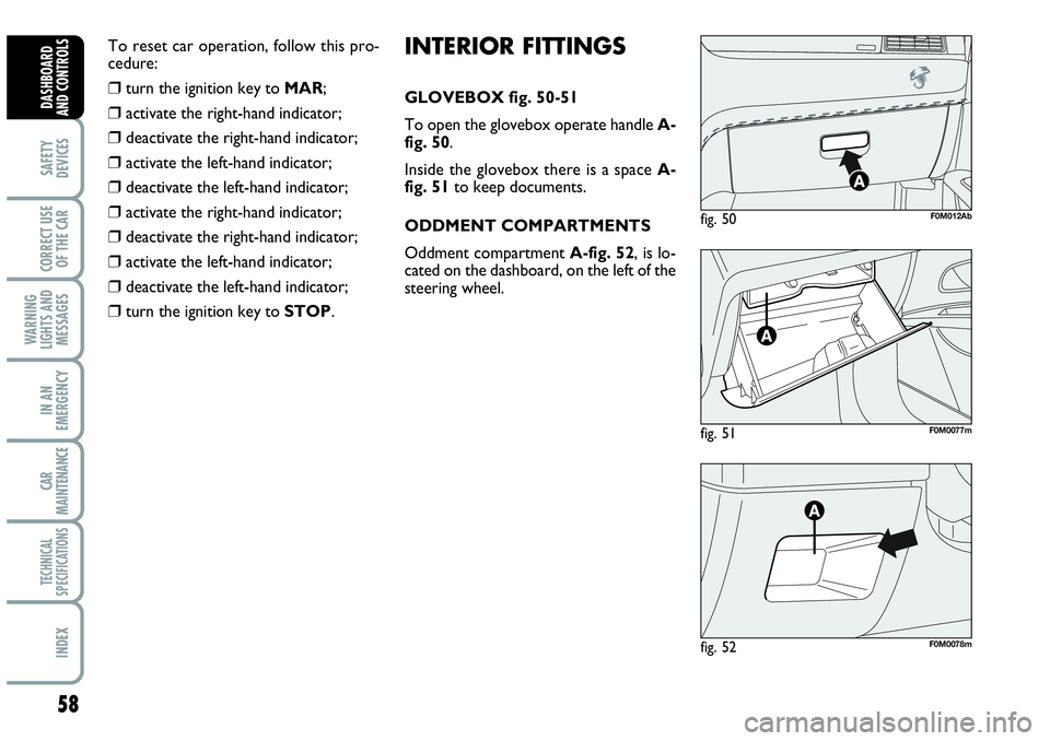
GLOVEBOX fig. 50-51
To open the glovebox operate handle A-
fig. 50.
Inside the glovebox there is a space A-
fig. 51to keep documents.
ODDMENT COMPARTMENTS
Oddment compartment A-fig. 52, is lo-
cated on the dashboard, on the left of the
steering wheel.
fig. 51F0M0077m
fig. 50F0M012Ab
fig. 52F0M0078m
To reset car operation, follow this pro-
cedure:
❒turn the ignition key to MAR;
❒activate the right-hand indicator;
❒deactivate the right-hand indicator;
❒activate the left-hand indicator;
❒deactivate the left-hand indicator;
❒activate the right-hand indicator;
❒deactivate the right-hand indicator;
❒activate the left-hand indicator;
❒deactivate the left-hand indicator;
❒turn the ignition key to STOP.
Page 61 of 207
59
SAFETY
DEVICES
CORRECT USE
OF THE CAR
WARNING
LIGHTS AND
MESSAGES
IIN AN
EMERGENCY
CAR
MAINTENANCE
TECHNICAL
SPECIFICATIONS
INDEX
DASHBOARD
AND CONTROLS
FRONT ARMREST WITH
ODDMENT COMPARTMENT
(for versions/markets,
where provided)
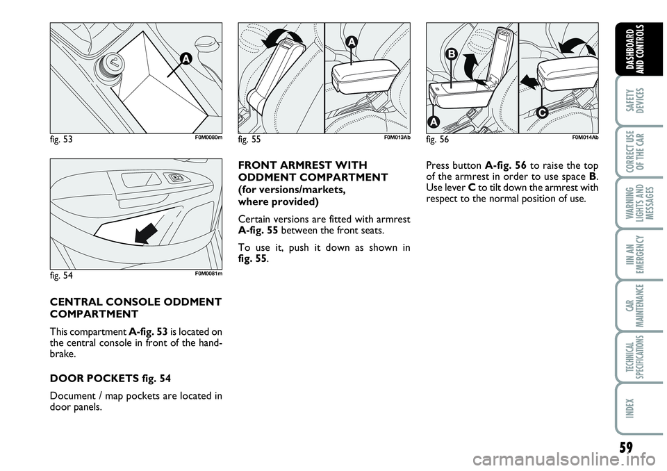
Certain versions are fitted with armrest
A-fig. 55between the front seats.
To use it, push it down as shown in
fig. 55. Press button A-fig. 56to raise the top
of the armrest in order to use space B.
Use lever Cto tilt down the armrest with
respect to the normal position of use.
CENTRAL CONSOLE ODDMENT
COMPARTMENT
This compartment A-fig. 53is located on
the central console in front of the hand-
brake.
DOOR POCKETS fig. 54
Document / map pockets are located in
door panels.
fig. 53F0M0080mfig. 55F0M013Abfig. 56F0M014Ab
fig. 54F0M0081m
Page 62 of 207
60
SAFETY
DEVICES
CORRECT USE
OF THE CAR
WARNING
LIGHTS AND
MESSAGES
IN AN
EMERGENCY
CAR
MAINTENANCE
TECHNICAL
SPECIFICATIONS
INDEX
DASHBOARD
AND CONTROLS
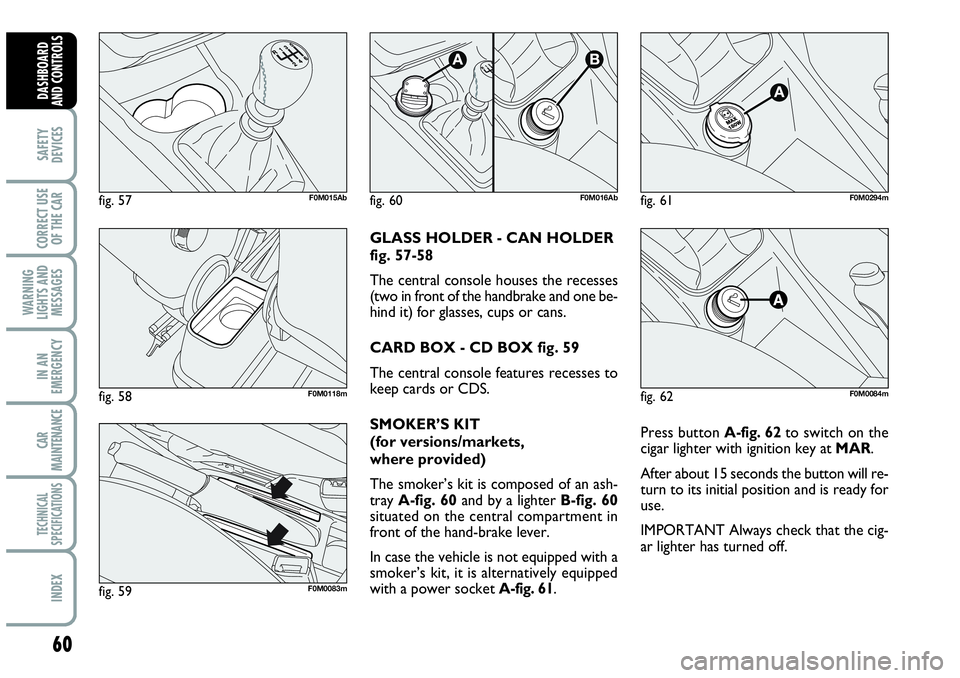
Press button A-fig. 62to switch on the
cigar lighter with ignition key at MAR.
After about 15 seconds the button will re-
turn to its initial position and is ready for
use.
IMPORTANT Always check that the cig-
ar lighter has turned off. GLASS HOLDER - CAN HOLDER
fig. 57-58
The central console houses the recesses
(two in front of the handbrake and one be-
hind it) for glasses, cups or cans.
CARD BOX - CD BOX fig. 59
The central console features recesses to
keep cards or CDS.
SMOKER’S KIT
(for versions/markets,
where provided)
The smoker’s kit is composed of an ash-
tray A-fig. 60and by a lighter B-fig. 60
situated on the central compartment in
front of the hand-brake lever.
In case the vehicle is not equipped with a
smoker’s kit, it is alternatively equipped
with a power socket A-fig. 61.
fig. 62F0M0084m
fig. 57F0M015Ab
fig. 59F0M0083m
fig. 58F0M0118m
fig. 60F0M016Abfig. 61F0M0294m
Page 63 of 207
61
SAFETY
DEVICES
CORRECT USE
OF THE CAR
WARNING
LIGHTS AND
MESSAGES
IIN AN
EMERGENCY
CAR
MAINTENANCE
TECHNICAL
SPECIFICATIONS
INDEX
DASHBOARD
AND CONTROLS
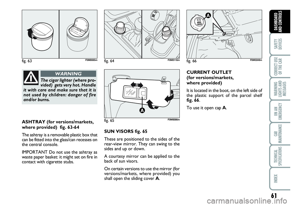
ASHTRAY (for versions/markets,
where provided) fig. 63-64
The ashtray is a removable plastic box that
can be fitted into the glass/can recesses on
the central console.
IMPORTANT Do not use the ashtray as
waste paper basket: it might set on fire in
contact with cigarette stubs.SUN VISORS fig. 65
These are positioned to the sides of the
rear-view mirror. They can swing to the
sides and up or down.
A courtesy mirror can be applied to the
back of sun visors.
On certain versions to use the mirror (for
versions/markets, where provided) you
shall open the sliding cover A.CURRENT OUTLET
(for versions/markets,
where provided)
It is located in the boot, on the left side of
the plastic support of the parcel shelf
fig. 66.
To use it open cap A.
The cigar lighter (where pro-
vided) gets very hot. Handle
it with care and make sure that it is
not used by children: danger of fire
and/or burns.
WARNING
fig. 63F0M0085m
fig. 65F0M0086m
fig. 66F0M0249mfig. 64F0M0116m
Page 64 of 207

62
SAFETY
DEVICES
CORRECT USE
OF THE CAR
WARNING
LIGHTS AND
MESSAGES
IN AN
EMERGENCY
CAR
MAINTENANCE
TECHNICAL
SPECIFICATIONS
INDEX
DASHBOARD
AND CONTROLS
SKY-DOME SUNROOF
(for versions/markets,
where provided)
The sunroof consists of two wide panes
(a fixed one and a moving one), fitted with
manually-operated sun curtains. Sun cur-
tains can be used in the “wide open” and
“wide shut” positions (fixed intermediate
positions are not provided). To open sun
curtains: take handle A-fig. 67, release it
and then guide it to the “wide open” po-
sition as shown by the arrows. To close
sun curtains reverse this procedure. Sun-
roof only works with ignition key at MAR.
Controls A-B fig. 67set near the front
ceiling light on the dedicated control pan-
el, shall be used to open/close the sunroof.
To open
Press and keep pressed button B-fig. 67,
the front pane will set to the “spoiler” po-
sition; press button B-fig. 67 again for
over half a second to make the sunroof
sliding automatically to the wide open po-
sition; press the button to stop the sun-
roof at an intermediate position.To close
When in wide open position, press but-
ton A-fig. 68for over half a second to set
the front pane to the “spoiler” position;
press the button again to stop the sunroof
at an intermediate position; press button
A-fig. 68again and keep it pressed to
close the sunroof completely.
Use the sunroof only at
“spoiler” position if cross roof
racks are fitted.
Do not open the sunroof if
there is snow or ice on it: it
could be damaged.
When leaving the car, the ig-
nition key should be removed
to prevent the sunroof from being op-
erated inadvertently and harming any-
one remaining in the car. Improper use
of the sunroof can be dangerous. Be-
fore and during its operation ensure
that any passengers are not at risk
from the moving roof either by per-
sonal objects getting caught in the
mechanism or by being injured by it di-
rectly.
WARNING
fig. 67
A
B
F0M0087mfig. 68F0M0172m
Page 65 of 207

63
SAFETY
DEVICES
CORRECT USE
OF THE CAR
WARNING
LIGHTS AND
MESSAGES
IIN AN
EMERGENCY
CAR
MAINTENANCE
TECHNICAL
SPECIFICATIONS
INDEX
DASHBOARD
AND CONTROLS
ANTI-CRUSHING SAFETY
SYSTEM
Sunroof is fitted with anti-crushing safety
system that detects the presence of an ob-
stacle during sunroof closing stroke and
that cuts in by stopping and reversing the
sunroof stroke.
INITIALISATION PROCEDURE
Sunroof shall be re-initialised after dis-
connecting the battery or if the relevant
protection fuse is blown.
Proceed as follows:
❒press button A-fig. 68at close posi-
tion;
❒keep the button pressed to close com-
pletely by steps the sunroof;
❒after full closing, wait for sunroof mo-
tor stopping.When leaving the car, the ignition key
should be removed to prevent the sun-
roof from being operated inadvertently
and harming anyone remaining in the car.
Improper use of the sunroof can be dan-
gerous. Before and during its operation
ensure that any passengers are not at risk
from the moving roof either by personal
objects getting caught in the mechanism
or by being injured by it directly.
EMERGENCY OPERATION
If the switch does not work, the sunroof
can be operated manually as follows:
❒remove the protection cap set between
the two sun curtains;
❒take the setscrew wrench (provided as
standard) from the tool bag in the boot;
❒fit the wrench into A-fig. 69and turn
it:
– clockwise to open the sunroof;
– counter-clockwise to close the sun-
roof.
fig. 69F0M0088m