lock Acura MDX 2017 Owner's Manual
[x] Cancel search | Manufacturer: ACURA, Model Year: 2017, Model line: MDX, Model: Acura MDX 2017Pages: 170, PDF Size: 12.43 MB
Page 87 of 170
80 |
Subscription Features
In addition to standard service, receive benefits such as collision notification,
emergency assistance, online security, enhanced navigation searches, and
important messages about your vehicle. Requires enrollment and privacy
agreement. To subscribe or get more information, visit owners.acura.com (U.S.) or
myacura.ca (Canada) or contact a dealer.
Emergency AssistanceIf your vehicle’s airbags deploy or if the unit detects that the vehicle is severely
impacted, your vehicle automatically attempts to connect to the AcuraLink
operator if your phone is paired to the system and there is sufficient cellular
coverage.
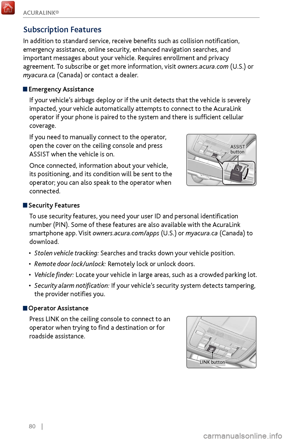
If you need to manually connect to the operator,
open the cover on the ceiling console and press
ASSIST when the vehicle is on.
Once connected, information about your vehicle,
its positioning, and its condition will be sent to the
operator; you can also speak to the operator when
connected.
Security FeaturesTo use security features, you need your user ID and personal identification
number (PIN). Some of these features are also available with the AcuraLink
smartphone app. Visit owners.acura.com/apps (U.S.) or myacura.ca (Canada) to
download.
•
Stolen
vehicle tracking: Searches and tracks down your vehicle position.
•
Remote door
lock/unlock: Remotely lock or unlock doors.
•
Vehicle finder: Locate
your vehicle in large areas, such as a crowded parking lot.
•
Security alarm
notification: If your vehicle’s security system detects tampering,
the provider notifies you.
Operator Assistance
Press LINK on the ceiling console to connect to an
operator when trying to find a destination or for
roadside assistance.
ASSIST
button
LINK button
ACURALINK®
Page 95 of 170
88 |
DRIVING
Learn about preparation for driving, as well as other features.
Before Driving
Check the following items before you begin driving.
Exterior Checks
•
Make sur
e there are no obstructions on the windows, door mirrors, exterior
lights, or other parts of the vehicle.
•
Remov
e any frost, snow, or ice.
•
Make sure
the hood is securely closed.
•
Heat from
the engine and exhaust can ignite flammable materials left under
the hood, causing a fire. If you’ve parked your vehicle for an extended period,
inspect and remove any debris that may have collected, such as dried grass
and leaves that have fallen or have been carried in for use as a nest by a small
animal. Also check under the hood for leftover flammable materials after you
or someone else has performed maintenance on your vehicle.
•
Make sure
the tires are in good condition.
•
Make sure
there are no people or objects behind or around the vehicle.
DRIVING
Interior Checks•
Store or secur
e all items on board properly.
•
Do not pile items higher than the seat height
.
•
Do not place anything in the
front seat footwells. Make sure to secure the floor
mats.
•
If you hav
e any animals on board, do not let them move freely in the vehicle.
•
Securely close and lock all
doors and the tailgate.
•
Adjust y
our seating position, mirrors, and steering wheel properly.
•
Make sure items placed
on the floor behind the front seats cannot roll under
the seats.
•
Everyone in
the vehicle must fasten their seat belt.
•
Make sure
that the indicators in the instrument panel come on when you start
the vehicle, and go off soon after.
If the doors are frozen shut, use warm water around the door edges to melt any
ice. Do not try to force them open, as this can damage the rubber trim around the
doors. When done, wipe dry to avoid further freezing.
NOTICE
Page 103 of 170
96 |
DRIVING
Remote Engine Start*
Start your vehicle’s engine from extended distances using the two-way remote
transmitter before you enter the vehicle.
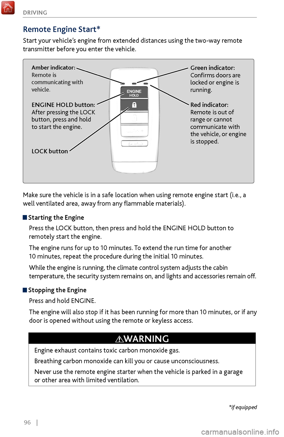
Green indicator:
Confirms doors are
locked or engine is
running.Amber indicator:
Remote is
communicating with
vehicle.
Red indicator:
Remote is out of
range or cannot
communicate with
the vehicle, or engine
is stopped.ENGINE HOLD button:
After pressing the LOCK
button, press and hold
to start the engine.
LOCK button
Make sure the vehicle is in a safe location when using remote engine start (i.e., a
well ventilated area, away from any flammable materials).
Starting the Engine
Press the LOCK button, then press and hold the ENGINE HOLD button to
remotely start the engine.
The engine runs for up to 10 minutes. To extend the run time for another
10 minutes, repeat the procedure during the initial 10 minutes.
While the engine is running, the climate control system adjusts the cabin
temperature, the security system remains on, and lights and accessories remain off.
Stopping the Engine Press and hold ENGINE.
The engine will also stop if it has been running for more than 10 minutes, or if any
door is opened without using the remote or keyless access.
Engine exhaust contains toxic carbon monoxide gas.
Breathing carbon monoxide can kill you or cause unconsciousness.
Never use the remote engine starter when the vehicle is parked in a garage
or other area with limited ventilation.
WARNING
*if equipped
Page 109 of 170
102 |
DRIVING
Braking
Slow down or stop your vehicle, and keep it from moving when parked.
Foot Brake
Press the brake pedal to slow down or stop your vehicle from moving.
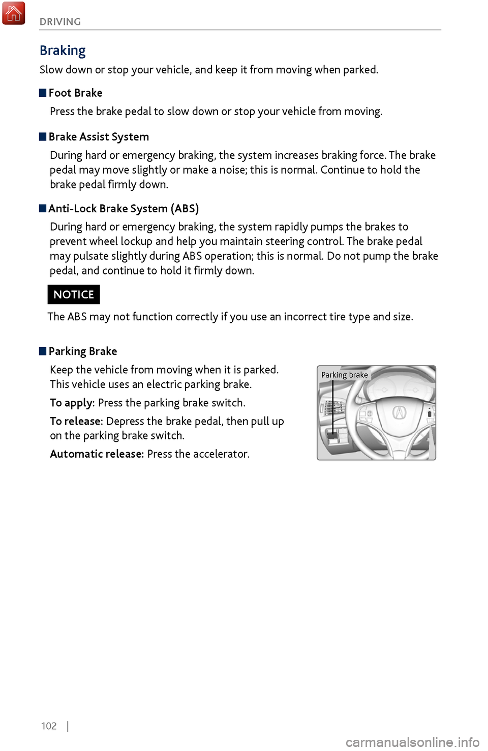
Parking BrakeKeep the vehicle from moving when it is parked.
This vehicle uses an electric parking brake.
To apply: Press the parking brake switch.
To release: Depress the brake pedal, then pull up
on the parking brake switch.
Automatic release: Press the accelerator.
Brake Assist SystemDuring hard or emergency braking, the system increases braking force. The brake
pedal may move slightly or make a noise; this is normal. Continue to hold the
brake pedal firmly down.
Anti-Lock Brake System (ABS)During hard or emergency braking, the system rapidly pumps the brakes to
prevent wheel lockup and help you maintain steering control. The brake pedal
may pulsate slightly during ABS operation; this is normal. Do not pump the brake
pedal, and continue to hold it firmly down.
The ABS may not function correctly if you use an incorrect tire type and size.
NOTICE
Parking brake
Page 128 of 170
| 121
HANDLING THE UNEXPECTED
After the Engine Starts
Once your vehicle’s engine has started, remove the jumper cables in the following
order:
1.
Disconnect the jumper cable fr
om your vehicle’s ground.
2.
Disconnect the other end
of the jumper cable from the booster battery (-)
terminal.
3.
Disconnect the jumper cable fr
om your vehicle’s battery (+) terminal.
4.
Disconnect the other end
of the jumper cable from the booster battery (+)
terminal.
5.
Have y
our vehicle inspected by a nearby service station or a dealer.
A battery can explode if you do not follow the correct procedure, seriously
injuring anyone nearby.
Keep all sparks, open flames, and smoking materials away from the battery.
WARNING
Emergency Engine Stop
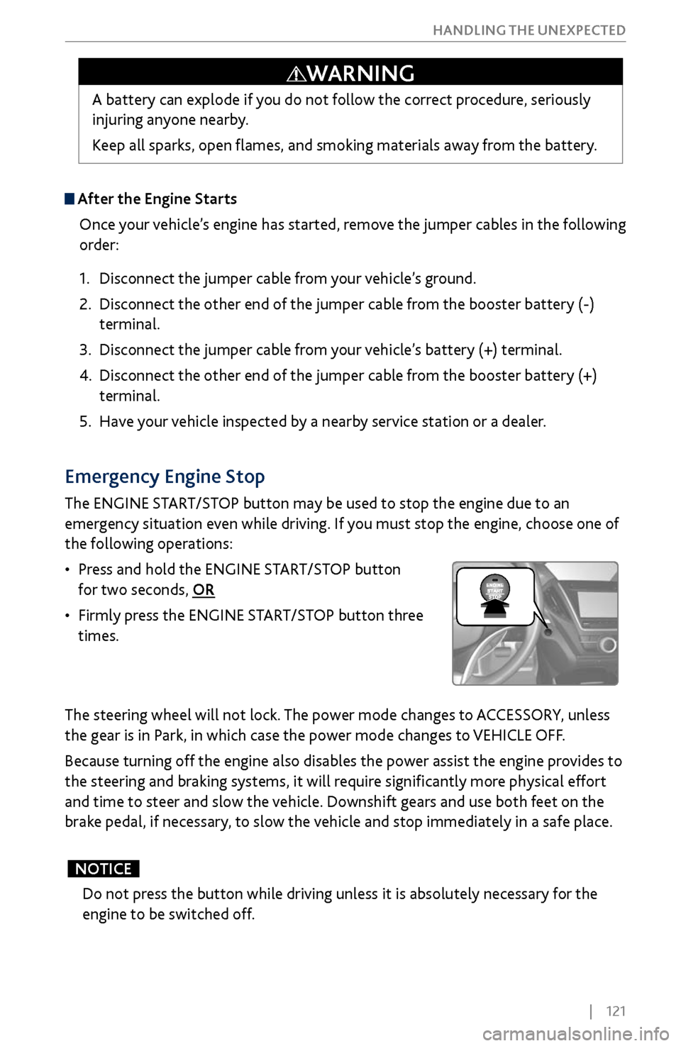
The ENGINE START/STOP button may be used to stop the engine due to an
emergency situation even while driving. If you must stop the engine, choose one of
the following operations:
•
Press and hold the ENGINE
START/STOP button
for two seconds, OR
•
Firmly press
the ENGINE START/STOP button three
times.
The steering wheel will not lock. The power mode changes to ACCESSORY, unless
the gear is in Park, in which case the power mode changes to VEHICLE OFF.
Because turning off the engine also disables the power assist the engine provides to
the steering and braking systems, it will require significantly more physical effort
and time to steer and slow the vehicle. Downshift gears and use both feet on the
brake pedal, if necessary, to slow the vehicle and stop immediately in a safe place.
Do not press the button while driving unless it is absolutely necessary for the
engine to be switched off.
NOTICE
Page 134 of 170
| 127
HANDLING THE UNEXPECTED
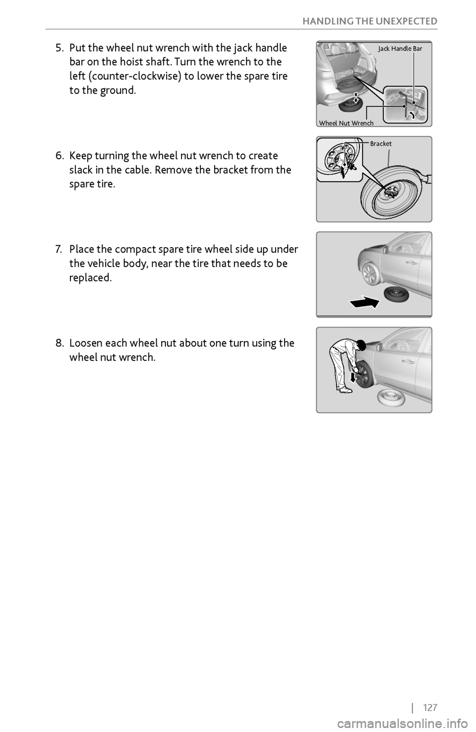
5. Put the wheel nut wrench with the jack handle
bar on the hoist
shaft. Turn the wrench to the
left (counter-clockwise) to lower the spare tire
to the ground.
6.
Keep turning the wheel
nut wrench to create
slack in the cable. Remove the bracket from the
spare tire.
7.
Place the compact
spare tire wheel side up under
the vehicle body, near the tire that needs to be
replaced.
8.
Loosen each wheel nut about one
turn using the
wheel nut wrench.
Handl e
Cargo Floor Box
Tool Case
Cove r
Wheel Nut Wrench
Jack Handle Bar
Bracket
Handl e
Cargo Floor Box
Tool Case
Cove r
Wheel Nut Wrench
Jack Handle Bar
Bracket
Handl e
Cargo Floor Box
Tool Case
Cove r
Wheel Nut Wrench
Jack Handle Bar
Bracket
Handl e
Cargo Floor Box
Tool Case
Cove r
Wheel Nut Wrench
Jack Handle Bar
Bracket
Page 135 of 170
128 |
HANDLING THE UNEXPECTED
Setting Up the Jack
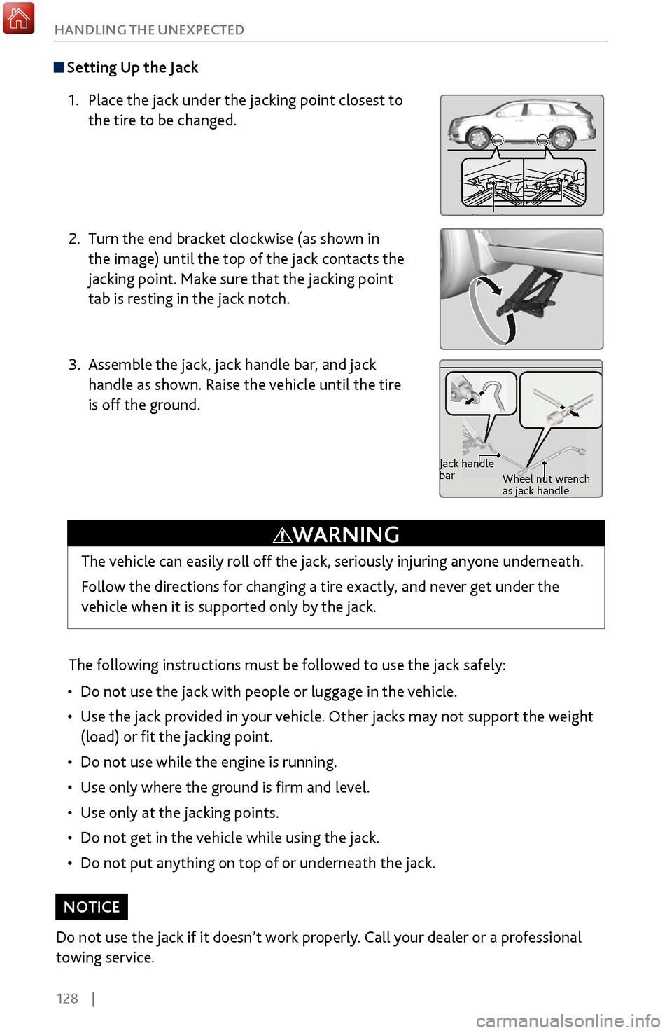
1.
Place the jack under the jacking point closest
to
the tire to be changed.
2.
Turn the end bracket clockwise (as shown in
the
image) until the top of the jack contacts the
jacking point. Make sure that the jacking point
tab is resting in the jack notch.
3.
Assemble the jack, jack handle bar, and jack
handle as shown. Raise
the vehicle until the tire
is off the ground.
The following instructions must be followed to use the jack safely:
•
Do not use the jack with people
or luggage in the vehicle.
•
Use the jack pro
vided in your vehicle. Other jacks may not support the weight
(load) or fit the jacking point.
•
Do not use while the engine is running.
•
Use only
where the ground is firm and level.
•
Use only at
the jacking points.
•
Do not get in the v
ehicle while using the jack.
•
Do not put
anything on top of or underneath the jack.
Jacking PointsJacking PointsJacking Points
Jack handle
barWheel nut wrench
as jack handle
The vehicle can easily roll off the jack, seriously injuring anyone underneath.
Follow the directions for changing a tire exactly, and never get under the
vehicle when it is supported only by the jack.
WARNING
Do not use the jack if it doesn’t work properly. Call your dealer or a professional
towing service.
NOTICE
Page 136 of 170
| 129
HANDLING THE UNEXPECTED
Replacing the Flat Tire
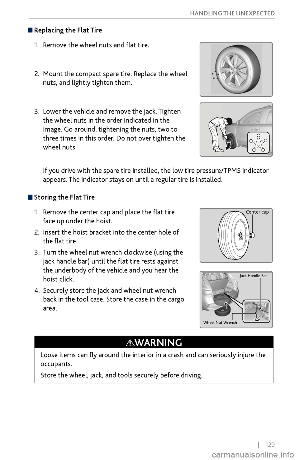
1.
Remov
e the wheel nuts and flat tire.
2.
Mount the compact spar
e tire. Replace the wheel
nuts, and lightly tighten them.
3.
Lower the v
ehicle and remove the jack. Tighten
the wheel nuts in the order indicated in the
image. Go around, tightening the nuts, two to
three times in this order. Do not over tighten the
wheel nuts.
If you drive with the spare tire installed, the low tire pressure/TPMS indicator
appears. The indicator stays on until a regular tire is installed.
Storing the Flat Tire
1.
Remov
e the center cap and place the flat tire
face up under the hoist.
2.
Insert the hoist bracket into
the center hole of
the flat tire.
3.
Turn the wheel nut
wrench clockwise (using the
jack handle bar) until the flat tire rests against
the underbody of the vehicle and you hear the
hoist click.
4.
Securely stor
e the jack and wheel nut wrench
back in the tool case. Store the case in the cargo
area.
Wheel Nut Wrench
Ja ck Handle Bar
Loose items can fly around the interior in a crash and can seriously injure the
occupants.
Store the wheel, jack, and tools securely before driving.
WARNING
Center cap
Page 138 of 170
| 131
HANDLING THE UNEXPECTED
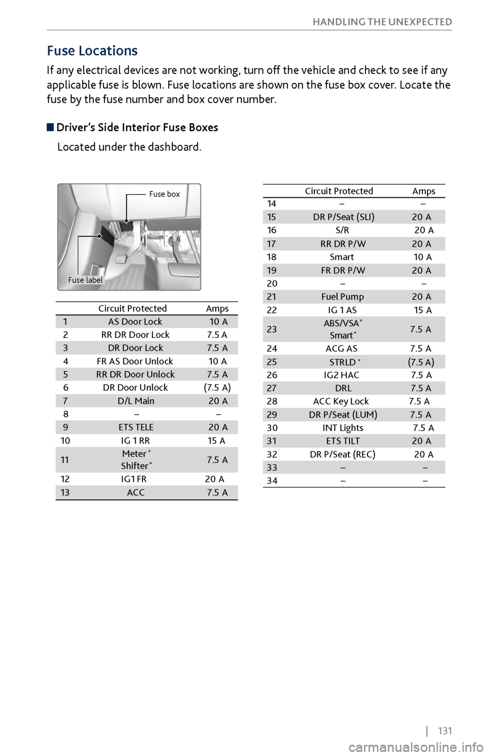
Fuse Locations
If any electrical devices are not working, turn off the vehicle and check to see if any
applicable fuse is blown. Fuse locations are shown on the fuse box cover. Locate the
fuse by the fuse number and box cover number.
Driver’s Side Interior Fuse Boxes
Located under the dashboard.
Fuse box
Fuse label
Circuit ProtectedAmps1AS Door Lock10 A2RR DR Door Lock7.5 A3DR Door Lock7.5A4FR AS Door Unlock10 A5RR DR Door Unlock7.5A6DR Door Unloc k(7.5A )7D/L Main20A8��9ETS TELE20A
10 IG 1 RR 15A
11Meter*
Shifter*7.5A
12 IG1 FR 20A
13ACC7.5A
14 ��
15 DR P/Seat (SLI) 20A
16 S/R2 0A
17RR DR P/W 20A
18 Smart1 0A
19 FR DR P/W 20A
20 ��
21 Fuel Pump 20A
22 IG 1 AS 15A
23 ABS/VS
A
*
Smar t*7.5 A
24 ACG AS 7.5 A
25
26 IG2 HAC 7.5 A
27 DRL 7.5 A
28 ACC Key Lock 7.5A
29 DR P/Seat (LUM) 7.5 A
30 INT Lights 7.5A
31 ETS TILT 20A
32 DR P/Seat (REC) 20A
33 � �
34 � �
Circuit Protected
Amps
STRLD (7.5 A)
*
Circuit Protected Amps
1 AS Door Lock 10A
2 RR DR Door Lock 7.5 A
3 DR Door Lock 7.5A
4 FR AS Door Unlock 10A
5 RR DR Door Unlock 7.5A
6 DR Door Unloc k(7.5A )
7 D/L Main 20A
8 � �
9 ETS TELE 20A
10 IG 1 RR 15A
11 Meter
*
Shifter*7.
5A
12 IG1 FR 20A
13 ACC 7.5A
14��15DR P/Seat (SLI)20 A
16 S/R20A
17RR DR P/W20A
18 Smart10A19FR DR P/W20A
20��21Fuel Pump20 A
22 IG 1 AS 15A
23ABS/VS A*
Smar t*7.5 A
24 ACG AS 7.5 A
2526 IG2 HAC 7.5 A27DRL7.5 A
28 ACC Key Lock 7.5A
29DR P/Seat (LUM)7.5 A
30 INT Lights 7.5A
31ETS TILT20A
32 DR P/Seat (REC) 20A
33��34��
Circuit ProtectedAmps
STRLD (7.5 A)*
Page 146 of 170
| 139
MAINTENANCE
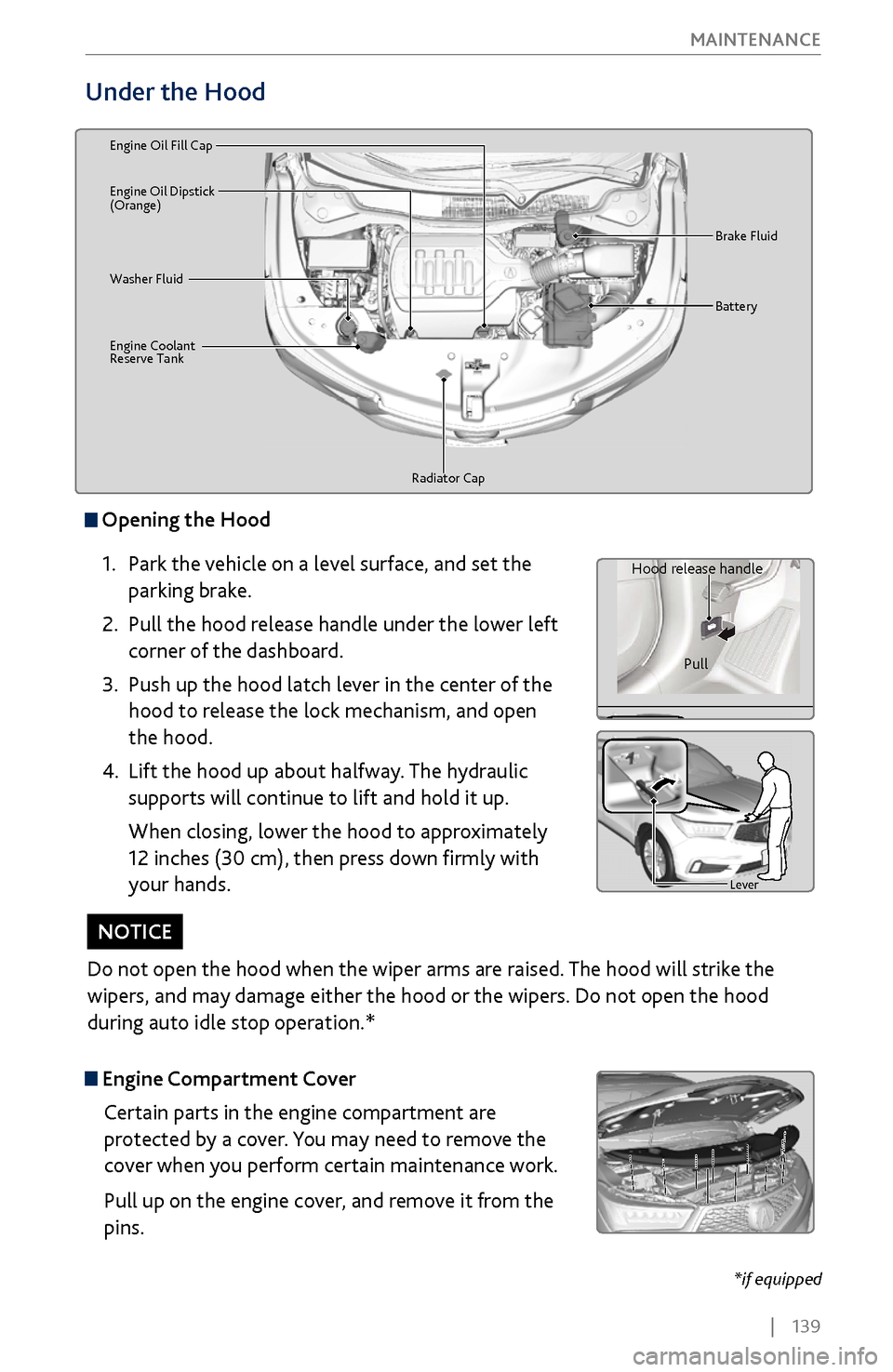
Under the Hood
Brake Fluid
Washer Fluid
Radiator Cap
Engine Coolant
Reserve Tan
k Batter
y
Engine Oil Dipstick
(Orange) Engine Oil Fill Ca
p
Opening the Hood
1.
Park the
vehicle on a level surface, and set the
parking brake.
2.
Pull the hood release handle under
the lower left
corner of the dashboard.
3.
Push up the hood latch lever in
the center of the
hood to release the lock mechanism, and open
the hood.
4.
Lift the hood up about halfway.
The hydraulic
supports will continue to lift and hold it up.
When closing, lower the hood to approximately
12 inches (30 cm), then press down firmly with
your hands.
Lever
Hood release handle
Pull
Lever
Engine Compartment CoverCertain parts in the engine compartment are
protected by a cover. You may need to remove the
cover when you perform certain maintenance work.
Pull up on the engine cover, and remove it from the
pins.
Do not open the hood when the wiper arms are raised. The hood will strike the
wipers, and may damage either the hood or the wipers. Do not open the hood
during auto idle stop operation.*
NOTICE
*if equipped