ACURA NSX 1991 Service Repair Manual
Manufacturer: ACURA, Model Year: 1991, Model line: NSX, Model: ACURA NSX 1991Pages: 1640, PDF Size: 60.48 MB
Page 1151 of 1640
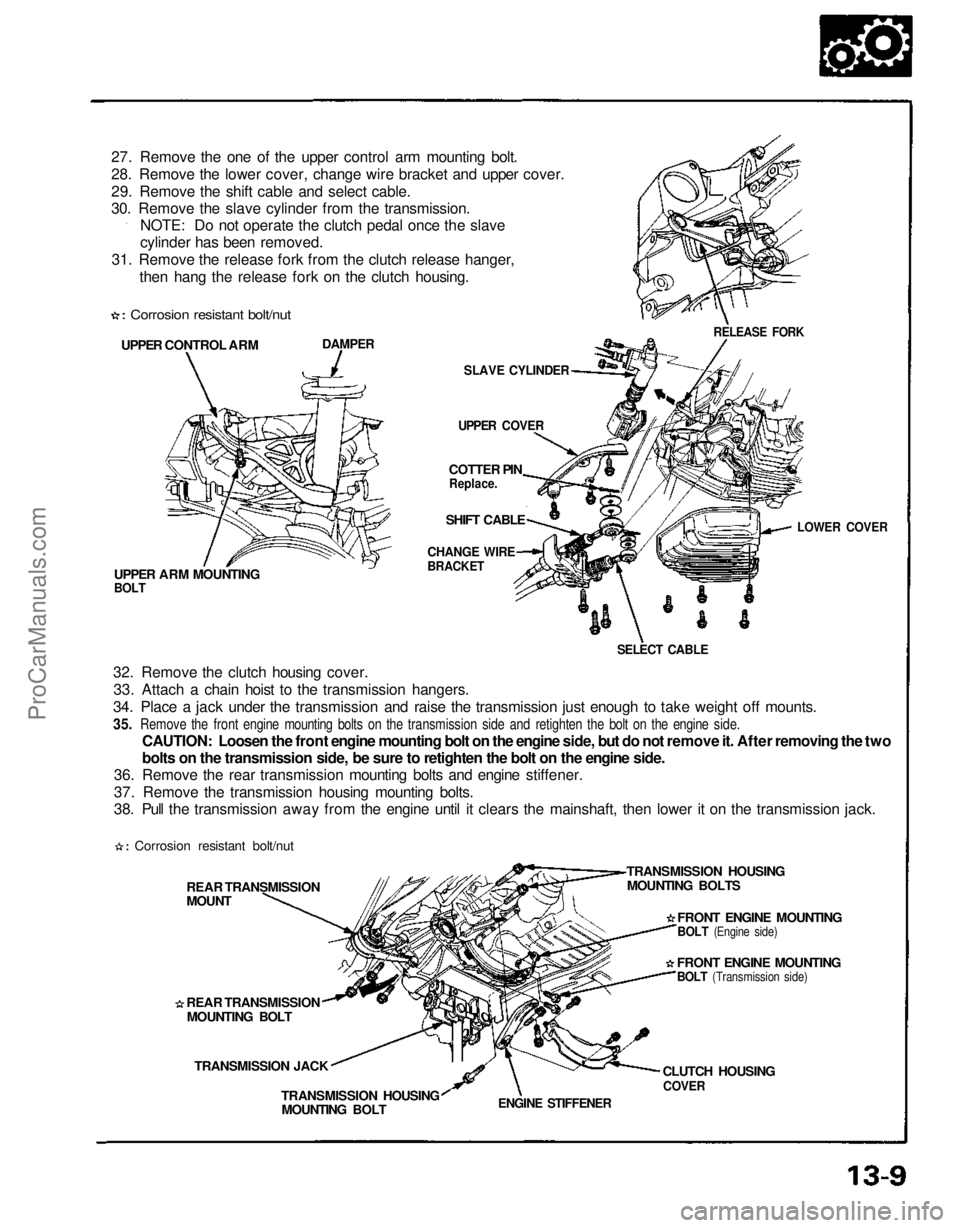
27. Remove the one of the upper control arm mounting bolt.
28. Remove the lower cover, change wire bracket and upper cover.
29. Remove the shift cable and select cable.
30. Remove the slave cylinder from the transmission.
NOTE: Do not operate the clutch pedal once the slave
cylinder has been removed.
31. Remove the release fork from the clutch release hanger, then hang the release fork on the clutch housing.
UPPER CONTROL ARM
DAMPER
SLAVE CYLINDER
UPPER COVER
UPPER ARM MOUNTING
BOLT
32. Remove the clutch housing cover. 33. Attach a chain hoist to the transmission hangers.
34. Place a jack under the transmission and raise the transmission just enough to take weight off mounts.
35. Remove the front engine mounting bolts on the transmission side and retighten the bolt on the engine side.
CAUTION: Loosen the front engine mounting bolt on the engine side, but do not remove it. After removing the two
bolts on the transmission side, be sure to retighten the bolt on the engine side.
36. Remove the rear transmission mounting bolts and engine stiffener.
37. Remove the transmission housing mounting bolts.
38. Pull the transmission away from the engine until it clears the mainshaft, then lower it on the transmission jack.
REAR TRANSMISSION
MOUNT
REAR TRANSMISSIONMOUNTING BOLT
TRANSMISSION JACK TRANSMISSION HOUSINGMOUNTING BOLT
ENGINE STIFFENER
CLUTCH HOUSING
COVER
TRANSMISSION HOUSING
MOUNTING BOLTS
FRONT ENGINE MOUNTING
BOLT
(Engine side)
FRONT ENGINE MOUNTING
BOLT
(Transmission side)
RELEASE FORK
COTTER PIN
Replace.
SHIFT CABLE
CHANGE WIRE
BRACKET
SELECT CABLE
LOWER COVER
Corrosion resistant bolt/nut
Corrosion resistant bolt/nutProCarManuals.com
Page 1152 of 1640
Illustrated Index
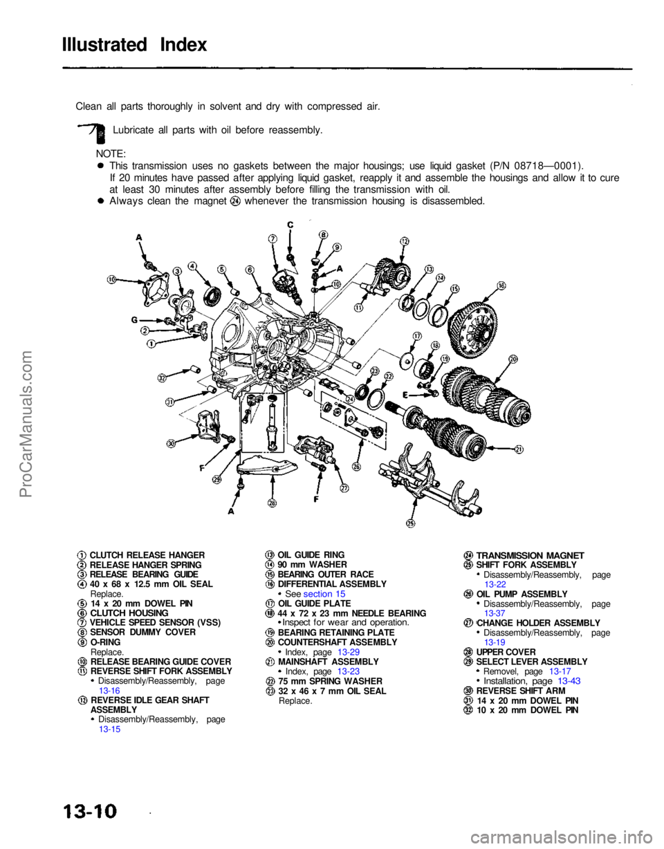
Clean all parts thoroughly in solvent and dry with compressed air. Lubricate all parts with oil before reassembly.
NOTE: This transmission uses no gaskets between the major housings; use liquid gasket (P/N 08718—0001).If 20 minutes have passed after applying liquid gasket, reapply it and assemble the housings and allow it to cure
at least 30 minutes after assembly before filling the transmission with oil. Always clean the magnet whenever the transmission housing is disassembled.
Disassembly/Reassembly, page13-22
Disassembly/Reassembly, page 13-37
Disassembly/Reassembly, page 13-19
Removel, page 13-17
Installation, page 13-43
REVERSE SHIFT ARM 14 x 20 mm DOWEL PIN
10 x 20 mm DOWEL PIN
CLUTCH RELEASE HANGER
RELEASE HANGER SPRING
RELEASE BEARING GUIDE
40 x 68 x 12.5 mm OIL SEAL
Replace. 14 x 20 mm DOWEL PIN
CLUTCH HOUSING
VEHICLE SPEED SENSOR (VSS)
SENSOR DUMMY COVER
O-RING
Replace.
RELEASE BEARING GUIDE COVER
REVERSE SHIFT FORK ASSEMBLY Disassembly/Reassembly, page
13-16
REVERSE IDLE GEAR SHAFT
ASSEMBLY Disassembly/Reassembly, page
13-15 OIL GUIDE RING
90 mm WASHER
BEARING OUTER RACE
DIFFERENTIAL ASSEMBLY
See section 15
OIL GUIDE PLATE
44 x 72 x 23 mm NEEDLE BEARING
Inspect for wear and operation.
BEARING RETAINING PLATE
COUNTERSHAFT ASSEMBLY Index, page 13-29
MAINSHAFT ASSEMBLY Index, page 13-23
75 mm SPRING WASHER
32 x 46 x 7 mm OIL SEAL
Replace.
TRANSMISSION MAGNET
SHIFT FORK ASSEMBLY
OIL PUMP ASSEMBLYCHANGE HOLDER ASSEMBLY
UPPER COVER
SELECT LEVER ASSEMBLYProCarManuals.com
Page 1153 of 1640
BEARING OUTER RACE
75 mm THRUST SHIM
Selection.
CLAMP
BACK-UP LIGHT SWITCH
25 N.m (2·5 kg-m. 18 Ib-ft)
CLAMP
TRANSMISSION HANGER A
TRANSMISSION HANGER B
STAY
WASHER
Replace.
OIL FILLER PLUG
45 N .
m (4·5 kg-m. 33 Ib-ft)
42 x 63 x 12.5 mm OIL SEAL
Replace.
WASHER
Replace.
DRAIN PLUG
40 N·m (4.0 kg-m. 29 Ib-ft) 36 mm SEALING BOLT
35 N .
m (3.5 kg-m, 25 Ib-ft)
STRAINER COVER
O-RING
Replace.
STRAINER SET SPRING
OIL PUMP STRAINER 14 mm SEALING BOLT
33 N .
m (3.3 kg-m, 24 Ib-ft)
SPRING (L. 25 mm)
STEEL BALL (3/8 in)
16 mm SEALING BOLT
42 N .
m (4.2 kg-m. 30 Ib-ft)
SPRING (L. 25.1 mm)
16 mm SEALING BOLTS
42 N .
m (4.2 kg-m. 30 Ib-ft)
SPRING (L. 30 mm)
STEEL BALL (5/16 in)
SHIFT LEVER ASSEMBLY Removal, page 13-17
Installation, page 13-43
NEUTRAL POSITION SWITCH
25 N .
m (2.5 kg-m, 18 Ib-ft)
TRANSMISSION HOUSING
OIL GUIDE PLATE
82 mm THRUST SHIM
Selection, page 13-41ProCarManuals.com
Page 1154 of 1640
SEALING
BOLT
STEEL
BALLS (5/16 in)
Transmission Housing
Removal
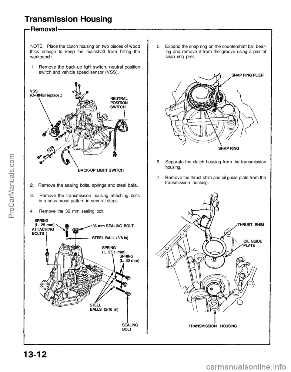
NOTE: Place the clutch housing on two pieces of wood
thick enough to keep the mainshaft from hitting the
workbench.
1. Remove the back-up light switch, neutral position
switch and vehicle speed sensor (VSS).
NEUTRAL
POSITION
SWITCH
VSS
(O-RING Replace .)
BACK-UP LIGHT SWITCH36 mm SEALING BOLT
SPRING
(L. 25 mm)
ATTACHING BOLTS
2. Remove the sealing bolts, springs and steel balls.
3. Remove the transmission housing attaching bolts in a criss-cross pattern in several steps.
4. Remove the 36 mm sealing bolt.
STEEL BALL (3/8 in)
SPRING
(L.
25.1
mm)
SPRING
(L. 30 mm)
TRANSMISSION HOUSINGTHRUST SHIM
OIL GUIDE
PLATE
6. Separate the clutch housing from the transmission
housing. SNAP RINGSNAP RING PLIER
5. Expand the snap ring on the countershaft ball bear-
ing and remove it from the groove using a pair of
snap ring plier.
7. Remove the thrust shim and oil guide plate from the transmission housing.ProCarManuals.com
Page 1155 of 1640
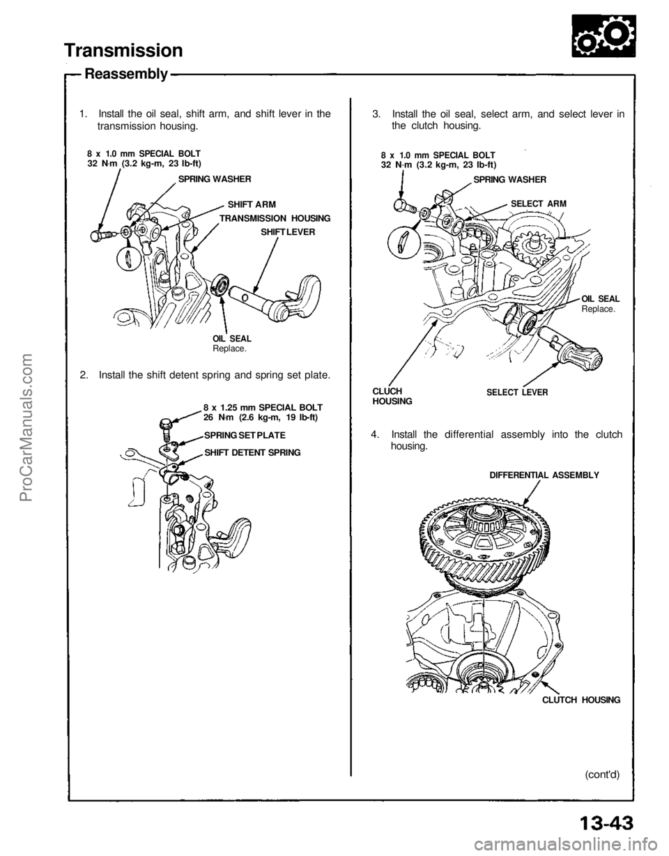
Transmission
Reassembly
1. Install the oil seal, shift arm, and shift lever in the transmission housing.
8 x 1.0 mm SPECIAL BOLT
32 N .
m (3.2 kg-m, 23 Ib-ft)
SPRING WASHER
SHIFT ARM
TRANSMISSION HOUSING SHIFT LEVER
OIL SEAL
Replace.
2. Install the shift detent spring and spring set plate.
8 x 1.25 mm SPECIAL BOLT
26 N.
m (2.6 kg-m, 19 Ib-ft)
SPRING SET PLATE SHIFT DETENT SPRING 3. Install the oil seal, select arm, and select lever in
the clutch housing.
8 x 1.0 mm SPECIAL BOLT
32 N·m (3.2 kg-m, 23 Ib-ft) SPRING WASHER
SELECT ARM
OIL SEAL
Replace.
SELECT LEVER
CLUCH
HOUSING
4. Install the differential assembly into the clutch housing.
DIFFERENTIAL ASSEMBLY
CLUTCH HOUSING
(cont'd)ProCarManuals.com
Page 1156 of 1640
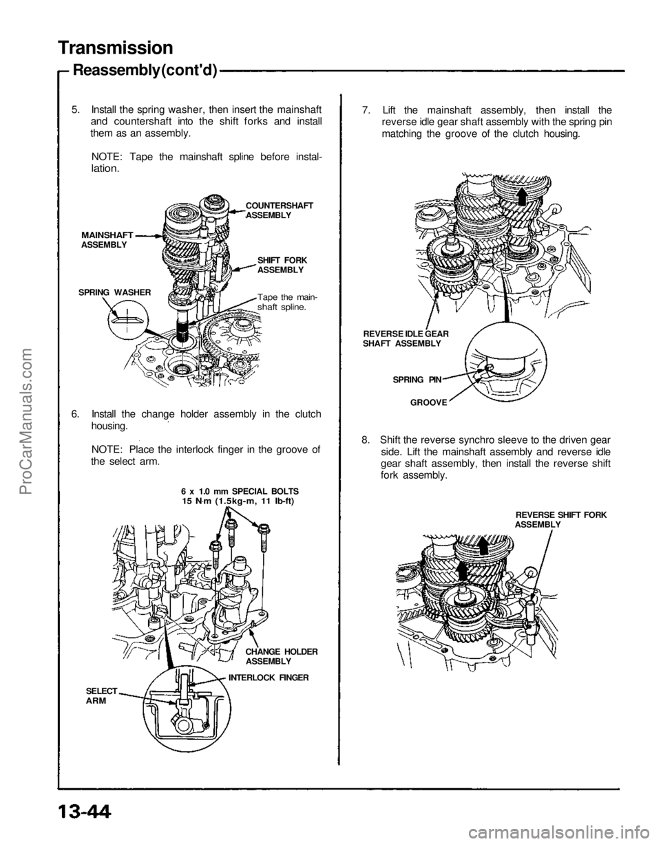
Transmission
Reassembly (cont'd)
5. Install the spring washer, then insert the mainshaft and countershaft into the shift forks and install
them as an assembly.
NOTE: Tape the mainshaft spline before instal-
lation.
COUNTERSHAFT
ASSEMBLY
SPRING WASHER
6. Install the change holder assembly in the clutch housing.
NOTE: Place the interlock finger in the groove of
the select arm.
SELECT
ARM
CHANGE HOLDER
ASSEMBLY
INTERLOCK FINGER 8. Shift the reverse synchro sleeve to the driven gear
side. Lift the mainshaft assembly and reverse idle
gear shaft assembly, then install the reverse shift
fork assembly.
REVERSE SHIFT FORK
ASSEMBLY
7. Lift the mainshaft assembly, then install the
reverse idle gear shaft assembly with the spring pin
matching the groove of the clutch housing.
REVERSE IDLE GEAR
SHAFT ASSEMBLY
SPRING PIN
GROOVE
MAINSHAFT
ASSEMBLY
6 x 1.0 mm SPECIAL BOLTS
15 N .
m (1.5kg-m, 11 Ib-ft)
SHIFT FORK
ASSEMBLY
Tape the main-
shaft spline.ProCarManuals.com
Page 1157 of 1640
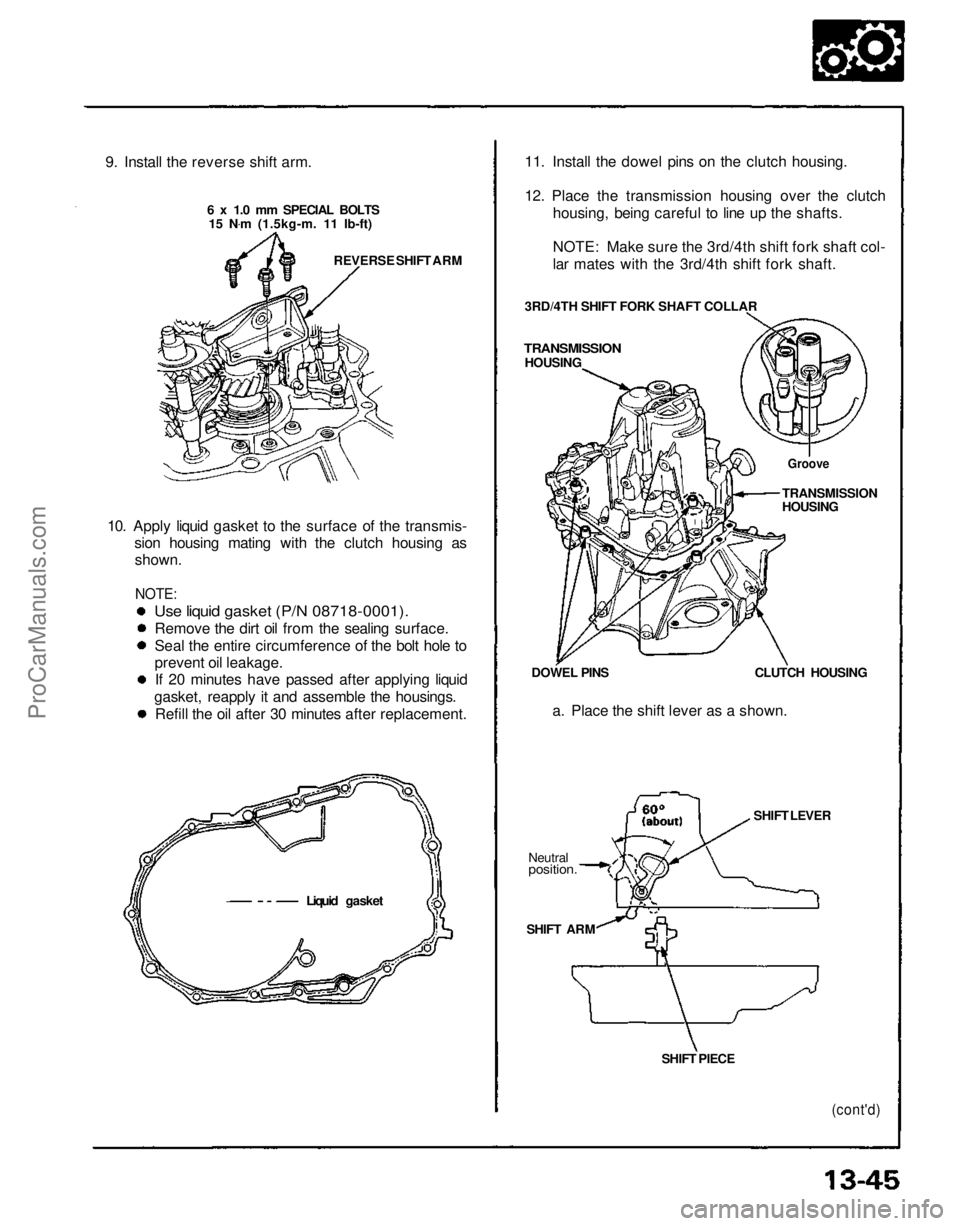
9. Install the reverse shift arm.
6 x 1.0 mm SPECIAL BOLTS15 N .
m (1.5kg-m. 11 Ib-ft)
REVERSE SHIFT ARM
10. Apply liquid gasket to the surface of the transmis- sion housing mating with the clutch housing asshown.
NOTE:
Use liquid gasket (P/N 08718-0001).
Remove the dirt oil from the sealing surface.
Seal the entire circumference of the bolt hole to
prevent oil leakage.If 20 minutes have passed after applying liquid
gasket, reapply it and assemble the housings. Refill the oil after 30 minutes after replacement.
Liquid gasket SHIFT PIECE
SHIFT ARM
Neutral
position.
SHIFT LEVERCLUTCH HOUSING
a. Place the shift lever as a shown.
DOWEL PINS
TRANSMISSION
HOUSING 3RD/4TH SHIFT FORK SHAFT COLLAR 11. Install the dowel pins on the clutch housing.
12. Place the transmission housing over the clutch
housing, being careful to line up the shafts.
NOTE: Make sure the 3rd/4th shift fork shaft col-
lar mates with the 3rd/4th shift fork shaft.
Groove
TRANSMISSION
HOUSING
(cont'd)ProCarManuals.com
Page 1158 of 1640
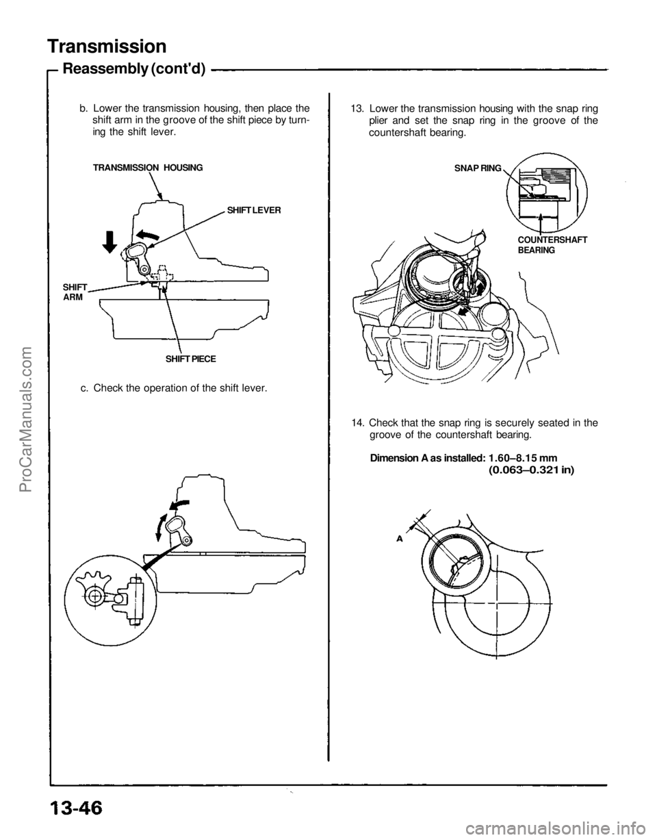
Transmission
Reassembly (cont'd)
b. Lower the transmission housing, then place theshift arm in the groove of the shift piece by turn-
ing the shift lever.
TRANSMISSION HOUSING
SHIFT
ARM
SHIFT PIECESHIFT LEVER
c. Check the operation of the shift lever. 13. Lower the transmission housing with the snap ring
plier and set the snap ring in the groove of the
countershaft bearing.
SNAP RING
COUNTERSHAFT
BEARING
14. Check that the snap ring is securely seated in the groove of the countershaft bearing.
Dimension A as installed: 1.60–8.15 mm
(0.063–0.321 in)ProCarManuals.com
Page 1159 of 1640
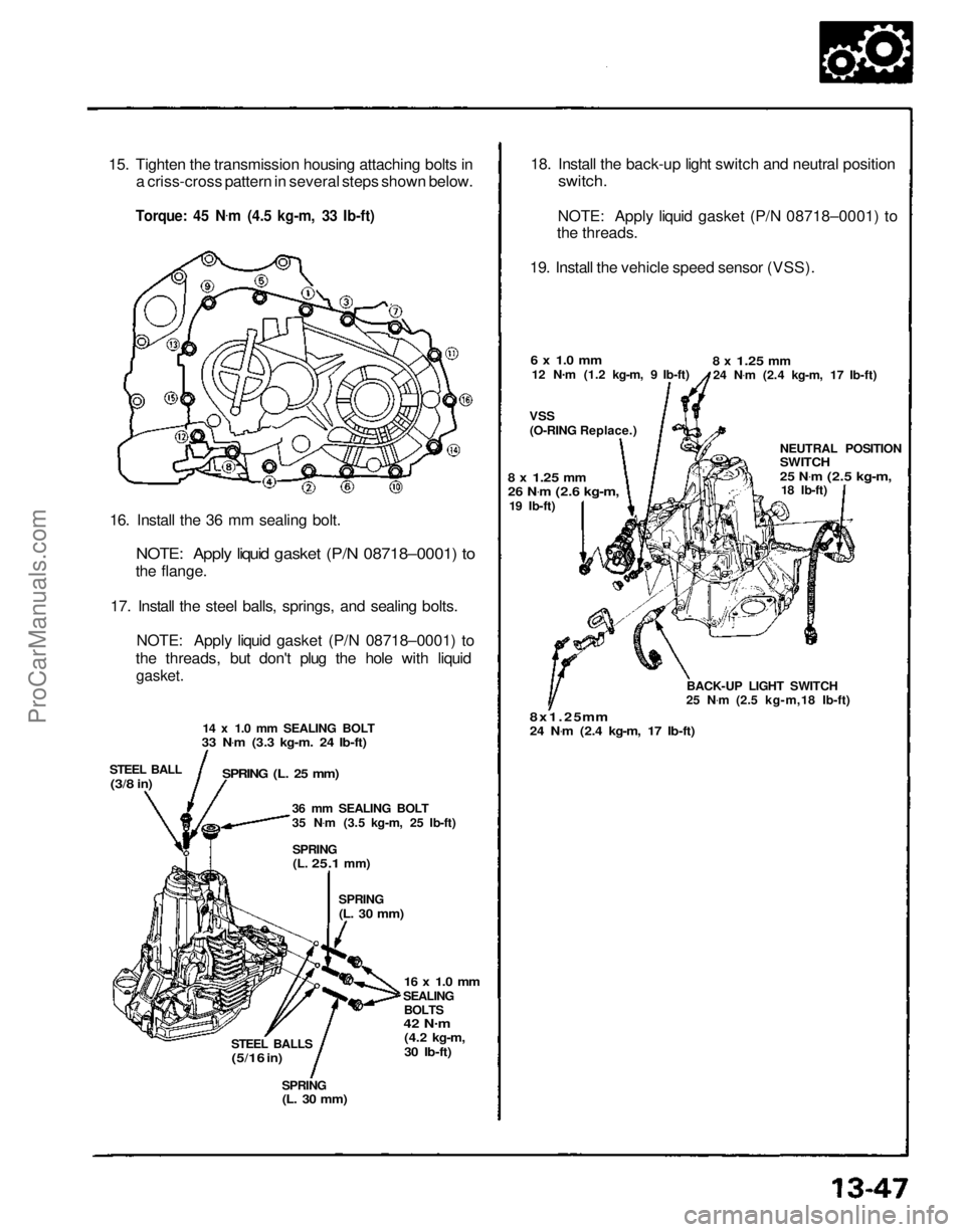
15. Tighten the transmission housing attaching bolts in
a criss-cross pattern in several steps shown below.
Torque: 45 N .
m (4.5 kg-m, 33 Ib-ft)
16. Install the 36 mm sealing bolt.
NOTE: Apply liquid gasket (P/N 08718–0001) to
the flange.
17. Install the steel balls, springs, and sealing bolts. NOTE: Apply liquid gasket (P/N 08718–0001) to
the threads, but don't plug the hole with liquid
gasket.
14 x 1.0 mm SEALING BOLT
33 N .
m (3.3 kg-m. 24 Ib-ft)
STEEL BALL
(3/8
in)
SPRING (L. 25 mm)
36 mm SEALING BOLT
35 N.
m (3.5 kg-m, 25 Ib-ft)
SPRING
(L.
25.1
mm)
SPRING
(L. 30 mm)
16 x 1.0 mm
SEALING BOLTS
42 N .
m
(4.2 kg-m,
30 Ib-ft)
STEEL BALLS
(5/16
in)
SPRING
(L. 30 mm)
18. Install the back-up light switch and neutral position
switch.
NOTE: Apply liquid gasket (P/N 08718–0001) to
the threads.
19. Install the vehicle speed sensor (VSS).
6 x 1.0 mm
12 N .
m (1.2 kg-m, 9 Ib-ft)
VSS
(O-RING Replace.)
8 x
1.25
mm
24 N .
m (2.4 kg-m, 17 Ib-ft)
NEUTRAL POSITION
SWITCH
25 N.
m
(2.5 kg-m,
18 Ib-ft)
BACK-UP LIGHT SWITCH
25 N .
m (2.5 kg-m,18 Ib-ft)
8x1.25 mm
24 N .
m (2.4 kg-m, 17 Ib-ft)
8 x
1.25
mm
26 N
.
m
(2.6 kg-m,
19 Ib-ft)ProCarManuals.com
Page 1160 of 1640
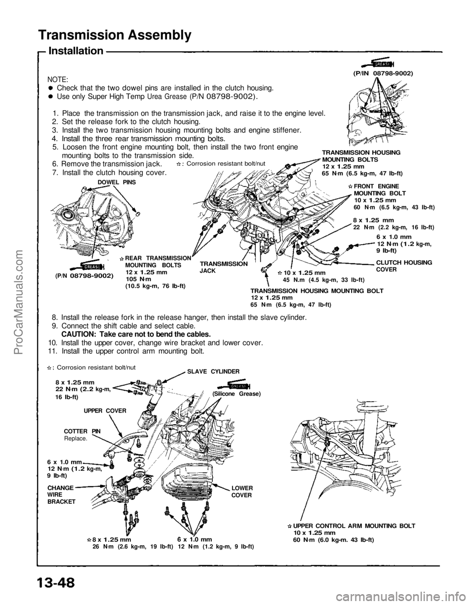
Transmission Assembly
Installation
NOTE:
Check that the two dowel pins are installed in the clutch housing.
Use
only Super High Temp
Urea
Grease
(P/N
08798-9002).
1. Place the transmission on the transmission jack, and raise it to the engine level.
2. Set the release fork to the clutch housing.
3. Install the two transmission housing mounting bolts and engine stiffener.
4. Install the three rear transmission mounting bolts.
5. Loosen the front engine mounting bolt, then install the two front engine
mounting bolts to the transmission side.
6. Remove the transmission jack.
7. Install the clutch housing cover.
Corrosion resistant bolt/nut
DOWEL PINS
(P/N
08798-9002)
REAR TRANSMISSION
MOUNTING BOLTS
12 x
1.25
mm
105 N .
m
(10.5 kg-m, 76 Ib-ft)
(P/lN 08798-9002)
TRANSMISSION HOUSING
MOUNTING BOLTS
12 x
1.25
mm
65 N .
m (6.5 kg-m, 47 Ib-ft)
FRONT ENGINE
MOUNTING BOLT
10 x
1.25
mm
60 N .
m (6.5 kg-m, 43 Ib-ft)
8 x
1.25
mm
22 N .
m (2.2 kg-m, 16 Ib-ft)
6 x 1.0 mm
12 N .
m
(1.2
kg-m,
9 Ib-ft)
CLUTCH HOUSING
COVER
10 x
1.25
mm
45 N.m (4.5 kg-m, 33 Ib-ft)
TRANSMISSION HOUSING MOUNTING BOLT
12 x
1.25
mm
65 N .
m (6.5 kg-m, 47 Ib-ft)
TRANSMISSION
JACK
8. Install the release fork in the release hanger, then install the slave cylinder.
9. Connect the shift cable and select cable. CAUTION: Take care not to bend the cables.
10. Install the upper cover, change wire bracket and lower cover.
11. Install the upper control arm mounting bolt.
Corrosion resistant bolt/nut
8 x
1.25
mm
22 N .
m
(2.2
kg-m,
16 Ib-ft)
UPPER COVER
COTTER PIN Replace.
6 x 1.0 mm
12 N .
m
(1.2
kg-m,
9 Ib-ft)
CHANGE
WIRE
BRACKET
8 x
1.25
mm
26 N .
m (2.6 kg-m, 19 Ib-ft)
6 x 1.0 mm
12 N .
m (1.2 kg-m, 9 Ib-ft) LOWER
COVER
UPPER CONTROL ARM MOUNTING BOLT
10 x
1.25
mm
60 N .
m (6.0 kg-m. 43 Ib-ft)
(Silicone Grease)
SLAVE CYLINDERProCarManuals.com