roof ACURA NSX 1991 Service Repair Manual
[x] Cancel search | Manufacturer: ACURA, Model Year: 1991, Model line: NSX, Model: ACURA NSX 1991Pages: 1640, PDF Size: 60.48 MB
Page 99 of 1640
Cylinder Heads
Removal
Engine removal is not required for this procedure. Make sure jacks and safety stands are
placed properly and hoist brackets ere attached to cor- rect positions on the engine.
CAUTION: Use a fender cover (special tool) to avoid damaging
painted surfaces. Unplug the wiring connectors carefully while holding
the connector portion to avoid damage.
To avoid damaging the cylinder heads, wait until the
engine coolant temperature drops below 100°F
(38°C) before loosening the retaining bolts. Do not open the engine cover when the roof panel is
stored (NSX-T open top).
NOTE:
Unspecified items are common.
Mark all wiring and hoses to avoid misconnection.
Also, be sure that they do not contact other wiring or
hoses or interfere with other parts.
Inspect the timing belt before removing the cylinder
head.
Turn the crankshaft pulley SO that the No. 1 piston is at top dead center (see page 6-19 ('91-'93) or ('94-'96)).
1. Disconnect the negative terminal from the battery.
2. Remove the expansion tank cap. Use care when removing the expan-
sion tank cap to avoid scalding by engine coolant
or steam.
3. Raise the car, then remove the right rear wheel/tire.
4. Drain the engine coolant (see page 10-5 ). 5. Remove the engine under guard, then remove the
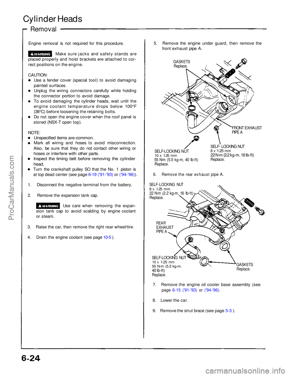
front exhaust pipe A.
GASKETS
Replace.
FRONT EXHAUST
PIPE A
SELF-LOCKING NUT
10 x
1.25
mm
55 N·m (5.5 kg-m, 40 Ib-ft)
Replace.
SELF- LOCKING NUT
8 x
1.25
mm
22 N·m (2.2 kg-m. 16 Ib-ft)
Replace.
6. Remove the rear exhaust pipe A.
SELF- LOCKING NUT
8 x
1.25
mm
22 N·m (2.2 kg-m, 16 Ib-ft)
Replace.
REAR
EXHAUST
PIPE A
SELF-LOCKING NUT
10 x
1.25
mm
55 N·m (5.5 kg-m.
40 Ib-ft)
Replace.
GASKETS
Replace.
7. Remove the engine oil cooler base assembly (see
page 6-15 ('91-'93) or ('94-'96).
8. Lower the car.
9. Remove the strut brace (see page 5-3 ).ProCarManuals.com
Page 561 of 1640
Construction
Features
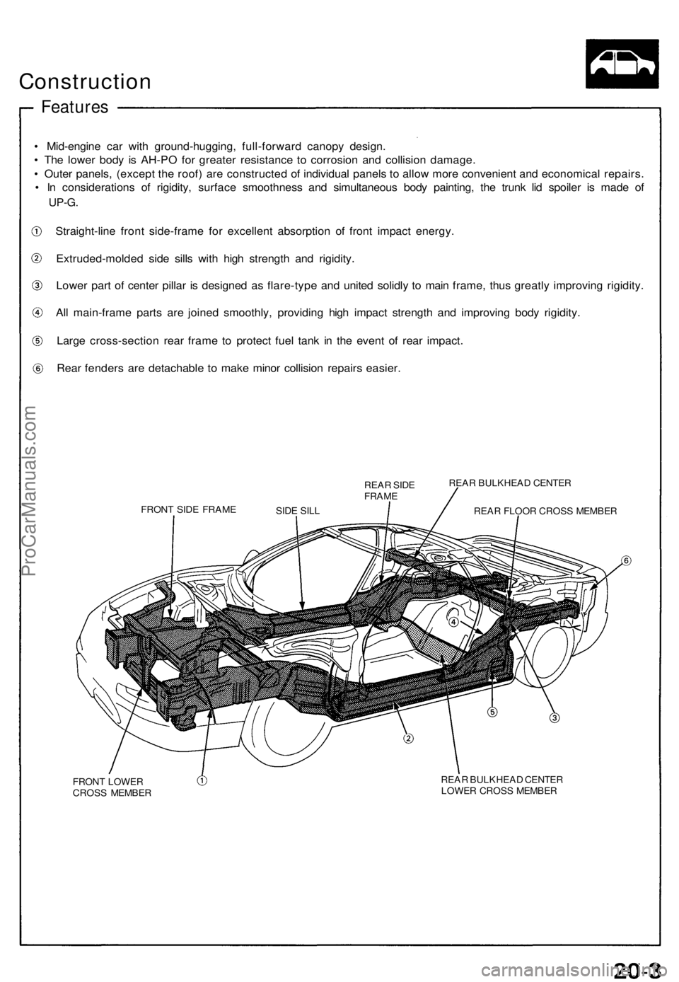
• Mid-engin e ca r wit h ground-hugging , full-forwar d canop y design .
• Th e lowe r bod y i s AH-P O fo r greate r resistanc e t o corrosio n an d collisio n damage .
• Oute r panels , (excep t th e roof ) ar e constructe d o f individua l panel s t o allo w mor e convenien t an d economica l repairs .
• I n consideration s o f rigidity , surfac e smoothnes s an d simultaneou s bod y painting , th e trun k li d spoile r i s mad e o f
UP-G .
Straight-lin e fron t side-fram e fo r excellen t absorptio n o f fron t impac t energy .
Extruded-molde d sid e sill s wit h hig h strengt h an d rigidity .
Lowe r par t o f cente r pilla r i s designe d a s flare-typ e an d unite d solidl y t o mai n frame , thu s greatl y improvin g rigidity .
Al l main-fram e part s ar e joine d smoothly , providin g hig h impac t strengt h an d improvin g bod y rigidity .
Larg e cross-sectio n rea r fram e t o protec t fue l tan k i n th e even t o f rea r impact .
Rea r fender s ar e detachabl e t o mak e mino r collisio n repair s easier .
REAR SID EFRAM E
FRONT SID E FRAM E REA
R BULKHEA D CENTE R
REA R FLOO R CROS S MEMBE R
FRON T LOWE R
CROS S MEMBE R REA
R BULKHEA D CENTE R
LOWE R CROS S MEMBE R
SID
E SIL L
ProCarManuals.com
Page 562 of 1640
Construction
Composition
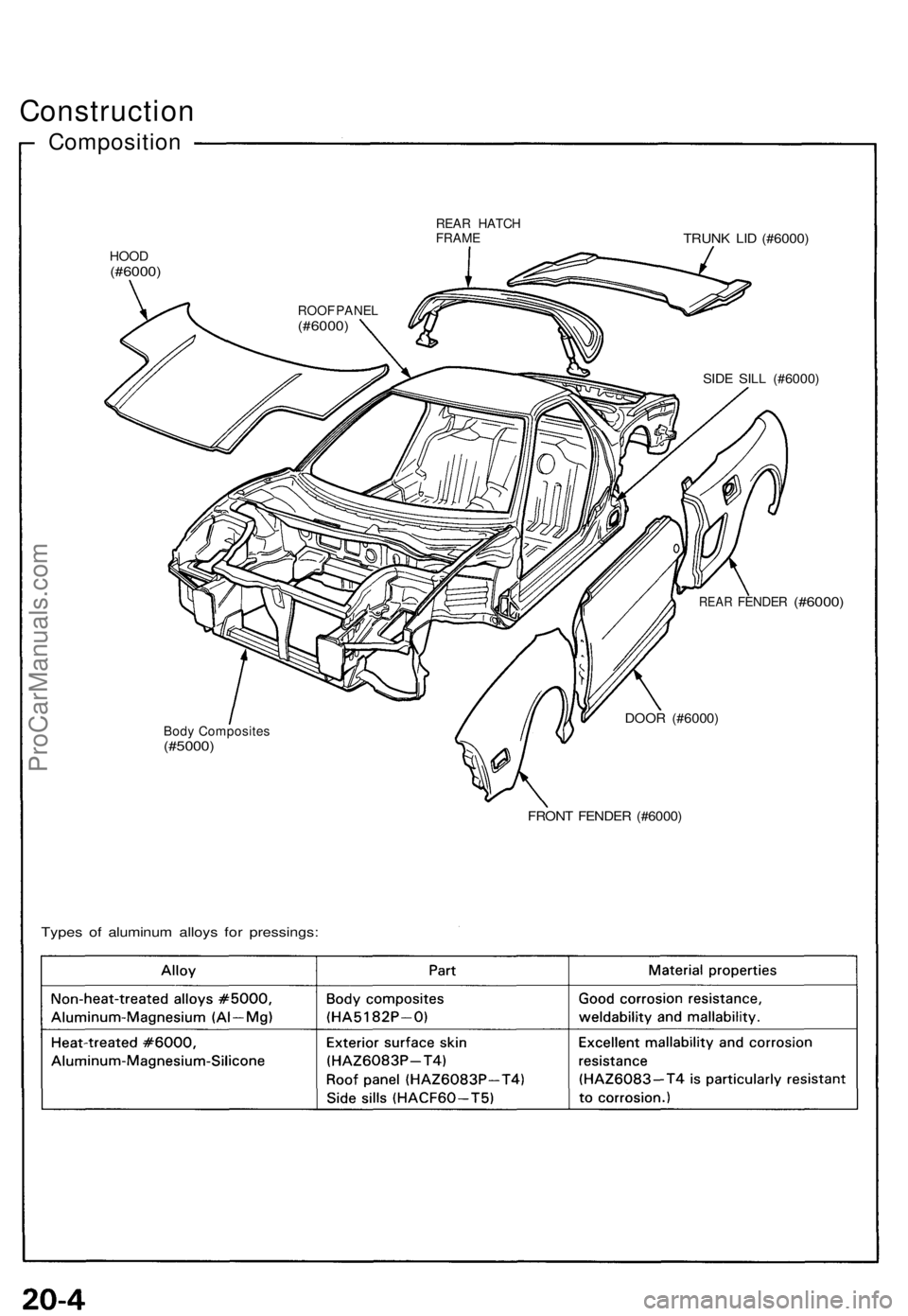
REAR HATC HFRAMETRUNK LI D (#6000 )
HOOD(#6000 )
SIDE SIL L (#6000 )
REAR FENDE R (#6000)
Body Composite s(#5000)
DOOR (#6000 )
FRONT FENDE R (#6000 )
Types o f aluminu m alloys for pressings :
ROOF PANE L(#6000 )
ProCarManuals.com
Page 634 of 1640
Roof Rai l Trim , Fron t an d Rea r
Replacemen t
CAUTION:
• Wea r glove s t o remov e an d instal l th e trim .
• Whe n pryin g wit h a fla t ti p screwdriver , wra p it wit h
protectiv e tap e t o preven t damage .
NOTE:
• Tak e car e no t t o scratc h th e trim .
• Remov e th e roof .
Fron t roo f rai l trim :
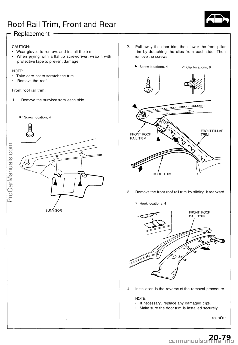
1 . Remov e th e sunviso r fro m eac h side .
Scre w location , 4
SUNVISO R
2. Pul l awa y th e doo r trim , the n lowe r th e fron t pilla r
tri m b y detachin g th e clip s fro m eac h side . The n
remov e th e screws .
Screw locations , 4
Clip locations , 8
DOO R TRI M
3. Remov e th e fron t roo f rai l tri m b y slidin g i t rearward .
Hook locations , 4
FRONT ROO F
RAI L TRI M
4. Installatio n i s th e revers e o f th e remova l procedure .
NOTE:
• I f necessary , replac e an y damage d clips .
• Mak e sur e th e doo r tri m is installe d securely .
FRONT ROO F
RAI L TRI M FRON
T PILLA RTRIM
ProCarManuals.com
Page 635 of 1640
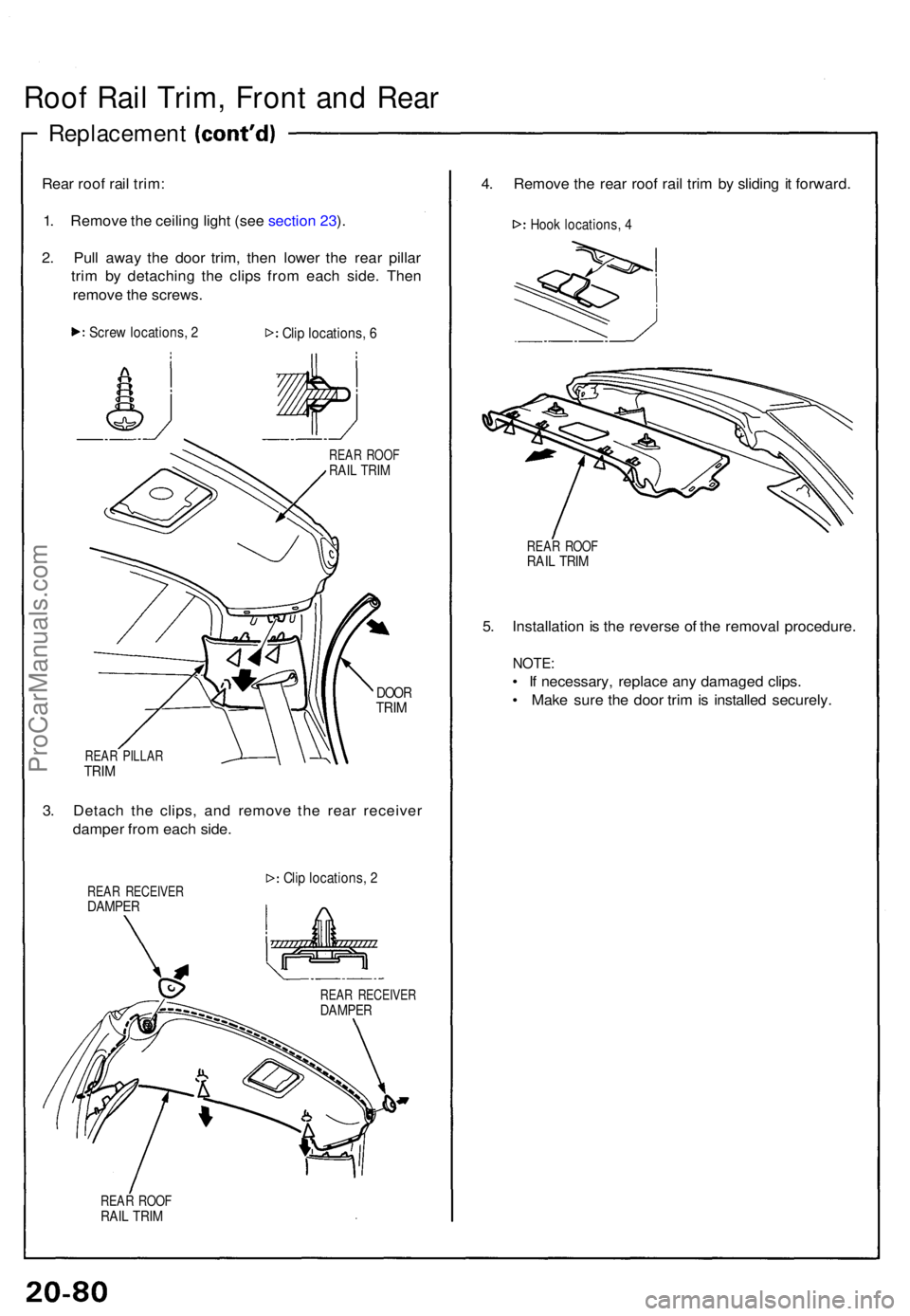
Roof Rai l Trim , Fron t an d Rea r
Replacemen t
Rear roo f rai l trim :
1 . Remov e th e ceilin g ligh t (se e sectio n 23 ).
2 . Pul l awa y th e doo r trim , the n lowe r th e rea r pilla r
tri m b y detachin g th e clip s fro m eac h side . The n
remov e th e screws .
Screw locations , 2Cli p locations , 6
REA R ROO FRAIL TRI M
DOO RTRIM
REA R PILLA RTRIM
3. Detac h th e clips , an d remov e th e rea r receive r
dampe r fro m eac h side .
REAR RECEIVE RDAMPER
Clip locations , 2
REA R ROO FRAIL TRI M
4. Remov e th e rea r roo f rai l tri m b y slidin g it forward .
Hook locations , 4
REA R ROO FRAIL TRI M
5. Installatio n is th e revers e o f th e remova l procedure .
NOTE:
• I f necessary , replac e an y damage d clips .
• Mak e sur e th e doo r tri m is installe d securely .
REAR RECEIVE RDAMPER
ProCarManuals.com
Page 636 of 1640
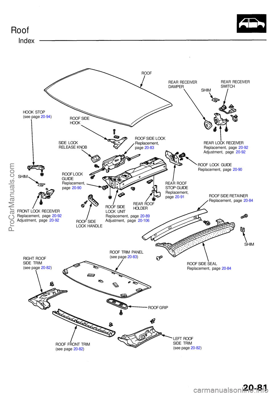
Roof
Inde x
ROO F
HOOK STO P
(se e pag e 20-94 )
SHIM
REA R RECEIVE RDAMPERSHIM
REA R RECEIVE RSWITCH
SID E LOC K
RELEAS E KNO B ROO
F SID E LOC K
Replacement ,page 20-8 3
ROO F LOC K
GUID EReplacement ,
pag e 20-9 0
FRON T LOC K RECEIVE R
Replacement , pag e 20-9 2
Adjustment , pag e 20-9 2
ROOF SID E
LOC K HANDL EREAR ROO FSTOP GUID EReplacement ,
pag e 20-9 1 REA
R LOC K RECEIVE R
Replacement , pag e 20-9 2
Adjustment , pag e 20-9 2
ROO F LOC K GUID E
Replacement , pag e 20-9 0
ROO F SID E RETAINE R
Replacement , pag e 20-8 4
RIGH T ROO F
SID E TRI M
(se e pag e 20-82 ) ROO
F TRI M PANE L
(se e pag e 20-83 )
SHIM
ROO F SID E SEA L
Replacement , pag e 20-8 4
ROO F FRON T TRI M
(se e pag e 20-82 ) LEF
T ROO F
SID E TRI M
(se e pag e 20-82 )
ROO
F GRI P
ROO
F SID E
HOO K
ROOF
SIDELOC K UNI T
Replacement , pag e 20-8 9
Adjustment , pag e 20-10 6
REAR ROO FHOLDE R
ProCarManuals.com
Page 637 of 1640
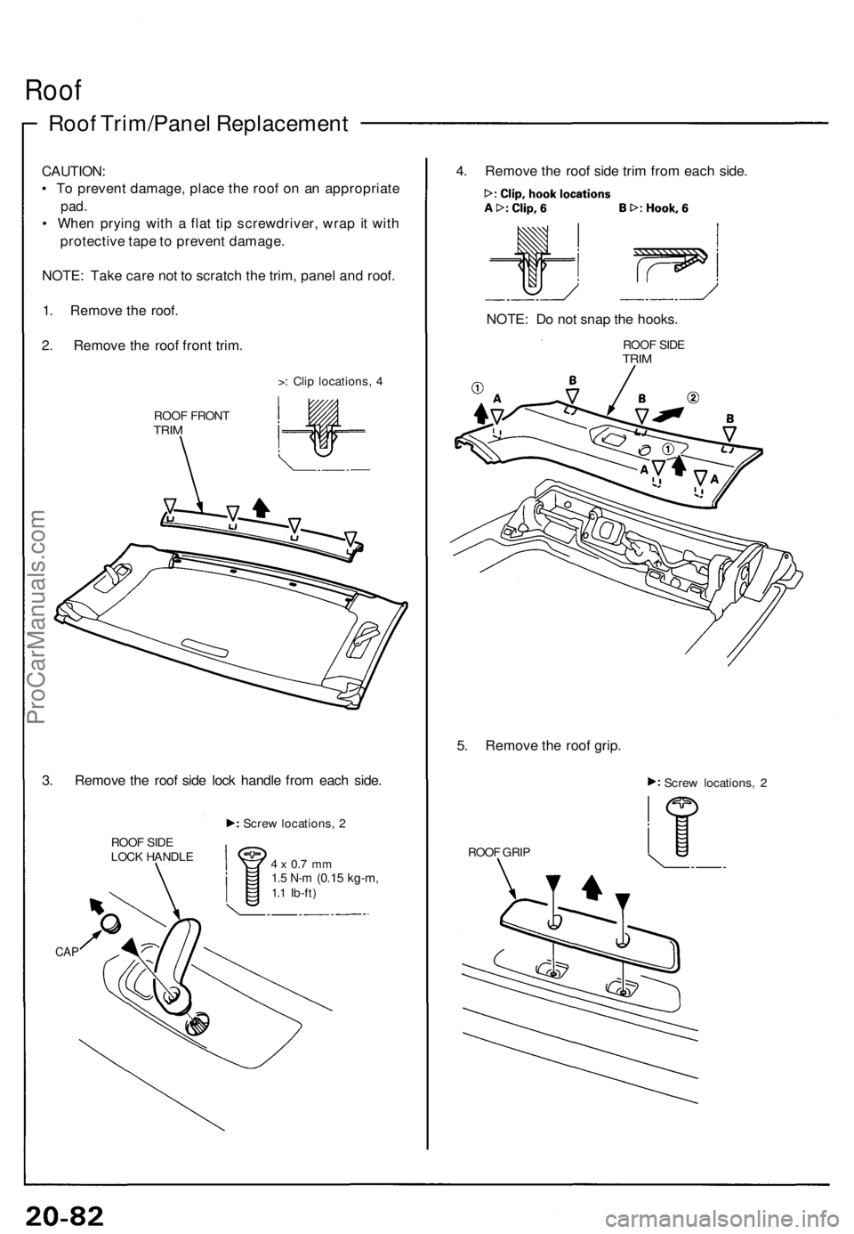
Roof
Roof Trim/Pane l Replacemen t
CAUTION:
• T o preven t damage , plac e th e roo f o n a n appropriat e
pad.
• Whe n pryin g wit h a fla t ti p screwdriver , wra p it wit h
protectiv e tap e to preven t damage .
NOTE : Tak e car e no t t o scratc h th e trim , pane l an d roof .
1 . Remov e th e roof .
2 . Remov e th e roo f fron t trim .
>: Cli p locations , 4
ROO F FRON T
TRIM
3. Remov e th e roo f sid e loc k handl e fro m eac h side .
ROO F SID E
LOC K HANDL E Scre
w locations , 2
4 x 0. 7 m m1.5 N- m (0.1 5 kg-m ,1.1 Ib-ft )
CAP
4. Remov e th e roo f sid e tri m fro m eac h side .
NOTE : D o no t sna p th e hooks .
ROOF SID ETRIM
5. Remov e th e roo f grip .
Scre w locations , 2
ROO F GRI P
ProCarManuals.com
Page 638 of 1640
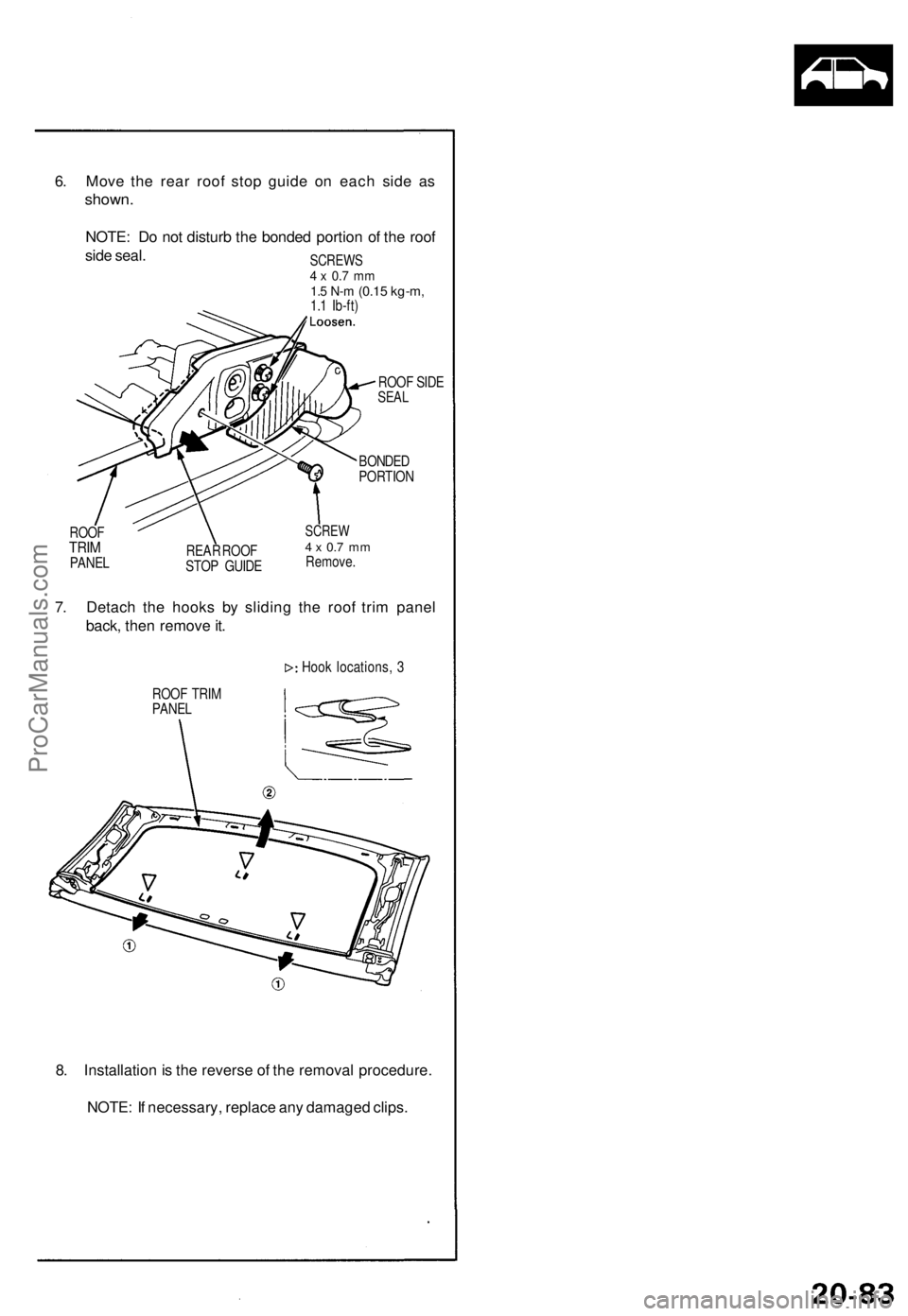
6. Move the rear roof stop guide on each side as
shown.
NOTE: Do not disturb the bonded portion of the roof
side seal.
SCREWS
4 x 0.7 mm
1.5 N-m
(0.15 kg-m,
1.1 Ib-ft)
ROOF SIDE
SEAL
BONDED
PORTION
ROOF
TRIM
PANEL
REAR ROOF
STOP GUIDE
SCREW
4 x 0.7 mm
Remove.
7. Detach the hooks by sliding the roof trim panel
back, then remove it.
Hook locations, 3
ROOF TRIM
PANEL
8. Installation is the reverse of the removal procedure.
NOTE: If necessary, replace any damaged clips.ProCarManuals.com
Page 639 of 1640
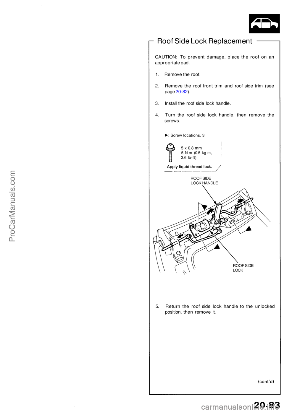
Roof Sid e Loc k Replacemen t
CAUTION: T o preven t damage , plac e th e roo f o n a n
appropriat e pad .
1 . Remov e th e roof .
2 . Remov e th e roo f fron t tri m an d roo f sid e tri m (se e
pag e 20-82 ).
3 . Instal l th e roo f sid e loc k handle .
4 . Tur n th e roo f sid e loc k handle , the n remov e th e
screws .
Screw locations , 3
5 x 0. 8 m m5 N- m (0. 5 kg-m ,3.6 Ib-ft )
ROOF SID E
LOC K
5. Retur n th e roo f sid e loc k handl e t o th e unlocke d
position , the n remov e it .
ROO F SID E
LOC K HANDL E
ProCarManuals.com
Page 640 of 1640
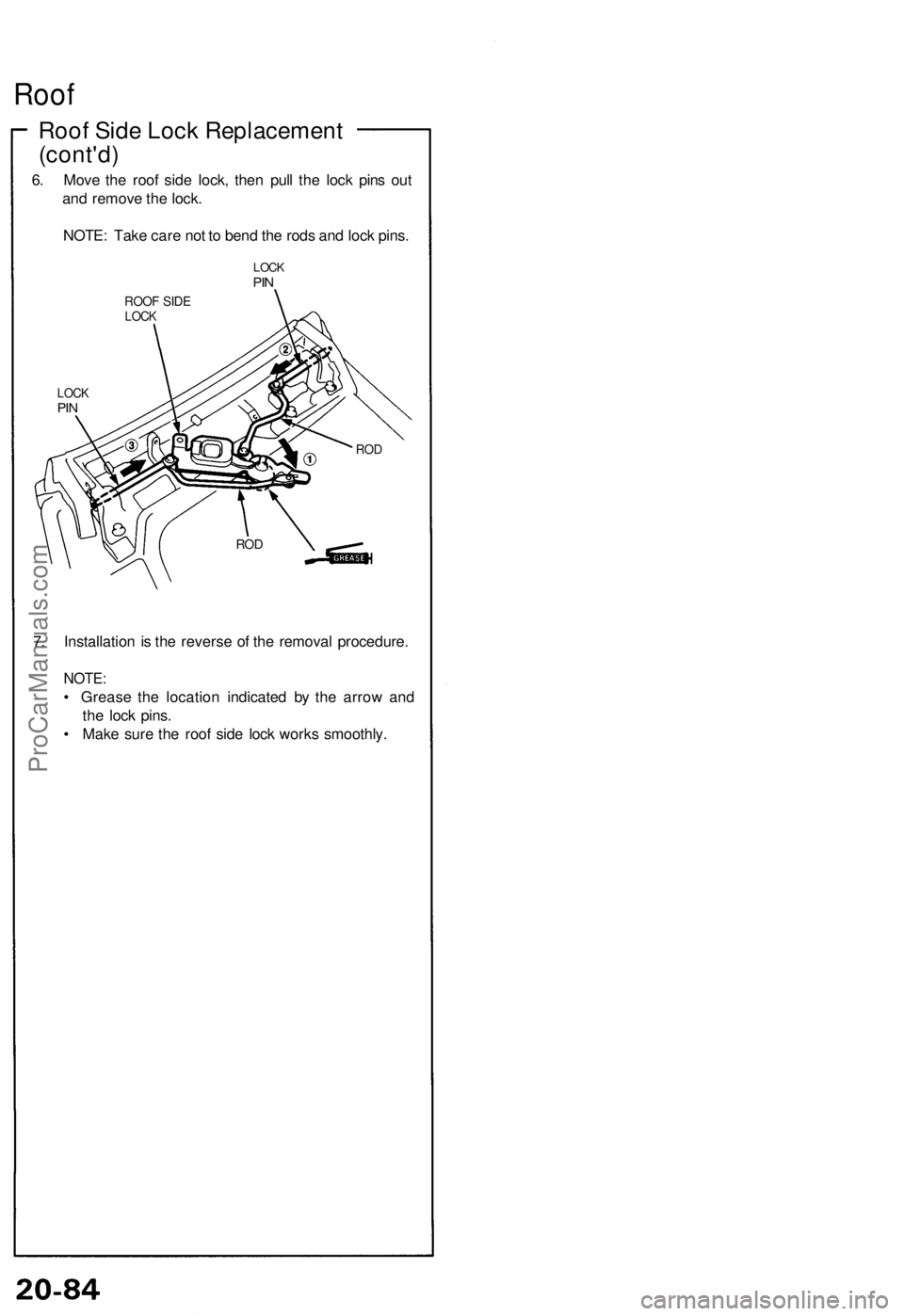
Roof
Roof Side Lock Replacement
(cont'd)
6. Move the roof side lock, then pull the lock pins out
and remove the lock.
NOTE: Take care not to bend the rods and lock pins.
LOCK
PIN
ROOF SIDE
LOCK
LOCK
PIN
7. Installation is the reverse of the removal procedure.
NOTE:
• Grease the location indicated by the arrow and
the lock pins.
• Make sure the roof side lock works smoothly.
ROD
RODProCarManuals.com