wheel torque ACURA NSX 1991 Service Repair Manual
[x] Cancel search | Manufacturer: ACURA, Model Year: 1991, Model line: NSX, Model: ACURA NSX 1991Pages: 1640, PDF Size: 60.48 MB
Page 45 of 1640
Service Precaution s
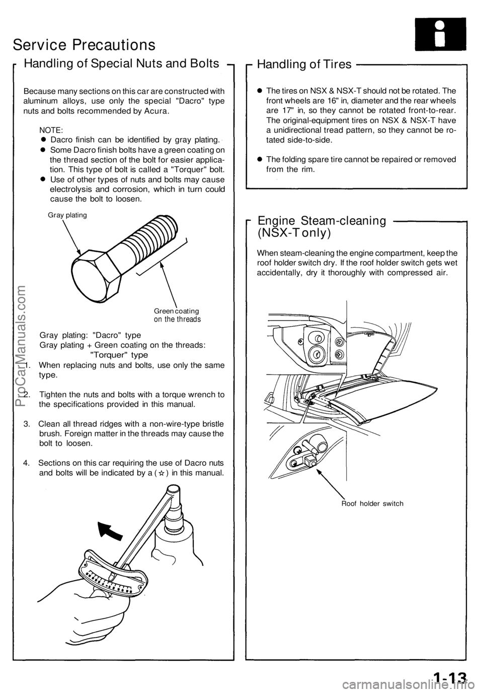
Handling o f Specia l Nut s an d Bolt s
Becaus e man y section s o n thi s ca r ar e constructe d wit h
aluminu m alloys , us e onl y th e specia l "Dacro " typ e
nut s an d bolt s recommende d b y Acura .
NOTE:
Dacro finis h ca n b e identifie d b y gra y plating .
Som e Dacr o finis h bolt s hav e a gree n coatin g o n
th e threa d sectio n of the bol t fo r easie r applica -
tion . Thi s typ e of bol t i s calle d a "Torquer " bolt .
Us e o f othe r type s of nut s an d bolt s ma y caus e
electrolysi s an d corrosion , whic h in tur n coul d
caus e th e bol t t o loosen .
Gray platin g
Green coatin g
on th e thread s
Gray plating : "Dacro " typ e
Gra y platin g + Gree n coatin g o n th e threads :
"Torquer " typ e
1. Whe n replacin g nut s an d bolts , us e onl y th e sam e
type.
2. Tighte n th e nut s an d bolt s with a torqu e wrenc h t o
th e specification s provide d i n thi s manual .
3 . Clea n al l threa d ridge s wit h a non-wire-typ e bristl e
brush . Foreig n matte r i n th e thread s ma y caus e th e
bol t t o loosen .
4 . Section s o n thi s ca r requirin g th e us e o f Dacr o nut s
and bolt s wil l b e indicate d b y a ( ) in thi s manual .
Handling o f Tire s
The tire s o n NS X & NSX- T shoul d no t b e rotated . Th e
fron t wheel s ar e 16 " in , diamete r an d th e rea r wheel s
ar e 17 " in , s o the y canno t b e rotate d front-to-rear .
Th e original-equipmen t tire s o n NS X & NSX- T hav e
a unidirectiona l trea d pattern , s o the y canno t b e ro -
tate d side-to-side .
Th e foldin g spar e tir e canno t b e repaire d o r remove d
fro m th e rim .
Engin e Steam-cleanin g
(NSX-T only )
When steam-cleanin g th e engin e compartment , kee p th e
roo f holde r switc h dry . I f th e roo f holde r switc h get s we t
accidentally , dr y i t thoroughl y wit h compresse d air .
Roo f holde r switc h
ProCarManuals.com
Page 373 of 1640
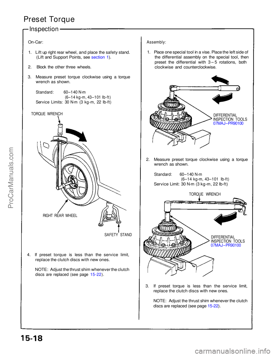
Preset Torque
Inspection
On-Car:
1. Lift up right rear wheel,
and place the safety stand.
(Lift and Support Points, see section 1).
2. Block the other three wheels.
3. Measure preset torque clockwise using a torque wrench as shown.
Standard:
60–140 N·m
(6–14 kg-m, 43–101 Ib-ft)
Service Limits: 30 N·m (3 kg-m, 22 Ib-ft)
TORQUE WRENCH
RIGHT REAR WHEEL SAFETY STAND
4. If preset torque is less than the service limit, replace the clutch discs with new ones.
NOTE: Adjust the thrust shim whenever the clutch
discs are replaced (see page 15-22).
Assembly:
1. Place one special tool in a vise. Place the left side of the differential assembly on the special tool, then
preset the differential with 3 – 5 rotations, both
clockwise and counterclockwise.
DIFFERENTIAL
INSPECTION TOOLS
07MAJ– PR90100
2. Measure preset torque clockwise using a torque wrench as shown.
Standard: 60–140 N·m
(6–14 kg-m, 43–101 Ib-ft)
Service Limit: 30 N·m (3 kg-m, 22 Ib-ft)
TORQUE WRENCH
DIFFERENTIAL
INSPECTION TOOLS
07MAJ – PR90100
3. If preset torque is less than the service limit, replace the clutch discs with new ones.
NOTE: Adjust the thrust shim whenever the clutch
discs are replaced (see page 15-22).
ProCarManuals.com
Page 408 of 1640
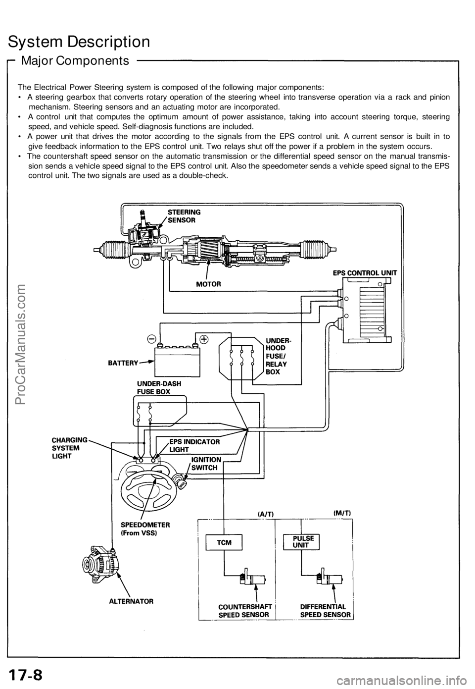
System Description
Major Components
The Electrical Power Steering system is composed of the following major components:
• A steering gearbox that converts rotary operation of the steering wheel into transverse operation via a rack and pinion
mechanism. Steering sensors and an actuating motor are incorporated.
• A control unit that computes the optimum amount of power assistance, taking into account steering torque, steering
speed, and vehicle speed. Self-diagnosis functions are included.
• A power unit that drives the motor according to the signals from the EPS control unit. A current sensor is built in to
give feedback information to the EPS control unit. Two relays shut off the power if a problem in the system occurs.
• The countershaft speed sensor on the automatic transmission or the differential speed sensor on the manual transmis-
sion sends a vehicle speed signal to the EPS control unit. Also the speedometer sends a vehicle speed signal to the EPS
control unit. The two signals are used as a double-check.ProCarManuals.com
Page 409 of 1640
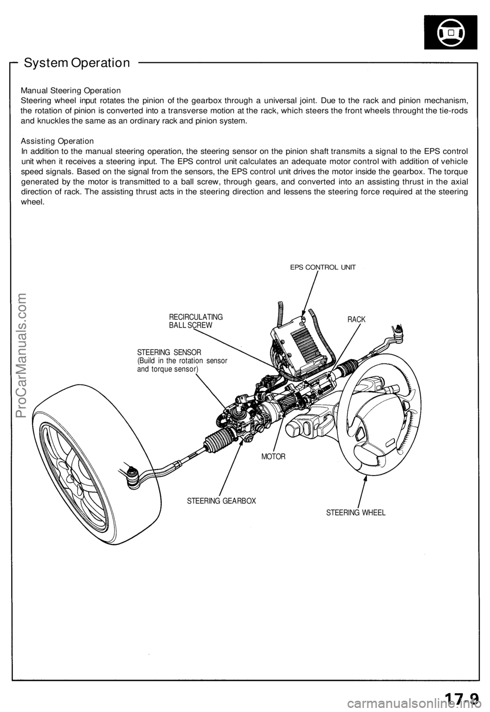
System Operation
Manual Steering Operation
Steering wheel input rotates the pinion of the gearbox through a universal joint. Due to the rack and pinion mechanism,
the rotation of pinion is converted into a transverse motion at the rack, which steers the front wheels throught the tie-rods
and knuckles the same as an ordinary rack and pinion system.
Assisting Operation
In addition to the manual steering operation, the steering sensor on the pinion shaft transmits a signal to the EPS control
unit when it receives a steering input. The EPS control unit calculates an adequate motor control with addition of vehicle
speed signals. Based on the signal from the sensors, the EPS control unit drives the motor inside the gearbox. The torque
generated by the motor is transmitted to a ball screw, through gears, and converted into an assisting thrust in the axial
direction of rack. The assisting thrust acts in the steering direction and lessens the steering force required at the steering
wheel.
EPS CONTROL UNIT
RECIRCULATING
BALL SCREW
STEERING WHEEL
RACK
STEERING SENSOR
(Build in the rotation sensor
and torque sensor)
MOTOR
STEERING GEARBOXProCarManuals.com
Page 410 of 1640
System Description
Function and Operation
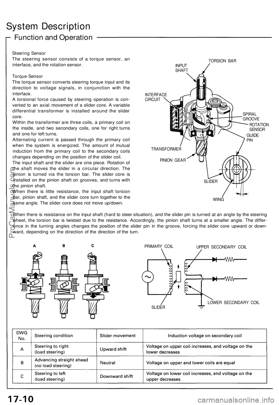
Steering Sensor
The steering sensor consists of a torque sensor, an
interface, and the rotation sensor.
Torque Sensor
The torque sensor converts steering torque input and its
direction to voltage signals, in conjunction with the
interface.
A torsional force caused by steering operation is con-
verted to an axial movement of a slider core. A variable
differential transformer is installed around the slider
core.
Within the transformer are three coils, a primary coil on
the inside, and two secondary coils, one for right turns
and one for left turns.
Alternating current is passed through the primary coil
when the system is energized. The amount of mutual
induction from the primary coil to the secondary coils
changes depending on the position of the slider coil.
The input shaft and the slider are one piece. Rotation of
the shaft moves the slider in a circular direction. The
pinion is turned via the torsion bar. The slider core is
installed on the pinion shaft on grooves, and turns with
the pinion shaft.
When there is little resistance, the input shaft torsion
bar, pinion shaft, and the slider core turn together to the
same angle. The slider core does not move up/down.
TORSION BAR
INPUT
SHAFT
INTERFACE
CIRCUIT
SPIRAL
GROOVE
ROTATION
SENSOR
GUIDE
PIN
TRANSFORMER
PINION GEAR
WING
When there is resistance on the input shaft (hard to steer situation), and the slider pin is turned at an angle by the steering
wheel, the torsion bar is twisted due to the resistance. Accordingly, the pinion shaft turns at a smaller angle. The differ-
ence in the turning angles changes the position of the slider pin in the groove, forcing the slider core upward or down-
ward, depending on the direction of the direction of the turn.
PRIMARY COIL
UPPER SECONDARY COIL
LOWER SECONDARY COIL
SLIDER
SLIDERProCarManuals.com
Page 411 of 1640
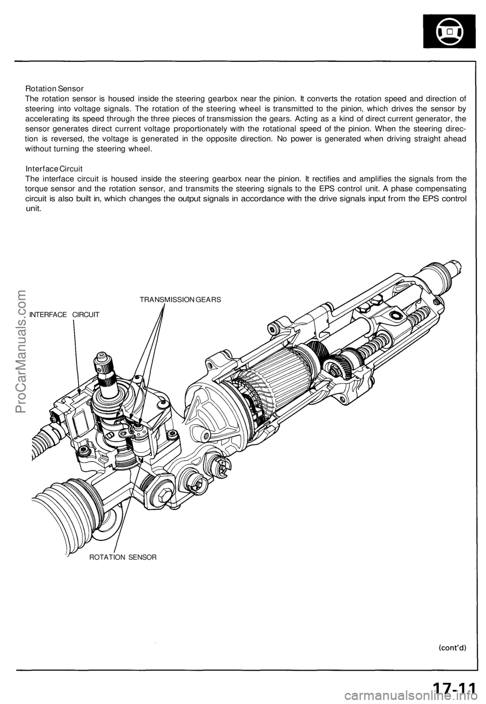
Rotation Sensor
The rotation sensor is housed inside the steering gearbox near the pinion. It converts the rotation speed and direction of
steering into voltage signals. The rotation of the steering wheel is transmitted to the pinion, which drives the sensor by
accelerating its speed through the three pieces of transmission the gears. Acting as a kind of direct current generator, the
sensor generates direct current voltage proportionately with the rotational speed of the pinion. When the steering direc-
tion is reversed, the voltage is generated in the opposite direction. No power is generated when driving straight ahead
without turning the steering wheel.
Interface Circuit
The interface circuit is housed inside the steering gearbox near the pinion. It rectifies and amplifies the signals from the
torque sensor and the rotation sensor, and transmits the steering signals to the EPS control unit. A phase compensating
circuit is also built in, which changes the output signals in accordance with the drive signals input from the EPS control
unit.
TRANSMISSION GEARS
INTERFACE CIRCUIT
ROTATION SENSORProCarManuals.com
Page 490 of 1640
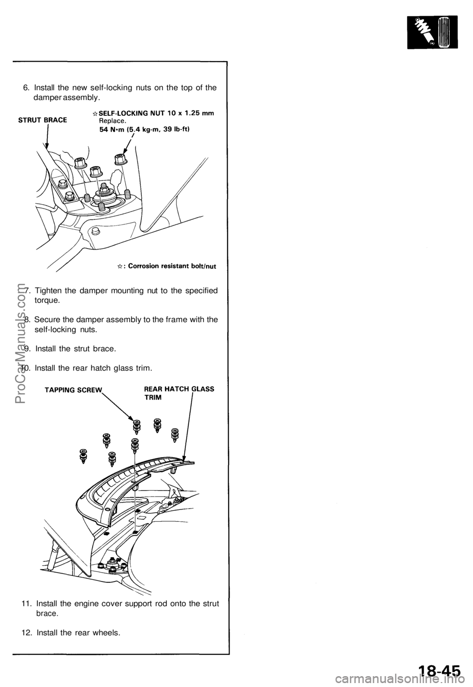
6. Install the new self-locking nuts on the top of the
damper assembly.
7. Tighten the damper mounting nut to the specified
torque.
8. Secure the damper assembly to the frame with the
self-locking nuts.
9. Install the strut brace.
10. Install the rear hatch glass trim.
11. Install the engine cover support rod onto the strut
brace.
12. Install the rear wheels.ProCarManuals.com
Page 492 of 1640
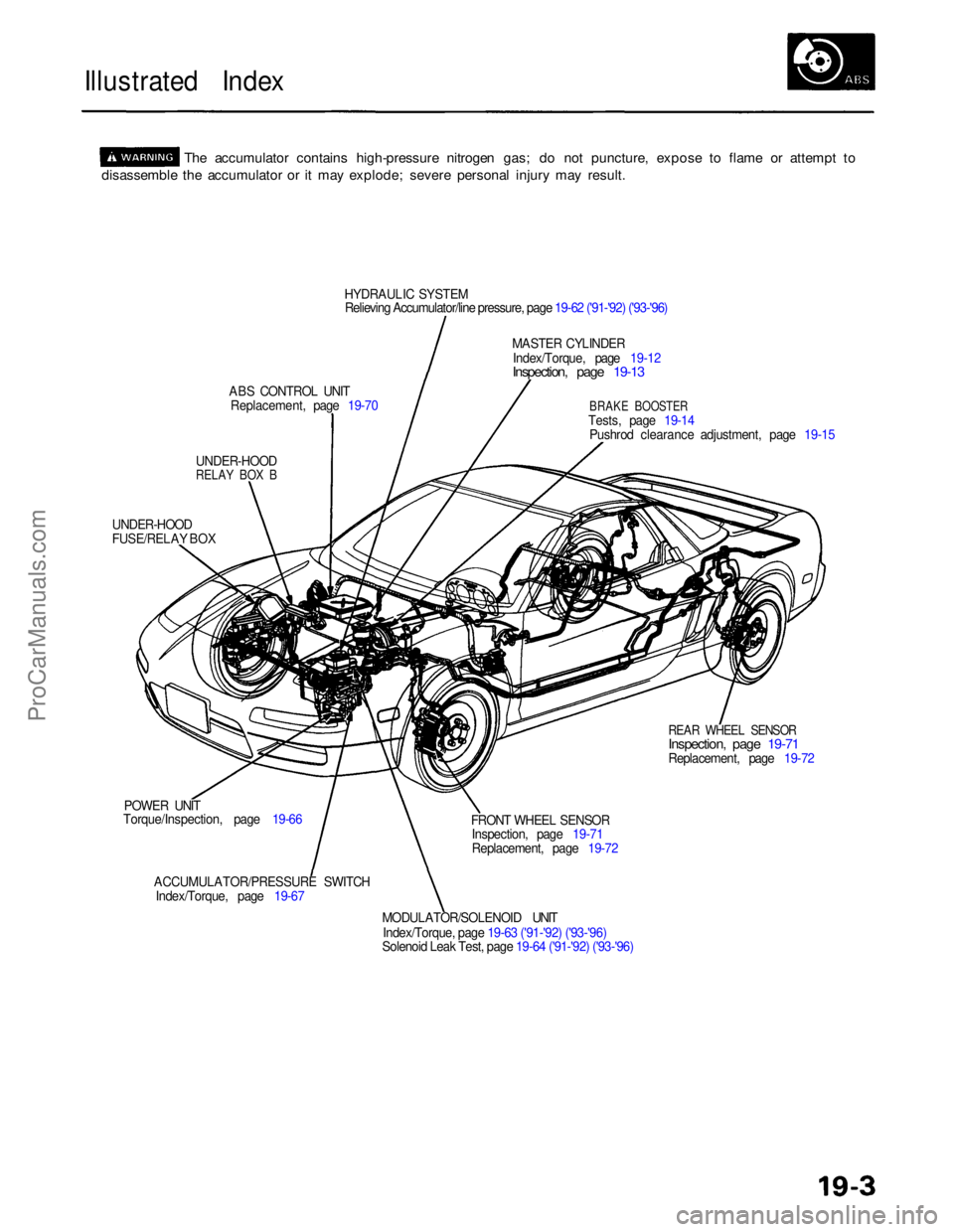
Illustrated Index
The accumulator contains high-pressure nitrogen gas; do not puncture, expose to flame or attempt to
disassemble the accumulator or it may explode; severe personal injury may result.
HYDRAULIC SYSTEM
Relieving Accumulator/line pressure, page 19-62 ('91-'92) ('93-'96)
MASTER CYLINDER
Index/Torque, page 19-12
Inspection, page 19-13
ABS CONTROL UNIT Replacement, page 19-70
BRAKE BOOSTER
Tests, page 19-14 Pushrod clearance adjustment, page 19-15
UNDER-HOOD
RELAY BOX B
UNDER-HOOD
FUSE/RELAY BOX
REAR WHEEL SENSOR
Inspection, page 19-71
Replacement, page 19-72
POWER UNIT
Torque/Inspection, page 19-66
ACCUMULATOR/PRESSURE SWITCHIndex/Torque, page 19-67 FRONT WHEEL SENSOR
Inspection, page 19-71
Replacement, page 19-72
MODULATOR/SOLENOID UNIT
Index/Torque, page 19-63 ('91-'92) ('93-'96)
Solenoid Leak Test, page 19-64 ('91-'92) ('93-'96)
ProCarManuals.com
Page 496 of 1640
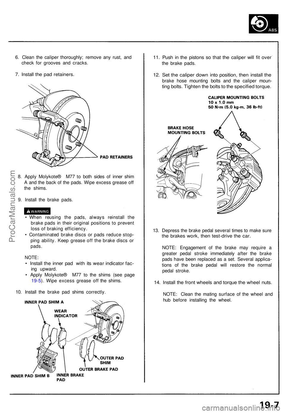
6. Clea n th e calipe r thoroughly ; remov e an y rust , an d
chec k fo r groove s an d cracks .
7. Instal l th e pa d retainers .
11. Pus h i n th e piston s s o tha t th e calipe r wil l fi t ove r
the brak e pads .
12. Se t th e calipe r dow n int o position , the n instal l th e
brak e hos e mountin g bolt s an d th e calipe r moun -
ting bolts . Tighte n th e bolt s to th e specifie d torque .
8. Appl y Molykote ® M7 7 t o bot h side s o f inne r shi m
A an d th e bac k o f th e pads . Wip e exces s greas e of f
th e shims .
9 . Instal l th e brak e pads .
• Whe n reusin g th e pads , alway s reinstal l th e
brak e pad s i n thei r origina l position s t o preven t
los s o f brakin g efficiency .
• Contaminate d brak e disc s o r pad s reduc e stop -
pin g ability . Kee p greas e of f th e brak e disc s o r
pads .
NOTE :
• Instal l th e inne r pa d wit h it s wea r indicato r fac -
ing upward .
• Appl y Molykote ® M7 7 t o th e shim s (se e pag e
19-5 ). Wip e exces s greas e of f th e shims .
10 . Instal l th e brak e pa d shim s correctly . 13
. Depres s th e brak e peda l severa l time s t o mak e sur e
the brake s work , the n test-driv e th e car .
NOTE : Engagemen t of the brak e ma y requir e a
greate r peda l strok e immediatel y afte r th e brak e
pad s hav e bee n replace d a s a set . Severa l applica -
tion s of the brak e peda l wil l restor e th e norma l
peda l stroke .
14. Instal l th e fron t wheel s an d torqu e th e whee l nuts .
NOTE : Clea n th e matin g surfac e o f th e whee l an d
hu b befor e installin g th e wheel .
ProCarManuals.com
Page 507 of 1640
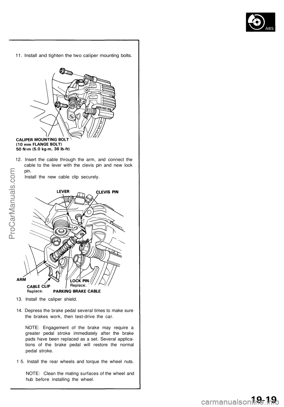
11. Install and tighten the two caliper mounting bolts.
12. Insert the cable through the arm, and connect the
cable to the lever with the clevis pin and new lock
pin.
Install the new cable clip securely.
13. Install the caliper shield.
14. Depress the brake pedal several times to make sure
the brakes work, then test-drive the car.
NOTE: Engagement of the brake may require a
greater pedal stroke immediately after the brake
pads have been replaced as a set. Several applica-
tions of the brake pedal will restore the normal
pedal stroke.
1 5. Install the rear wheels and torque the wheel nuts.
NOTE: Clean the mating surfaces of the wheel and
hub before installing the wheel.ProCarManuals.com