ACURA NSX 1997 Service Repair Manual
Manufacturer: ACURA, Model Year: 1997, Model line: NSX, Model: ACURA NSX 1997Pages: 1503, PDF Size: 57.08 MB
Page 1321 of 1503
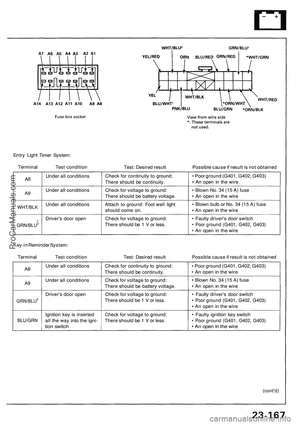
Entry Light Timer System:
Terminal Test condition
Test: Desired result
Possible cause if result is not obtained
A8
A9
WHT/BLK
GRN/BLU2
Under all conditions
Under all conditions
Under all conditions
Driver's door open
Check for continuity to ground:
There should be continuity.
Check for voltage to ground:
There should be battery voltage.
Attach to ground: Foot well light
should come on.
Check for voltage to ground:
There should be 1 V or less.
• Poor ground (G401, G402, G403)
• An open in the wire
• Blown No. 34 (15 A) fuse
• An open in the wire
• Blown bulb or No. 34 (15 A) fuse
• An open in the wire
• Faulty driver's door switch
• Poor ground (G401, G402, G403)
• An open in the wire
Key-in Reminder System:
Terminal Test condition
Test: Desired result
Possible cause if result is not obtained
A8
A9
GRN/BLU2
BLU/GRN
Under all conditions
Under all conditions
Driver's door open
Ignition key is inserted
all the way into the igni-
tion switch
Check for continuity to ground:
There should be continuity.
Check for voltage to ground:
There should be battery voltage.
Check for voltage to ground:
There should be 1 V or less.
Check for voltage to ground:
There should be 1 V or less.
• Poor ground (G401, G402, G403)
• An open in the wire
• Blown No. 34 (15 A) fuse
• An open in the wire
• Faulty driver's door switch
• Poor ground (G401, G402, G403)
• An open in the wire
• Faulty ignition key switch
• Poor ground (G401, G402, G403)
• An open in the wire
(cont'd)ProCarManuals.com
Page 1322 of 1503
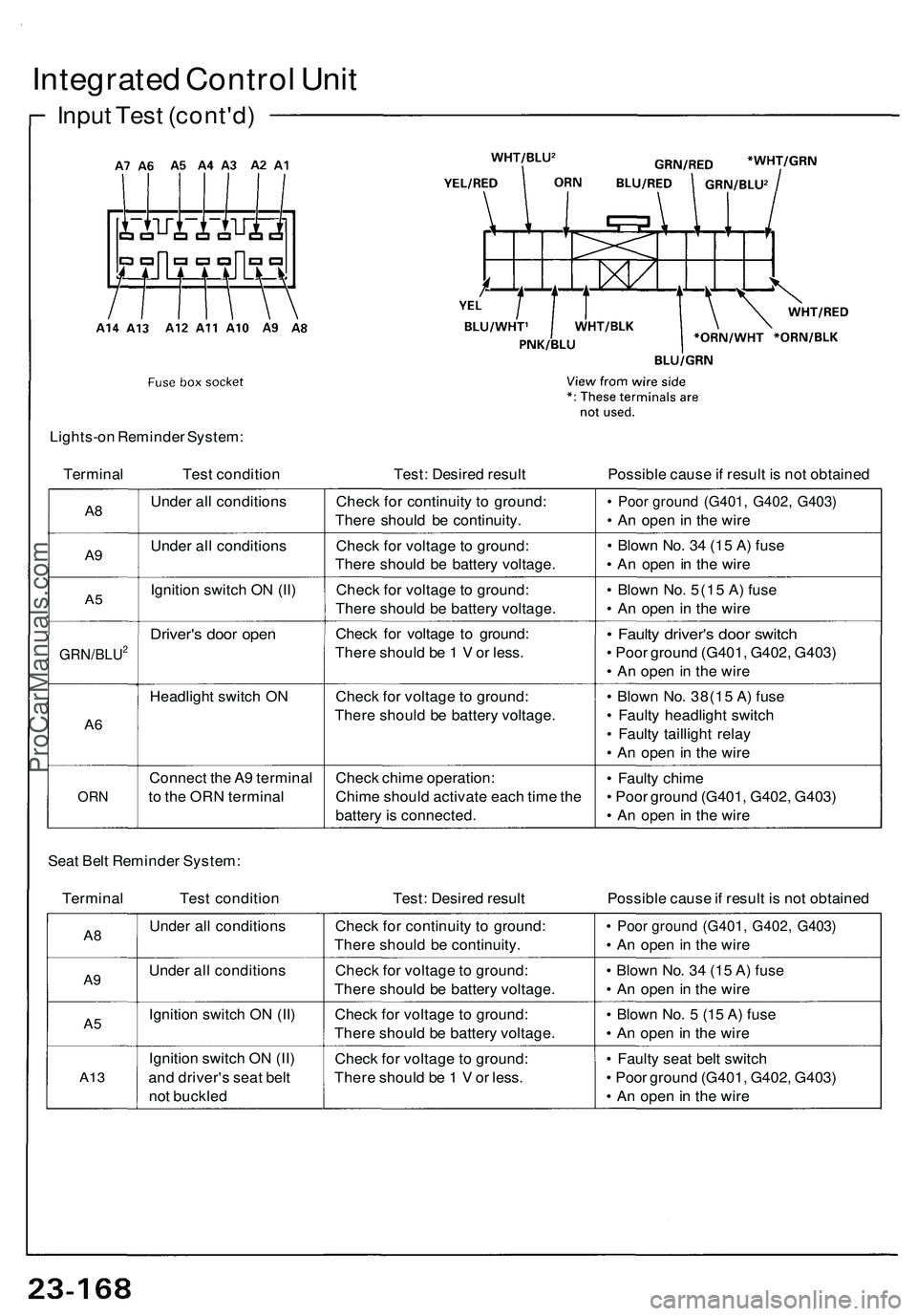
Integrated Control Unit
Input Test (cont'd)
Lights-on Reminder System:
Terminal
Test condition
Test: Desired result
Possible cause if result is not obtained
A8
A9
A5
GRN/BLU2
A6
ORN
Under all conditions
Under all conditions
Ignition switch ON (II)
Driver's door open
Headlight switch ON
Connect the A9 terminal
to the ORN terminal
Check for continuity to ground:
There should be continuity.
Check for voltage to ground:
There should be battery voltage.
Check for voltage to ground:
There should be battery voltage.
Check for voltage to ground:
There should be 1 V or less.
Check for voltage to ground:
There should be battery voltage.
Check chime operation:
Chime should activate each time the
battery is connected.
• Poor ground (G401, G402, G403)
• An open in the wire
• Blown No. 34 (15 A) fuse
• An open in the wire
• Blown No. 5(15 A) fuse
• An open in the wire
• Faulty driver's door switch
• Poor ground (G401, G402, G403)
• An open in the wire
• Blown No. 38(15 A) fuse
• Faulty headlight switch
• Faulty taillight relay
• An open in the wire
• Faulty chime
• Poor ground (G401, G402, G403)
• An open in the wire
Seat Belt Reminder System:
Terminal Test condition
Test: Desired result
Possible cause if result is not obtained
A8
A9
A5
A13
Under all conditions
Under all conditions
Ignition switch ON (II)
Ignition switch ON (II)
and driver's seat belt
not buckled
Check for continuity to ground:
There should be continuity.
Check for voltage to ground:
There should be battery voltage.
Check for voltage to ground:
There should be battery voltage.
Check for voltage to ground:
There should be 1 V or less.
• Poor ground (G401, G402, G403)
• An open in the wire
• Blown No. 34 (15 A) fuse
• An open in the wire
• Blown No. 5 (15 A) fuse
• An open in the wire
• Faulty seat belt switch
• Poor ground (G401, G402, G403)
• An open in the wireProCarManuals.com
Page 1323 of 1503
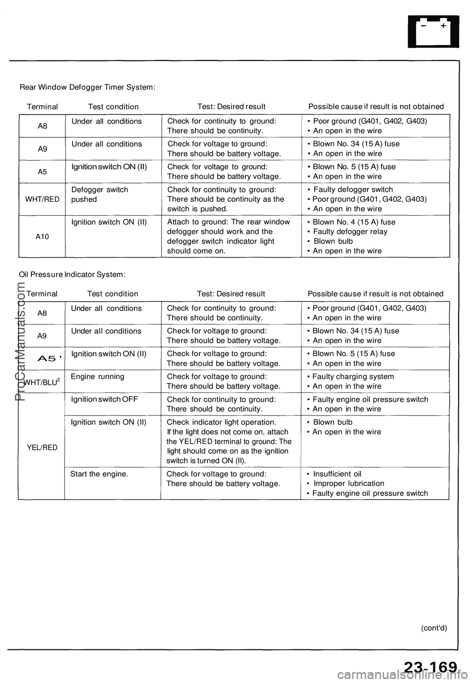
Rear Window Defogger Timer System:
Terminal Test condition
Test: Desired result
Possible cause if result is not obtained
A8
A9
A5
WHT/RED
A10
Under all conditions
Under all conditions
Ignition switch ON (II)
Defogger switch
pushed
Ignition switch ON (II)
Check for continuity to ground:
There should be continuity.
Check for voltage to ground:
There should be battery voltage.
Check for voltage to ground:
There should be battery voltage.
Check for continuity to ground:
There should be continuity as the
switch is pushed.
Attach to ground: The rear window
defogger should work and the
defogger switch indicator light
should come on.
• Poor ground (G401, G402, G403)
• An open in the wire
• Blown No. 34 (15 A) fuse
• An open in the wire
• Blown No. 5 (15 A) fuse
• An open in the wire
• Faulty defogger switch
• Poor ground (G401, G402, G403)
• An open in the wire
• Blown No. 4 (15 A) fuse
• Faulty defogger relay
• Blown bulb
• An open in the wire
Oil Pressure Indicator System:
Terminal Test condition
Test: Desired result
Possible cause if result is not obtained
A8
A9
A5 '
WHT/BLU2
YEL/RED
Under all conditions
Under all conditions
Ignition switch ON (II)
Engine running
Ignition switch OFF
Ignition switch ON (II)
Start the engine.
Check for continuity to ground:
There should be continuity.
Check for voltage to ground:
There should be battery voltage.
Check for voltage to ground:
There should be battery voltage.
Check for voltage to ground:
There should be battery voltage.
Check for continuity to ground:
There should be continuity.
Check indicator light operation.
If the light does not come on, attach
the YEL/RED terminal to ground: The
light should come on as the ignition
switch is turned ON (II).
Check for voltage to ground:
There should be battery voltage.
• Poor ground (G401, G402, G403)
• An open in the wire
• Blown No. 34 (15 A) fuse
• An open in the wire
• Blown No. 5 (15 A) fuse
• An open in the wire
• Faulty charging system
• An open in the wire
• Faulty engine oil pressure switch
• An open in the wire
• Blown bulb
• An open in the wire
• Insufficient oil
• Improper lubrication
• Faulty engine oil pressure switch
(cont'd)ProCarManuals.com
Page 1324 of 1503
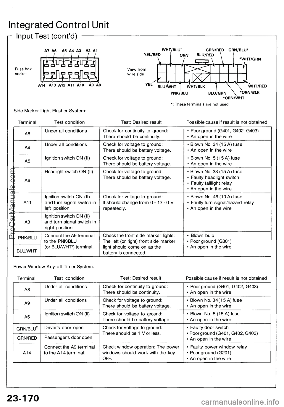
Integrated Contro l Uni t
Inpu t Tes t (cont'd )
Side Marke r Ligh t Flashe r System :
Termina l Tes
t conditio n Test: Desire d resul t Possible caus e if resul t i s no t obtaine d
A8
A9
A 5
A 6
A1 1
A3
PNK/BL U
BLU/WH T
Under al l condition s
Under al l condition s
Ignition switc h O N (II )
Headligh t switc h O N (II )
Ignitio n switc h O N (II )
and tur n signa l switc h in
lef t positio n
Ignition switc h O N (II )
an d tur n signa l switc h i n
righ t positio n
Connec t th e A 9 termina l
t o th e PNK/BL U
(o r BLU/WHT
1) terminal .Chec
k fo r continuit y t o ground :
Ther e shoul d b e continuity .
Chec k fo r voltag e t o ground :
Ther e shoul d b e batter y voltage .
Chec k fo r voltag e to ground :
Ther e shoul d b e batter y voltage .
Chec k fo r voltag e t o ground :
Ther e shoul d b e batter y voltage .
Chec k fo r voltag e t o ground :
It shoul d chang e fro m 0 - 1 2 - 0 V
repeatedly .
Chec k th e fron t sid e marke r lights :
Th e lef t (o r right ) fron t sid e marke r
ligh t shoul d com e o n a s th e
batter y is connected . •
Poo r groun d (G401 , G402 , G403 )
• A n ope n in th e wir e
• Blow n No . 3 4 (1 5 A ) fus e
• A n ope n in th e wir e
• Blow n No . 5 (1 5 A ) fus e
• A n ope n in th e wir e
• Blow n No . 3 8 (1 5 A ) fus e
• Fault y headligh t switc h
• Fault y tailligh t rela y
• A n ope n in th e wir e
• Blow n No . 4 6 (1 0 A ) fus e
• Fault y tur n signal/hazar d rela y
• A n ope n i n th e wir e
• Blow n bul b
• Poo r groun d (G301 )
• A n ope n in th e wir e
Powe r Windo w Key-of f Time r System :
Termina l Tes
t conditio n Test
: Desire d resul t
Possible caus e if resul t i s no t obtaine d
A8
A 9
A 5
GRN/BLU2
GRN/RE D
A14
Unde r al l condition s
Unde r al l condition s
Ignition switc h O N (II )
Driver' s doo r ope n
Passenger' s doo r ope n
Connec t th e A 9 termina l
to th e A1 4 terminal .
Check fo r continuit y t o ground :
Ther e shoul d b e continuity .
Chec k fo r voltag e t o ground :
Ther e shoul d b e batter y voltage .
Chec k fo r voltag e t o ground :
Ther e shoul d b e batter y voltage .
Chec k fo r voltag e t o ground :
Ther e shoul d b e 1 V or less .
Chec k windo w operation : Th e powe r
window s shoul d wor k wit h th e ke y
OFF .
• Poo r groun d (G401 , G402 , G403 )
• A n ope n i n th e wir e
• Blow n No . 34(1 5 A ) fus e
• A n ope n i n th e wir e
• Blow n No . 5 (1 5 A ) fus e
• A n ope n in th e wir e
• Fault y doo r switc h
• Poo r groun d (G401 , G402 , G403 )
• A n ope n in th e wir e
• Fault y powe r windo w rela y
• Poo r groun d (G201 )
• A n ope n in th e wir e
ProCarManuals.com
Page 1325 of 1503
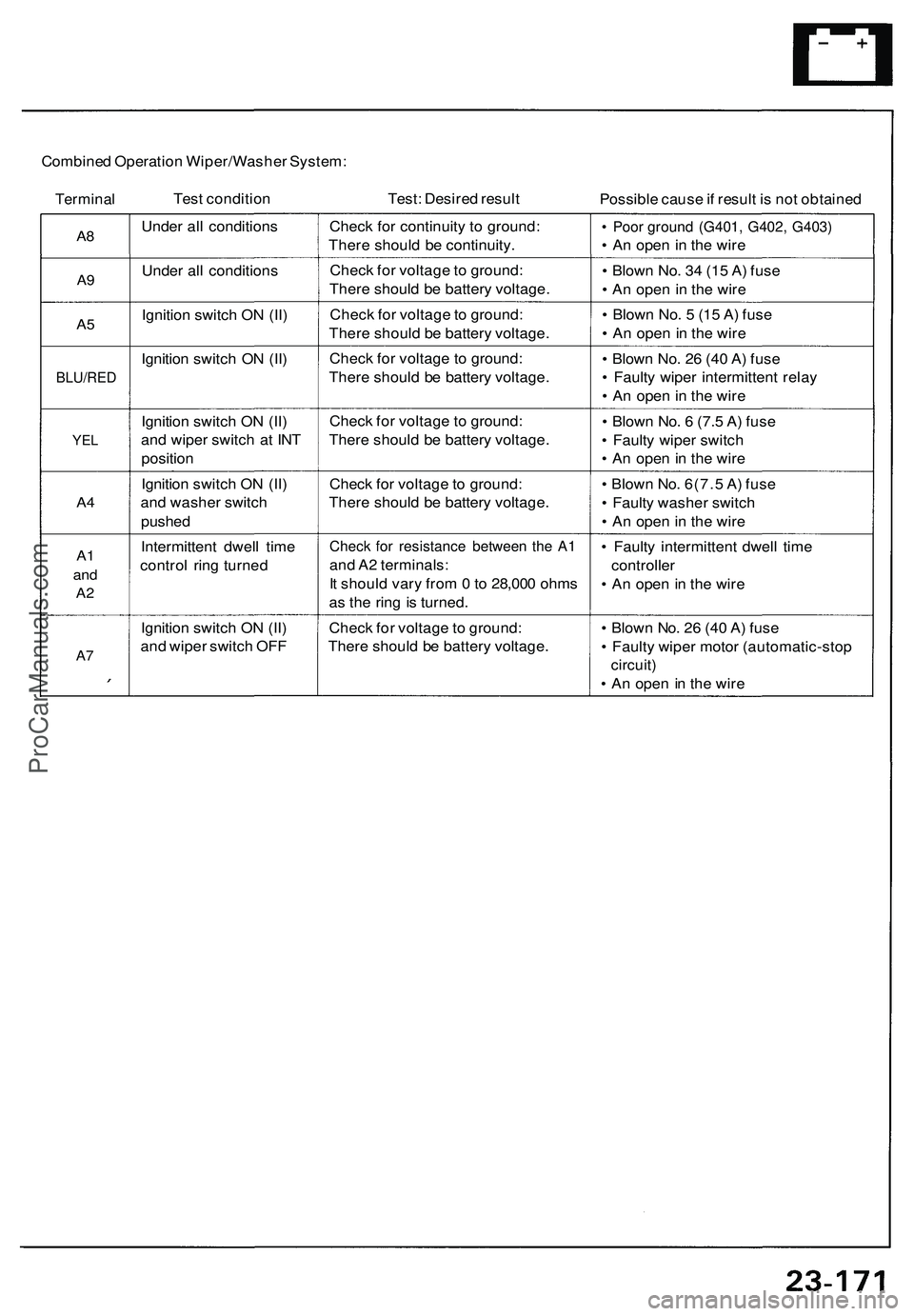
Combined Operation Wiper/Washer System:
Terminal
Test condition
Test: Desired result
Possible cause if result is not obtained
A8
A9
A5
BLU/RED
YEL
A4
A1
and
A2
A7
Under all conditions
Under all conditions
Ignition switch ON (II)
Ignition switch ON (II)
Ignition switch ON (II)
and wiper switch at INT
position
Ignition switch ON (II)
and washer switch
pushed
Intermittent dwell time
control ring turned
Ignition switch ON (II)
and wiper switch OFF
Check for continuity to ground:
There should be continuity.
Check for voltage to ground:
There should be battery voltage.
Check for voltage to ground:
There should be battery voltage.
Check for voltage to ground:
There should be battery voltage.
Check for voltage to ground:
There should be battery voltage.
Check for voltage to ground:
There should be battery voltage.
Check for resistance between the A1
and A2 terminals:
It should vary from 0 to 28,000 ohms
as the ring is turned.
Check for voltage to ground:
There should be battery voltage.
• Poor ground (G401, G402, G403)
• An open in the wire
• Blown No. 34 (15 A) fuse
• An open in the wire
• Blown No. 5 (15 A) fuse
• An open in the wire
• Blown No. 26 (40 A) fuse
• Faulty wiper intermittent relay
• An open in the wire
• Blown No. 6 (7.5 A) fuse
• Faulty wiper switch
• An open in the wire
• Blown No. 6(7.5 A) fuse
• Faulty washer switch
• An open in the wire
• Faulty intermittent dwell time
controller
• An open in the wire
• Blown No. 26 (40 A) fuse
• Faulty wiper motor (automatic-stop
circuit)
• An open in the wireProCarManuals.com
Page 1326 of 1503
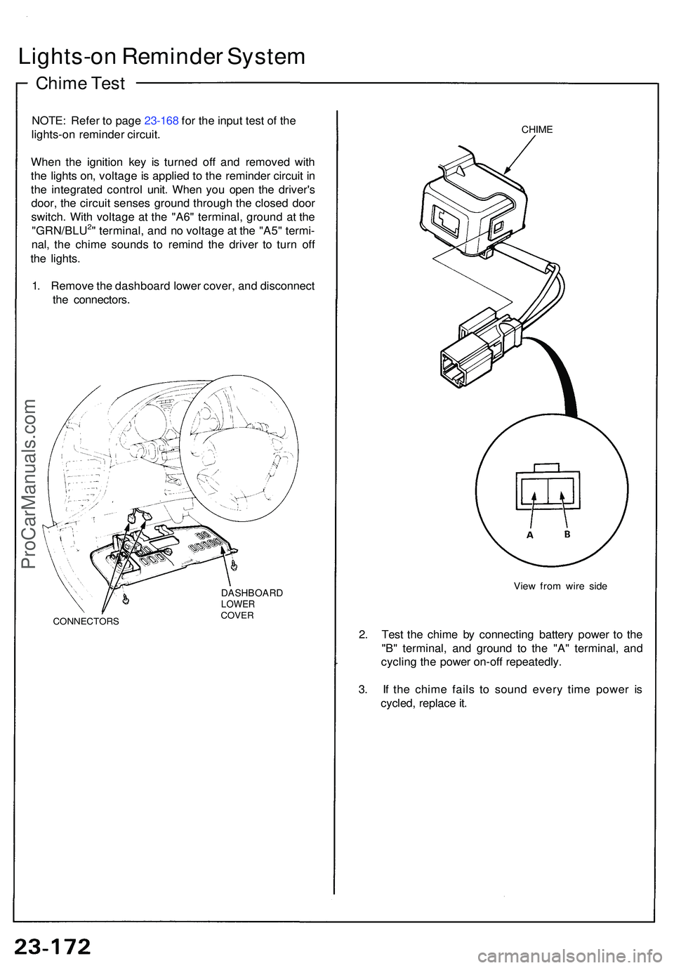
Lights-on Reminde r Syste m
Chime Tes t
NOTE : Refe r t o pag e 23-168 for the input test of the
lights-on reminde r circuit.
Whe n th e ignitio n ke y i s turne d of f an d remove d wit h
th e light s on , voltag e is applie d t o th e reminde r circui t i n
th e integrate d contro l unit . Whe n yo u ope n th e driver' s
door , th e circui t sense s groun d throug h th e close d doo r
switch . Wit h voltag e a t th e "A6 " terminal , groun d a t th e
"GRN/BLU
2" terminal , an d n o voltag e a t th e "A5 " termi -
nal , th e chim e sound s t o remin d th e drive r t o tur n of f
th e lights .
1 . Remov e th e dashboar d lowe r cover , an d disconnec t
th e connectors .
CONNECTOR S
DASHBOARDLOWERCOVER
CHIME
Vie w fro m wir e sid e
2. Tes t th e chim e b y connectin g batter y powe r t o th e
"B " terminal , an d groun d t o th e "A " terminal , an d
cyclin g th e powe r on-of f repeatedly .
3 . I f th e chim e fail s t o soun d ever y tim e powe r i s
cycled , replac e it .
ProCarManuals.com
Page 1327 of 1503
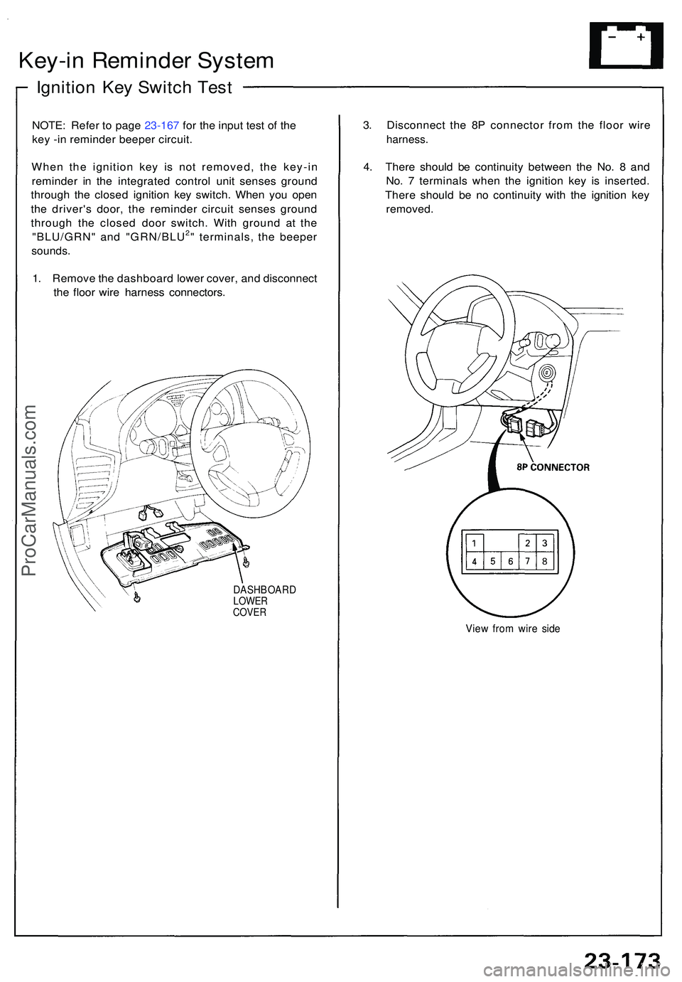
Key-in Reminde r Syste m
Ignitio n Ke y Switc h Tes t
NOTE : Refe r t o pag e 23-167 for the input test of the
key -in reminder beeper circuit.
Whe n th e ignitio n ke y i s no t removed , th e key-i n
reminde r i n th e integrate d contro l uni t sense s groun d
throug h th e close d ignitio n ke y switch . Whe n yo u ope n
th e driver' s door , th e reminde r circui t sense s groun d
throug h th e close d doo r switch . Wit h groun d a t th e
"BLU/GRN " an d "GRN/BLU
2" terminals , th e beepe r
sounds.
1. Remov e th e dashboar d lowe r cover , an d disconnec t
th e floo r wir e harnes s connectors .
DASHBOAR DLOWERCOVER
3. Disconnec t th e 8 P connecto r fro m th e floo r wir e
harness .
4. Ther e shoul d b e continuit y betwee n th e No . 8 an d
No . 7 terminal s whe n th e ignitio n ke y i s inserted .
Ther e shoul d b e n o continuit y wit h th e ignitio n ke y
removed .
View fro m wir e sid e
ProCarManuals.com
Page 1328 of 1503
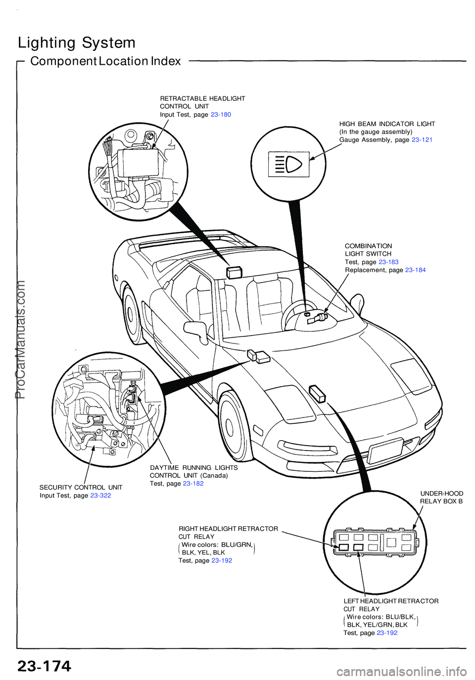
Lighting Syste m
Componen t Locatio n Inde x
RETRACTABL E HEADLIGH TCONTROL UNI T
Inpu t Test , pag e 23-18 0
HIGH BEA M INDICATO R LIGH T
(I n th e gaug e assembly )
Gaug e Assembly , pag e 23-12 1
COMBINATIO NLIGHT SWITC H
Test , pag e 23-18 3
Replacement , pag e 23-18 4
DAYTIM E RUNNIN G LIGHT S
CONTRO L UNI T (Canada )
Test , pag e 23-18 2
SECURIT Y CONTRO L UNI T
Inpu t Test , pag e 23-322 UNDER-HOO
D
RELA Y BO X B
RIGH T HEADLIGH T RETRACTO R
CUT RELA YWire colors : BLU/GRN ,BLK, YEL , BLKTest , pag e 23-19 2
LEFT HEADLIGH T RETRACTO R
CUT RELA YWire colors : BLU/BLK ,BLK, YEL/GRN , BL KTest , pag e 23-19 2
ProCarManuals.com
Page 1329 of 1503
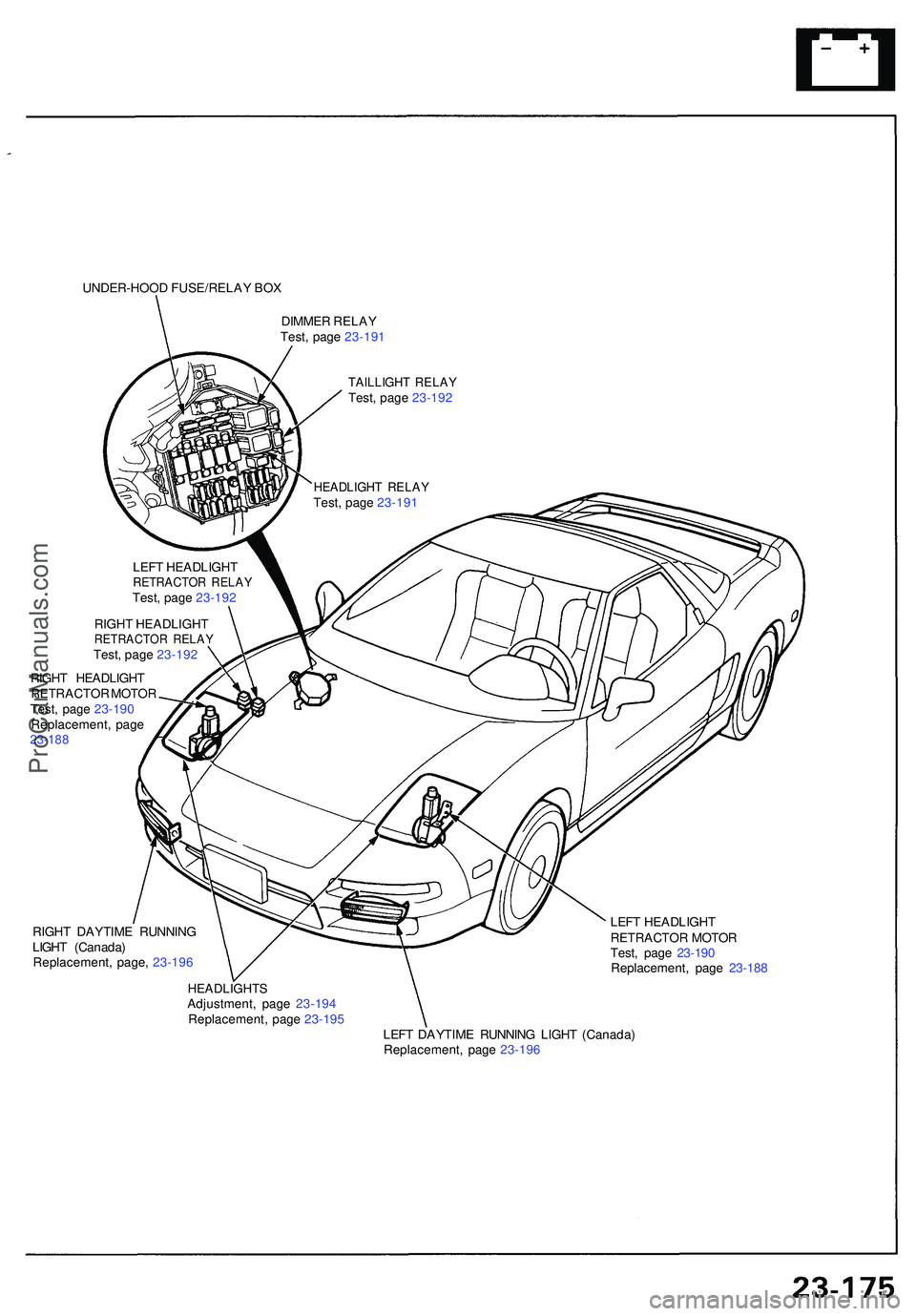
UNDER-HOOD FUSE/RELA Y BO X
DIMME R RELA Y
Test , pag e 23-19 1
TAILLIGH T RELA YTest, pag e 23-19 2
RIGH T HEADLIGH T
RETRACTO R MOTO R
Test , pag e 23-190
Replacement , pag e
23-18 8
HEADLIGH T RELA YTest, pag e 23-19 1
LEF T HEADLIGH T
RETRACTO R RELA YTest, pag e 23-19 2
RIGH T HEADLIGH T
RETRACTO R RELA YTest, pag e 23-19 2
RIGH T DAYTIM E RUNNIN G
LIGH T (Canada )
Replacement , page , 23-19 6 LEF
T HEADLIGH T
RETRACTO R MOTO R
Test , pag e 23-19 0
Replacement , pag e 23-18 8
HEADLIGHT SAdjustment, pag e 23-19 4
Replacement , pag e 23-19 5
LEFT DAYTIM E RUNNIN G LIGH T (Canada )
Replacement , pag e 23-19 6
ProCarManuals.com
Page 1330 of 1503
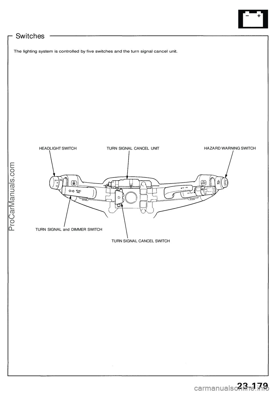
Switches
The lighting system is controlled by five switches and the turn signal cancel unit.
HEADLIGHT SWITCH
HAZARD WARNING SWITCH
TURN SIGNAL and DIMMER SWITCH
TURN SIGNAL CANCEL SWITCH
TURN SIGNAL CANCEL UNITProCarManuals.com