ACURA NSX 1997 Service Repair Manual
Manufacturer: ACURA, Model Year: 1997,
Model line: NSX,
Model: ACURA NSX 1997
Pages: 1503, PDF Size: 57.08 MB
ACURA NSX 1997 Service Repair Manual
NSX 1997
ACURA
ACURA
https://www.carmanualsonline.info/img/32/56989/w960_56989-0.png
ACURA NSX 1997 Service Repair Manual
Trending: OBD port, alarm, cruise control, steering, radio controls, roof rack, air suspension
Page 1281 of 1503
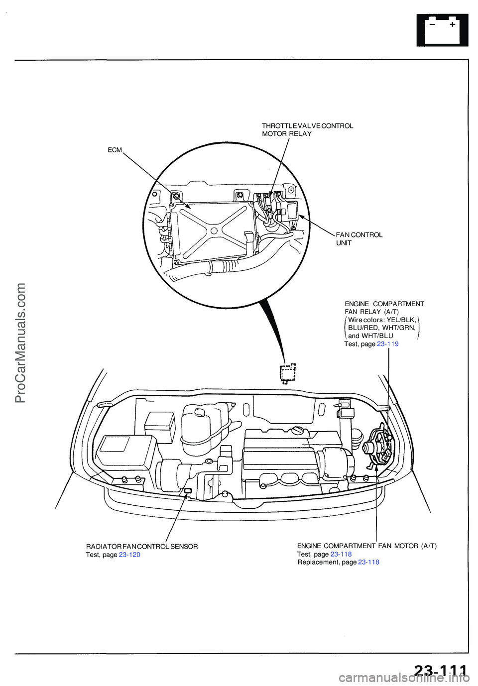
THROTTLE VALV E CONTRO L
MOTO R RELA Y
ECM
FAN CONTRO LUNIT
RADIATO R FA N CONTRO L SENSO R
Test , pag e 23-12 0 ENGIN
E COMPARTMEN T FA N MOTO R (A/T )
Test , pag e 23-11 8
Replacement , pag e 23-11 8
ENGIN
E COMPARTMEN T
FAN RELA Y (A/T )Wire colors : YEL/BLK ,
BLU/RED , WHT/GRN ,
and WHT/BL U
Test , pag e 23-11 9
ProCarManuals.com
Page 1282 of 1503
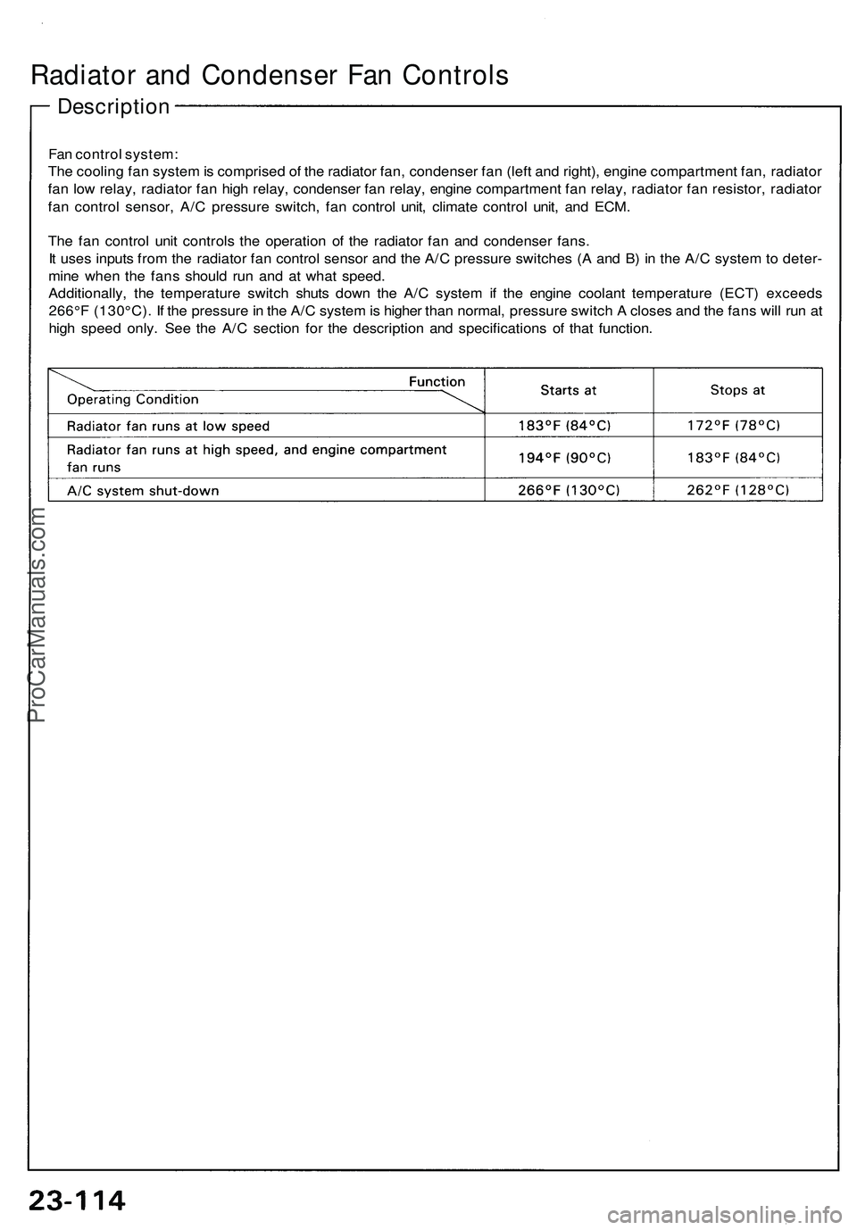
Radiator and Condenser Fan Controls
Description
Fan control system:
The cooling fan system is comprised of the radiator fan, condenser fan (left and right), engine compartment fan, radiator
fan low relay, radiator fan high relay, condenser fan relay, engine compartment fan relay, radiator fan resistor, radiator
fan control sensor, A/C pressure switch, fan control unit, climate control unit, and ECM.
The fan control unit controls the operation of the radiator fan and condenser fans.
It uses inputs from the radiator fan control sensor and the A/C pressure switches (A and B) in the A/C system to deter-
mine when the fans should run and at what speed.
Additionally, the temperature switch shuts down the A/C system if the engine coolant temperature (ECT) exceeds
266°F (130°C). If the pressure in the A/C system is higher than normal, pressure switch A closes and the fans will run at
high speed only. See the A/C section for the description and specifications of that function.ProCarManuals.com
Page 1283 of 1503
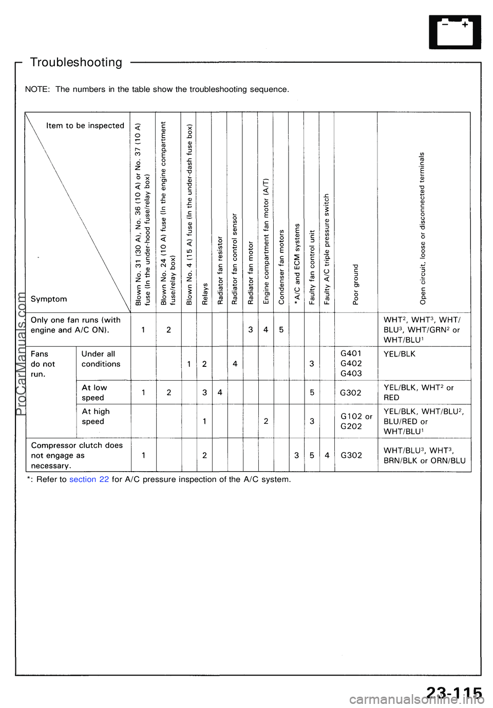
NOTE: Th e number s i n th e tabl e sho w th e troubleshootin g sequence .
Troubleshootin g
*: Refe r t o sectio n 2 2 fo r A/ C pressur e inspectio n o f th e A/ C system .
ProCarManuals.com
Page 1284 of 1503
Radiator and Condenser Fan Controls
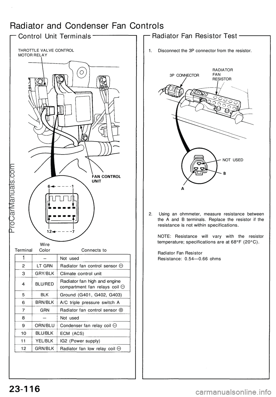
Control Unit Terminals
THROTTLE VALVE CONTROL
MOTOR RELAY
Wire
Terminal Color
Connects to
1
2
3
4
5
6
7
8
9
10
11
12
-
LT GRN
GRY/BLK
BLU/RED
BLK
BRN/BLK
GRN
—
ORN/BLU
BLU/BLK
YEL/BLK
GRN/BLK
Not used
Radiator fan control sensor
Climate control unit
Radiator fan high and engine
compartment fan relays coil
Ground (G401, G402, G403)
A/C triple pressure switch A
Radiator fan control sensor
Not used
Condenser fan relay coil
ECM
(ACS)
IG2 (Power supply)
Radiator fan low relay coil
1. Disconnect the 3P connector from the resistor.
3P CONNECTOR
RADIATOR
FAN
RESISTOR
NOT USED
2. Using an ohmmeter, measure resistance between
the A and B terminals. Replace the resistor if the
resistance is not within specifications.
NOTE: Resistance will vary with the resistor
temperature; specifications are at 68°F (20°C).
Radiator Fan Resistor
Resistance: 0.54—0.66 ohms
Radiator Fan Resistor TestProCarManuals.com
Page 1285 of 1503
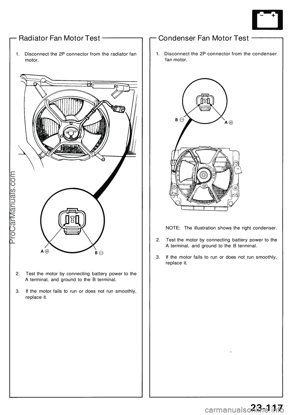
Radiator Fan Motor Test
1. Disconnect the 2P connector from the radiator fan
motor.
2. Test the motor by connecting battery power to the
A terminal, and ground to the B terminal.
3. If the motor fails to run or does not run smoothly,
replace it.
Condenser Fan Motor Test
1. Disconnect the 2P connector from the condenser
fan motor.
NOTE: The illustration shows the right condenser.
2. Test the motor by connecting battery power to the
A terminal, and ground to the B terminal.
3. If the motor fails to run or does not run smoothly,
replace it.ProCarManuals.com
Page 1286 of 1503
Radiator and Condenser Fan Controls
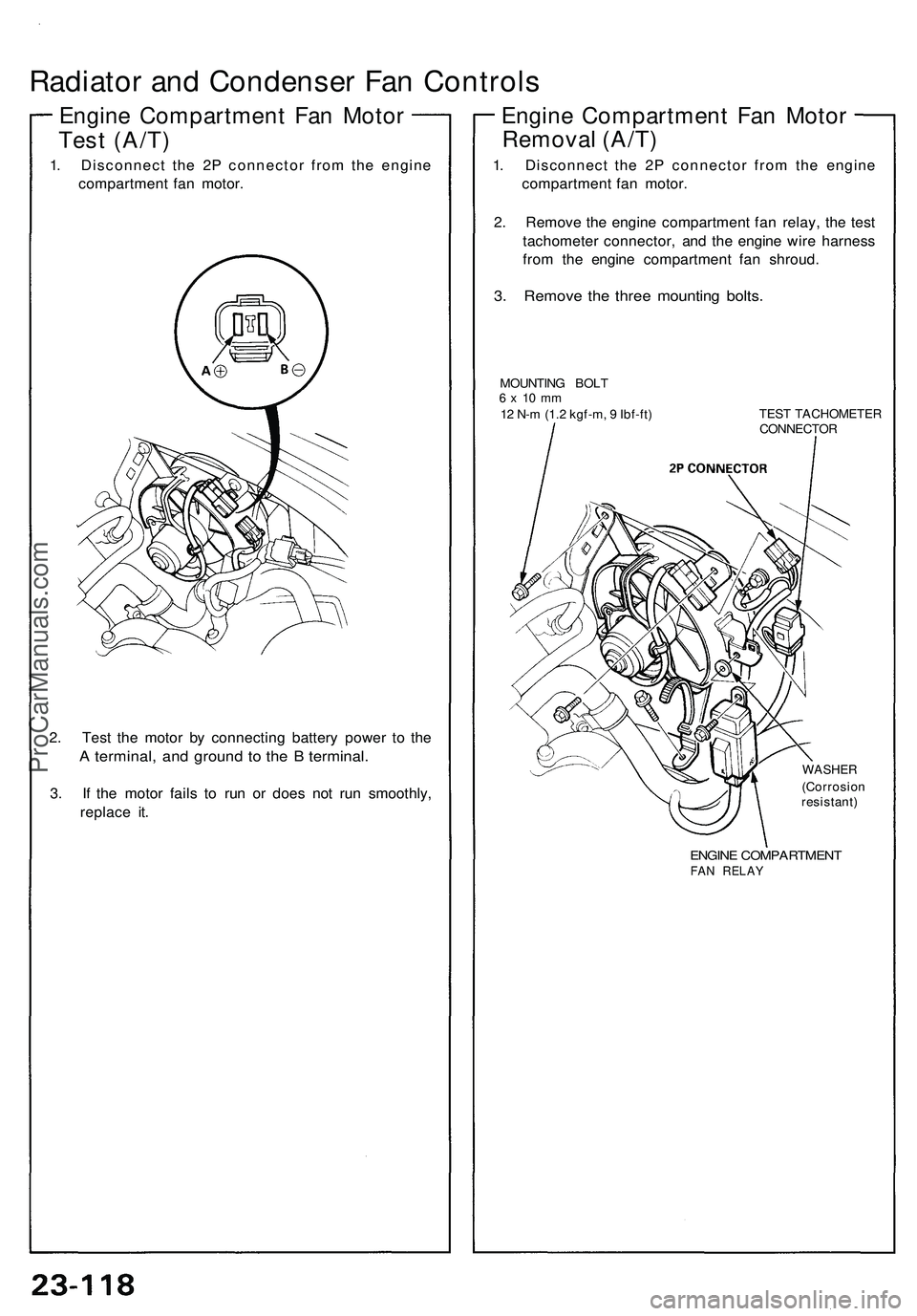
Engine Compartment Fan Motor
Test (A/T)
1. Disconnect the 2P connector from the engine
compartment fan motor.
2. Test the motor by connecting battery power to the
A terminal, and ground to the B terminal.
3. If the motor fails to run or does not run smoothly,
replace it.
Engine Compartment Fan Motor
Removal (A/T)
1. Disconnect the 2P connector from the engine
compartment fan motor.
2. Remove the engine compartment fan relay, the test
tachometer connector, and the engine wire harness
from the engine compartment fan shroud.
3. Remove the three mounting bolts.
MOUNTING BOLT
6 x 10 mm
12 N-m (1.2 kgf-m, 9 Ibf-ft)
TEST TACHOMETER
CONNECTOR
WASHER
(Corrosion
resistant)
ENGINE COMPARTMENT
FAN RELAYProCarManuals.com
Page 1287 of 1503
Fan Relay Tests
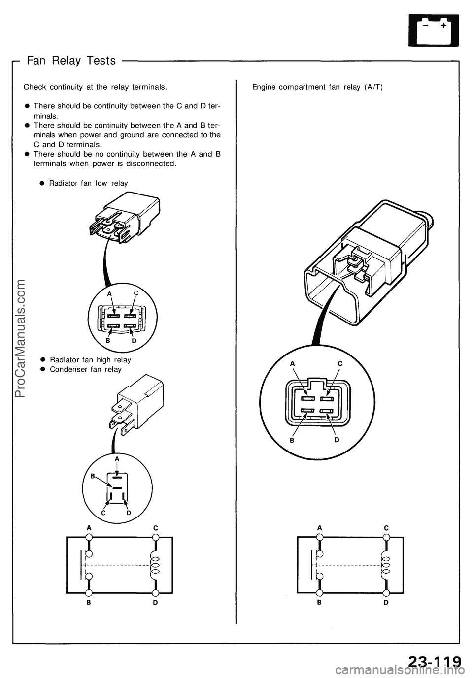
Check continuity at the relay terminals.
There should be continuity between the C and D ter-
minals.
There should be continuity between the A and B ter-
minals when power and ground are connected to the
C and D terminals.
There should be no continuity between the A and B
terminals when power is disconnected.
Radiator fan low relay
Engine compartment fan relay (A/T)
Radiator fan high relay
Condenser fan relayProCarManuals.com
Page 1288 of 1503
Radiator an d Condense r Fa n Control s
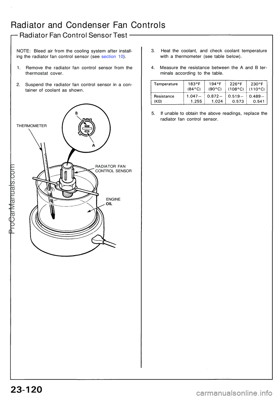
Radiator Fa n Contro l Senso r Tes t
NOTE : Blee d ai r fro m th e coolin g syste m afte r install -
in g th e radiato r fa n contro l senso r (se e sectio n 10 ).
1 . Remov e th e radiato r fa n contro l senso r fro m th e
thermosta t cover .
2 . Suspen d th e radiato r fa n contro l senso r i n a con -
taine r o f coolan t a s shown .
THERMOMETE R
RADIATOR FA N
CONTRO L SENSO R
ENGIN E
3. Hea t th e coolant , an d chec k coolan t temperatur e
wit h a thermomete r (se e tabl e below) .
4 . Measur e th e resistanc e betwee n th e A an d B ter -
minal s accordin g t o th e table .
5 . I f unabl e t o obtai n th e abov e readings , replac e th e
radiato r fa n contro l sensor .
ProCarManuals.com
Page 1289 of 1503
Gauge Assembl y
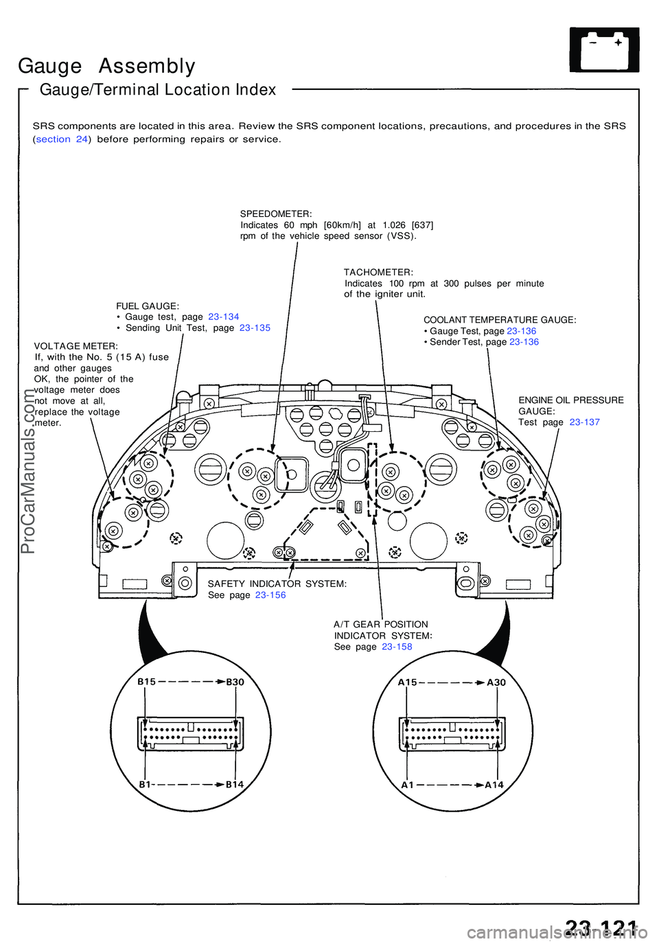
Gauge/Terminal Location Index
SRS component s ar e locate d in thi s area . Revie w th e SR S componen t locations , precautions , an d procedure s in th e SR S
(sectio n 24 ) befor e performin g repair s o r service .
SPEEDOMETER :Indicates 6 0 mp h [60km/h ] a t 1.02 6 [637 ]
rp m o f th e vehicl e spee d senso r (VSS) .
FUE L GAUGE :
• Gaug e test , pag e 23-13 4
• Sendin g Uni t Test , pag e 23-13 5
VOLTAG E METER :
If, wit h th e No . 5 (1 5 A ) fus eand othe r gauge s
OK , th e pointe r o f th e
voltag e mete r doe s
no t mov e a t all ,
replac e th e voltag e
meter .
TACHOMETER :Indicates 10 0 rp m a t 30 0 pulse s pe r minut eof th e ignite r unit .
COOLAN T TEMPERATUR E GAUGE :• Gaug e Test , pag e 23-13 6
• Sende r Test , pag e 23-13 6
SAFET Y INDICATO R SYSTEM :
Se e pag e 23-156 ENGIN
E OI L PRESSUR E
GAUGE:Test pag e 23-13 7
A/ T GEA R POSITIO N
INDICATO R SYSTE M
Se e pag e 23-158
ProCarManuals.com
Page 1290 of 1503
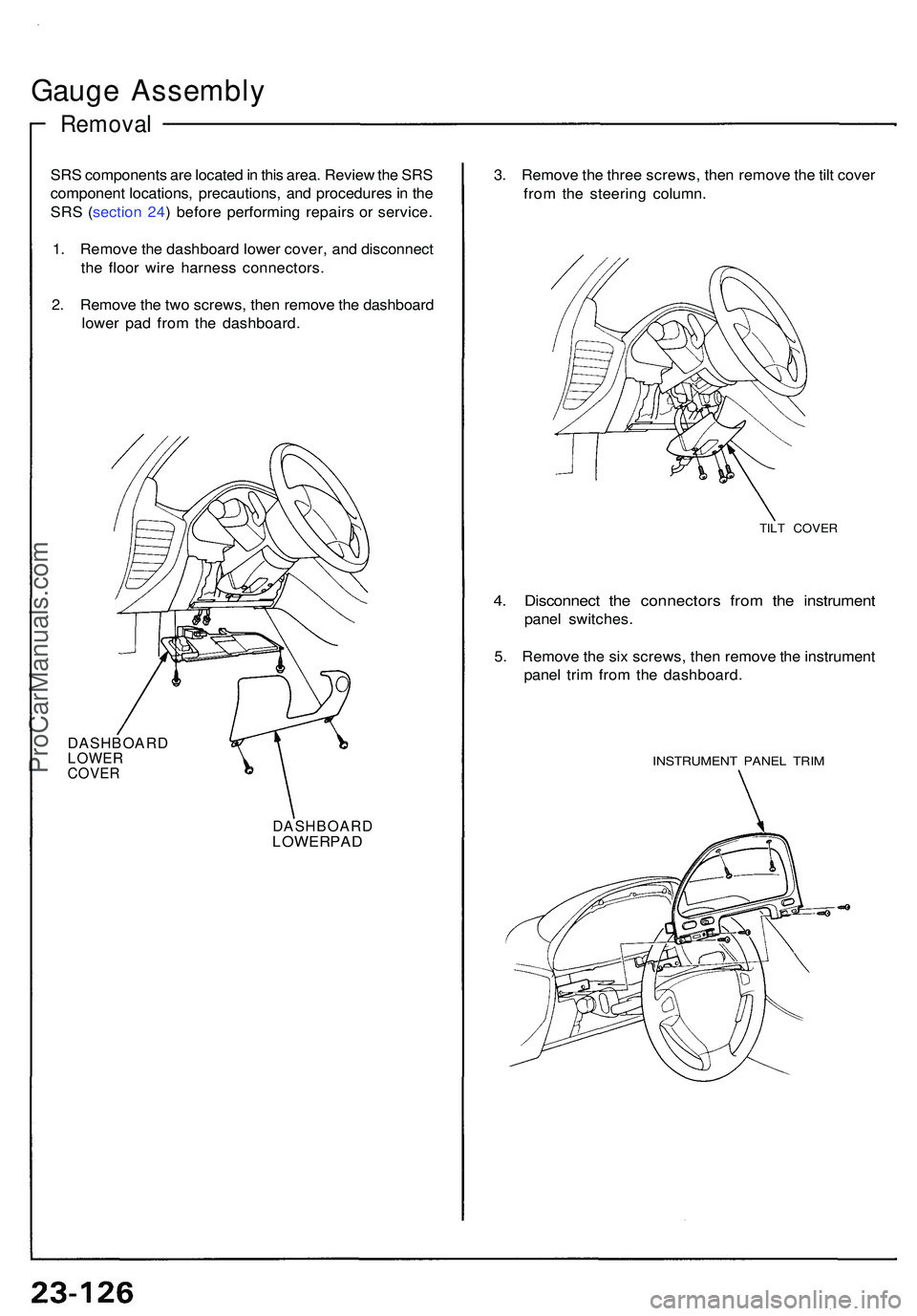
Gauge Assembl y
Removal
SRS component s ar e locate d in thi s area . Revie w th e SR S
componen t locations , precautions , an d procedure s in th e
SR S ( sectio n 24 ) befor e performin g repair s o r service .
1 . Remov e th e dashboar d lowe r cover , an d disconnec t
th e floo r wir e harnes s connectors .
2 . Remov e th e tw o screws , the n remov e th e dashboar d
lowe r pa d fro m th e dashboard .
DASHBOAR DLOWERCOVER
DASHBOAR DLOWER PA D 3
. Remov e th e thre e screws , the n remov e th e til t cove r
fro m th e steerin g column .
TILT COVE R
4. Disconnec t th e connector s fro m th e instrumen t
panel switches .
5 . Remov e th e si x screws , the n remov e th e instrumen t
pane l tri m fro m th e dashboard .
INSTRUMEN T PANE L TRI M
ProCarManuals.com
Trending: water pump, oil temperature, bulb, gearbox, spark plugs, trunk, lights
