tow ACURA NSX 1997 Service Repair Manual
[x] Cancel search | Manufacturer: ACURA, Model Year: 1997, Model line: NSX, Model: ACURA NSX 1997Pages: 1503, PDF Size: 57.08 MB
Page 156 of 1503
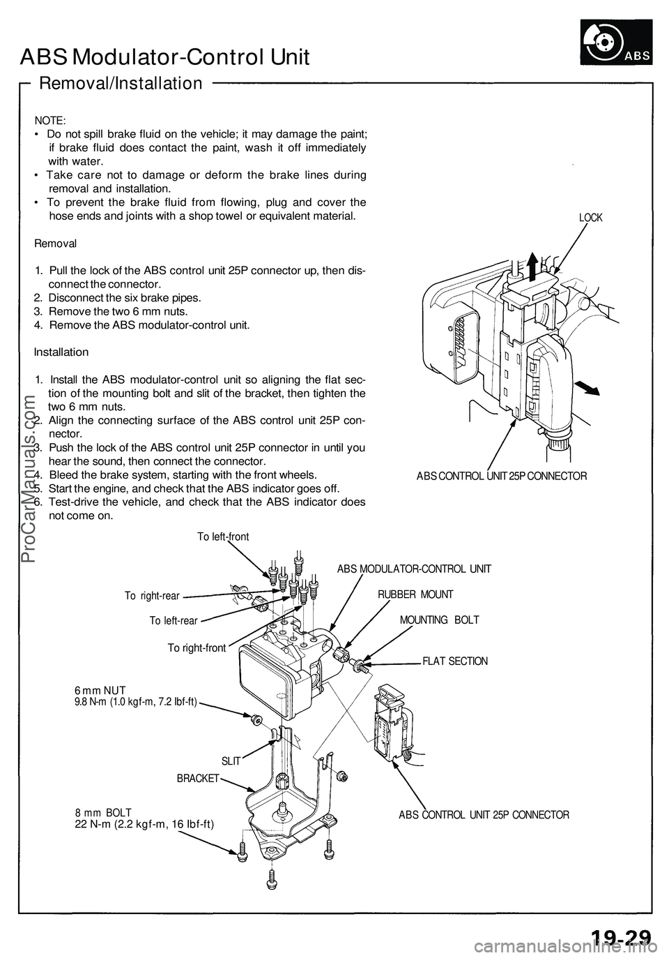
ABS Modulator-Contro l Uni t
Removal/Installatio n
NOTE:
• D o no t spil l brak e flui d o n th e vehicle ; i t ma y damag e th e paint ;
i f brak e flui d doe s contac t th e paint , was h i t of f immediatel y
wit h water .
• Tak e car e no t t o damag e o r defor m th e brak e line s durin g
remova l an d installation .
• T o preven t th e brak e flui d fro m flowing , plu g an d cove r th e
hos e end s an d joint s wit h a sho p towe l o r equivalen t material .
Removal
1. Pul l th e loc k o f th e AB S contro l uni t 25 P connecto r up , the n dis -
connec t th e connector .
2 . Disconnec t th e si x brak e pipes .
3 . Remov e th e tw o 6 m m nuts .
4 . Remov e th e AB S modulator-contro l unit .
Installatio n
1. Instal l th e AB S modulator-contro l uni t s o alignin g th e fla t sec -
tio n o f th e mountin g bol t an d sli t o f th e bracket , the n tighte n th e
tw o 6 m m nuts .
2 . Alig n th e connectin g surfac e o f th e AB S contro l uni t 25 P con -
nector .
3. Pus h th e loc k o f th e AB S contro l uni t 25 P connecto r i n unti l yo u
hea r th e sound , the n connec t th e connector .
4 . Blee d th e brak e system , startin g wit h th e fron t wheels .
5 . Star t th e engine , an d chec k tha t th e AB S indicato r goe s off .
6 . Test-driv e th e vehicle , an d chec k tha t th e AB S indicato r doe s
no t com e on .
LOC K
ABS CONTRO L UNI T 25 P CONNECTO R
To left-fron t
To right-rear
To left-rea r
To right-fron t
ABS MODULATOR-CONTRO L UNIT
RUBBE R MOUN T
MOUNTIN G BOL T
FLA T SECTIO N
6 m m NU T9.8 N- m (1. 0 kgf-m , 7. 2 Ibf-ft )
8 m m BOL T
22 N-m (2.2 kgf-m, 16 Ibf-ft) ABS CONTRO L UNI T 25 P CONNECTO R
SLI
T
BRACKE T
ProCarManuals.com
Page 285 of 1503
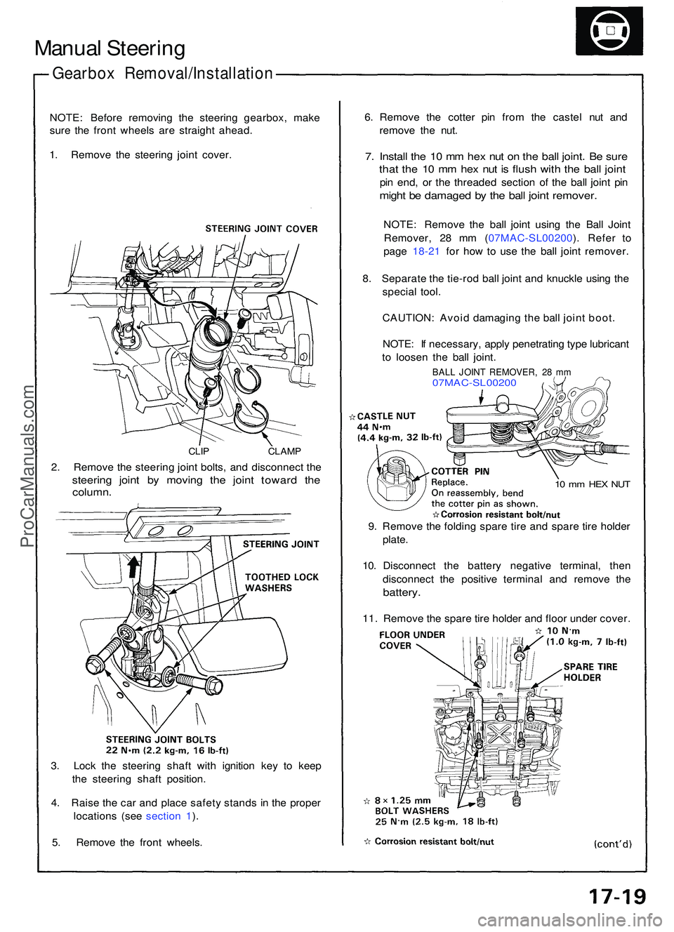
Manual Steerin g
Gearbo x Removal/Installatio n
NOTE: Befor e removin g th e steerin g gearbox , mak e
sur e th e fron t wheel s ar e straigh t ahead .
1 . Remov e th e steerin g join t cover .
CLIP CLAM P
2. Remov e th e steerin g join t bolts , an d disconnec t th e
steerin g join t b y movin g th e join t towar d th e
column .
3. Loc k th e steerin g shaf t wit h ignitio n ke y t o kee p
th e steerin g shaf t position .
4 . Rais e th e ca r an d plac e safet y stand s i n th e prope r
location s (se e sectio n 1 ).
5 . Remov e th e fron t wheels . 6
. Remov e th e cotte r pi n fro m th e caste l nu t an d
remov e th e nut .
7. Instal l th e 1 0 m m he x nu t o n th e bal l joint . B e sur e
that th e 1 0 m m he x nu t i s flus h wit h th e bal l join t
pin end , o r th e threade d sectio n o f th e bal l join t pi n
migh t b e damage d b y th e bal l join t remover .
NOTE: Remov e th e bal l join t usin g th e Bal l Join t
Remover , 2 8 m m ( 07MAC-SL00200 ). Refe r t o
pag e 18-2 1 fo r ho w to us e th e bal l join t remover .
8 . Separat e th e tie-ro d bal l join t an d knuckl e usin g th e
specia l tool .
CAUTION : Avoi d damagin g th e bal l join t boot .
NOTE : I f necessary , appl y penetratin g typ e lubrican t
t o loose n th e bal l joint .
BALL JOIN T REMOVER , 2 8 m m07MAC-SL0020 0
10 m m HE X NU T
9. Remov e th e foldin g spar e tir e an d spar e tir e holde r
plate .
10 . Disconnec t th e batter y negativ e terminal , the n
disconnec t th e positiv e termina l an d remov e th e
battery .
11. Remov e th e spar e tir e holde r an d floo r unde r cover .
ProCarManuals.com
Page 289 of 1503
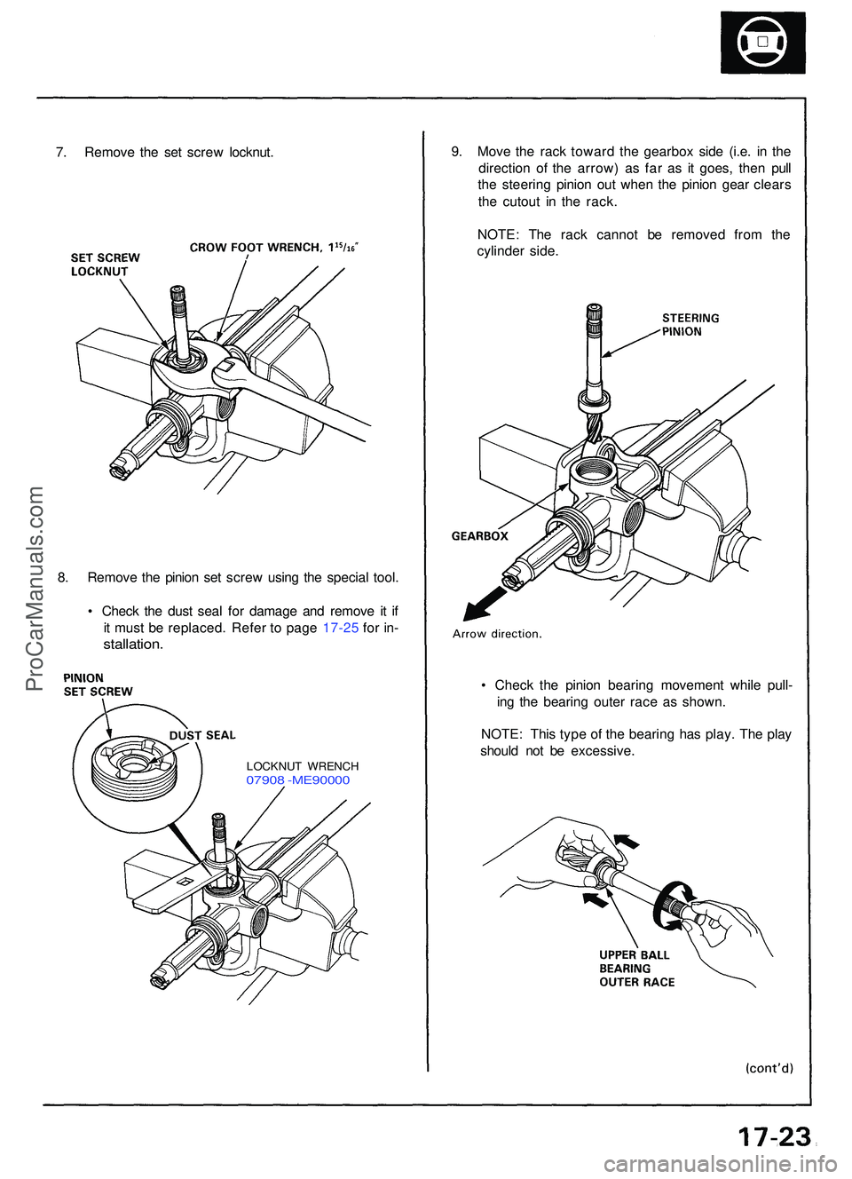
7. Remov e th e se t scre w locknut . 9
. Mov e th e rac k towar d th e gearbo x sid e (i.e . i n th e
directio n o f th e arrow ) a s fa r a s i t goes , the n pul l
th e steerin g pinio n ou t whe n th e pinio n gea r clear s
th e cutou t i n th e rack .
NOTE : Th e rac k canno t b e remove d fro m th e
cylinde r side .
8 . Remov e th e pinio n se t scre w usin g th e specia l tool .
• Chec k th e dus t sea l fo r damag e an d remov e i t i f
i t mus t b e replaced . Refe r t o pag e 17-2 5 fo r in -
stallation .
• Chec k th e pinio n bearin g movemen t whil e pull -
in g th e bearin g oute r rac e a s shown .
NOTE : Thi s typ e o f th e bearin g ha s play . Th e pla y
shoul d no t b e excessive .
LOCKNUT WRENC H07908 -ME9000 0
ProCarManuals.com
Page 290 of 1503
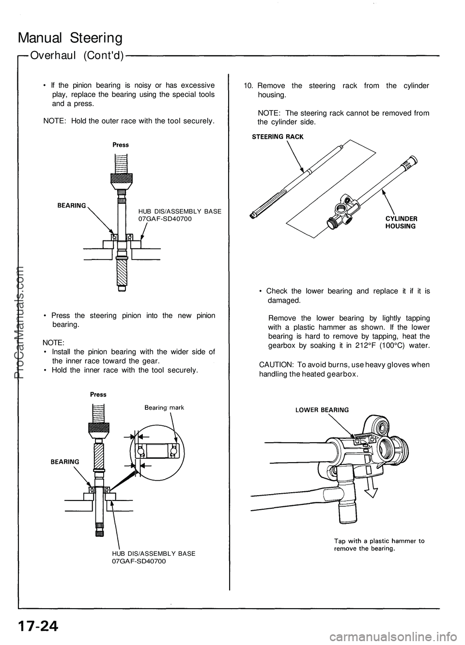
Overhaul (Cont'd )
Manual Steerin g
• I f th e pinio n bearin g i s nois y o r ha s excessiv e
play , replac e th e bearin g usin g th e specia l tool s
an d a press .
NOTE : Hol d th e oute r rac e wit h th e too l securely .10
. Remov e th e steerin g rac k fro m th e cylinde r
housing.
NOTE: Th e steerin g rac k canno t b e remove d fro m
th e cylinde r side .
HUB DIS/ASSEMBL Y BAS E07GAF-SD4070 0
• Chec k th e lowe r bearin g an d replac e i t i f i t i s
damaged .
Remov e th e lowe r bearin g b y lightl y tappin g
with a plasti c hamme r a s shown . I f th e lowe r
bearin g i s har d t o remov e b y tapping , hea t th e
gearbo x b y soakin g i t i n 212° F (100°C ) water .
CAUTION : T o avoi d burns , us e heav y glove s whe n
handlin g th e heate d gearbox .
•
Pres s th e steerin g pinio n int o th e ne w pinio n
bearing .
NOTE :
• Instal l th e pinio n bearin g wit h th e wide r sid e of
th e inne r rac e towar d th e gear .
• Hol d th e inne r rac e wit h th e too l securely .
HUB DIS/ASSEMBL Y BAS E07GAF-SD4070 0
ProCarManuals.com
Page 291 of 1503
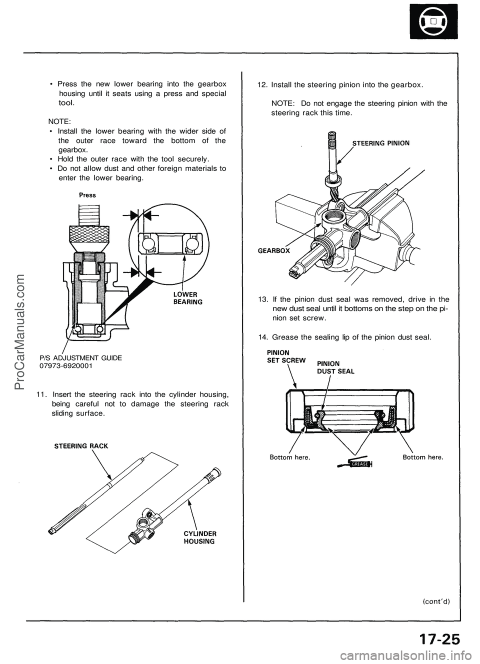
P/S ADJUSTMENT GUIDE
07973-6920001
11. Insert the steering rack into the cylinder housing,
being careful not to damage the steering rack
sliding surface.
13. If the pinion dust seal was removed, drive in the
new dust seal until it bottoms on the step on the pi-
nion set screw.
14. Grease the sealing lip of the pinion dust seal.
• Press the new lower bearing into the gearbox
housing until it seats using a press and special
tool.
NOTE:
• Install the lower bearing with the wider side of
the outer race toward the bottom of the
gearbox.
• Hold the outer race with the tool securely.
• Do not allow dust and other foreign materials to
enter the lower bearing.
12. Install the steering pinion into the gearbox.
NOTE: Do not engage the steering pinion with the
steering rack this time.ProCarManuals.com
Page 348 of 1503
Fuel Suppl y Syste m
Fuel Injector s (cont'd )
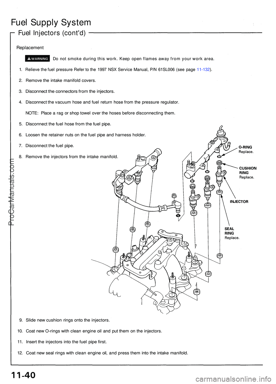
Replacemen t
Do no t smok e durin g thi s work . Kee p ope n flame s awa y fro m you r wor k area .
1. Reliev e th e fue l pressur e Refe r t o th e 199 7 NS X Servic e Manual , P/ N 61SL00 6 (se e pag e 11-132 ).
2 . Remov e th e intak e manifol d covers .
3. Disconnec t th e connector s fro m th e injectors .
4. Disconnec t th e vacuu m hos e an d fue l retur n hos e fro m th e pressur e regulator .
NOTE: Plac e a ra g o r sho p towe l ove r th e hose s befor e disconnectin g them .
5. Disconnec t th e fue l hos e fro m th e fue l pipe .
6. Loose n th e retaine r nut s o n th e fue l pip e an d harnes s holder .
7. Disconnec t th e fue l pipe .
8. Remov e th e injector s fro m th e intak e manifold .
9. Slid e ne w cushio n ring s ont o th e injectors .
10. Coa t ne w O-ring s wit h clea n engin e oi l an d pu t the m o n th e injectors .
11. Inser t th e injector s int o th e fue l pip e first .
12. Coa t ne w sea l ring s wit h clea n engine oil, an d pres s the m int o th e intak e manifold .
ProCarManuals.com
Page 384 of 1503
Towing
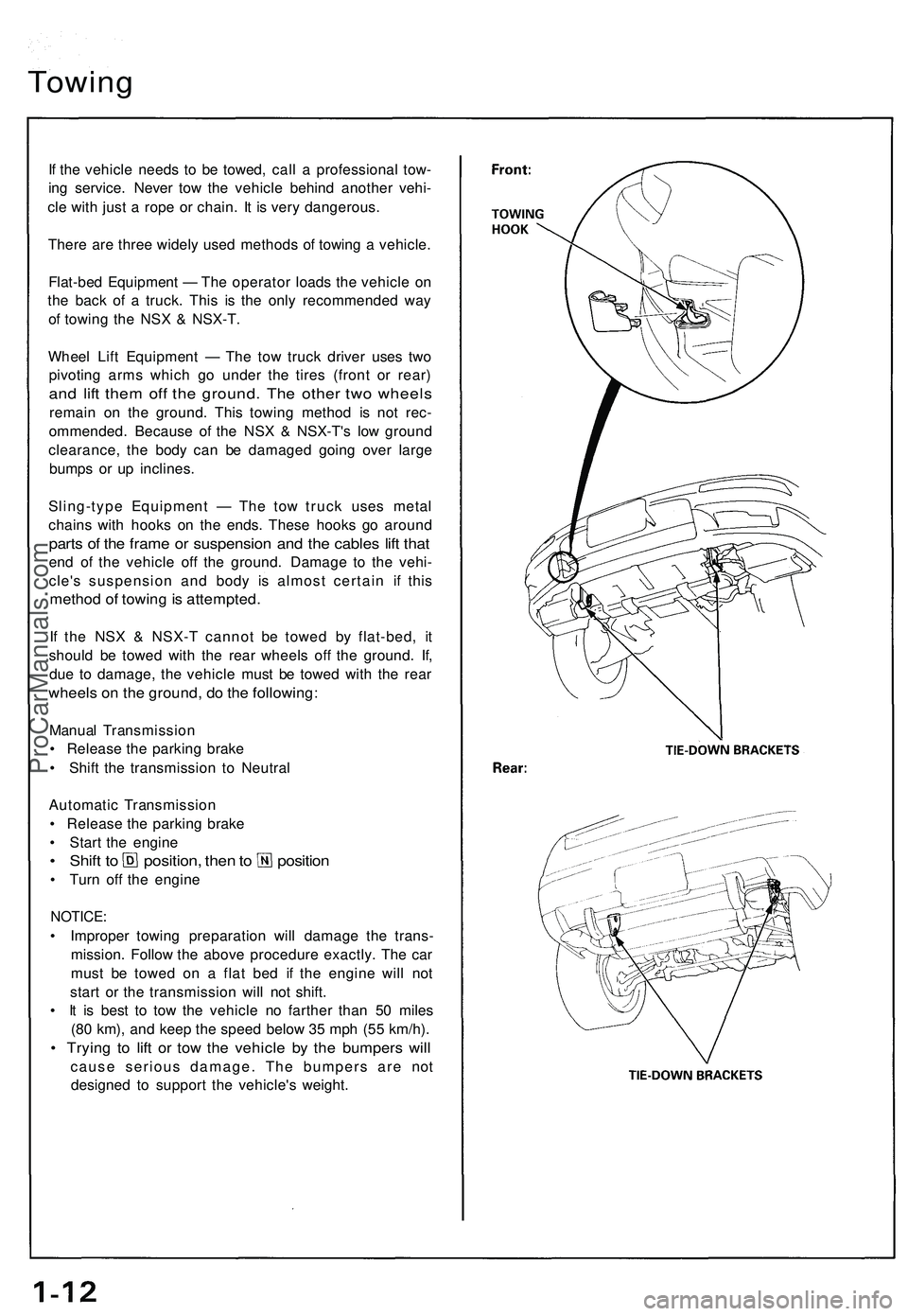
If the vehicle needs to be towed, call a professional tow-
ing service. Never tow the vehicle behind another vehi-
cle with just a rope or chain. It is very dangerous.
There are three widely used methods of towing a vehicle.
Flat-bed Equipment — The operator loads the vehicle on
the back of a truck. This is the only recommended way
of towing the NSX & NSX-T.
Wheel Lift Equipment — The tow truck driver uses two
pivoting arms which go under the tires (front or rear)
and lift them off the ground. The other two wheels
remain on the ground. This towing method is not rec-
ommended. Because of the NSX & NSX-T's low ground
clearance, the body can be damaged going over large
bumps or up inclines.
Sling-type Equipment — The tow truck uses metal
chains with hooks on the ends. These hooks go around
parts of the frame or suspension and the cables lift that
end of the vehicle off the ground. Damage to the vehi-
cle's suspension and body is almost certain if this
method of towing is attempted.
If the NSX & NSX-T cannot be towed by flat-bed, it
should be towed with the rear wheels off the ground. If,
due to damage, the vehicle must be towed with the rear
wheels on the ground, do the following:
Manual Transmission
• Release the parking brake
• Shift the transmission to Neutral
Automatic Transmission
• Release the parking brake
• Start the engine
• Shift to position, then to position
• Turn off the engine
NOTICE:
• Improper towing preparation will damage the trans-
mission. Follow the above procedure exactly. The car
must be towed on a flat bed if the engine will not
start or the transmission will not shift.
• It is best to tow the vehicle no farther than 50 miles
(80 km), and keep the speed below 35 mph (55 km/h).
• Trying to lift or tow the vehicle by the bumpers will
cause serious damage. The bumpers are not
designed to support the vehicle's weight.ProCarManuals.com
Page 407 of 1503
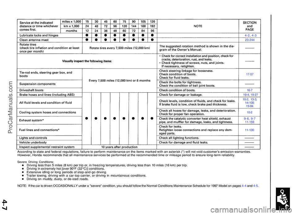
4-2, 4-3
23-244
17-57
16-7
19-4 , 19-2 7
10-2, 13-3 ,14-10 519-84
10-2
9-6, 9-711-15 9
11-130
Accordin g to stat e an d federa l regulations , failur e to perfor m maintenanc e o n th e item s marke d wit h a n asteris k (* ) wil l no t voi d customer' s emissio n warranties .
However , Hond a recommend s tha t al l maintenanc e service s b e performe d a t th e recommende d tim e o r mileag e perio d to ensur e long-ter m reliability .
Severe Drivin g Conditions :Driving les s tha n 5 mile s ( 8 km ) pe r tri p or , i n freezin g temperatures , drivin g les s tha n 1 0 mile s (1 6 km ) pe r trip .
Drivin g in extremel y ho t [ove r 90° F (32°C) ] conditions .
Extensiv e idlin g o r lon g period s o f stop-and-g o driving .
Traile r towing , drivin g wit h a car-to p carrier , o r drivin g in mountainou s conditions .
Drivin g o n muddy , dusty , o r de-ice d roads .
NOTE : I f th e ca r i s drive n OCCASIONALL Y unde r a "severe " condition , yo u shoul d follo w th e Norma l Condition s Maintenanc e Schedul e fo r 199 7 Mode l o n page s 4- 4 an d 4-5 .
ProCarManuals.com
Page 424 of 1503
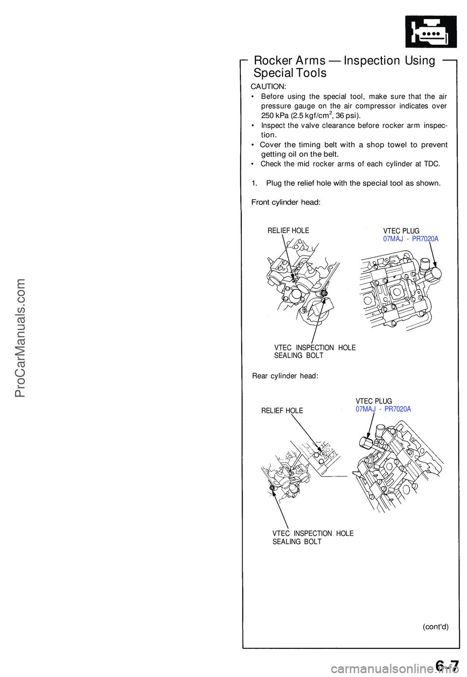
Rocker Arm s — Inspectio n Usin g
Specia l Tool s
CAUTION :
• Befor e usin g th e specia l tool , mak e sur e tha t th e ai r
pressur e gaug e o n th e ai r compresso r indicate s ove r
250 kP a (2. 5 kgf/cm2, 3 6 psi) .
• Inspec t th e valv e clearanc e befor e rocke r ar m inspec -
tion.
• Cove r th e timin g bel t wit h a sho p towe l t o preven t
getting oi l o n th e belt .
• Chec k th e mi d rocke r arm s o f eac h cylinde r a t TDC .
1. Plu g th e relie f hol e wit h th e specia l too l a s shown .
Front cylinde r head :
RELIE F HOL E
VTEC PLU G
07MA J - PR7020 A
VTE C INSPECTIO N HOL E
SEALIN G BOL T
Rear cylinde r head :
RELIE F HOL E VTE
C PLU G
07MA J - PR7020 A
VTE C INSPECTIO N HOL E
SEALIN G BOL T
(cont'd )
ProCarManuals.com
Page 443 of 1503
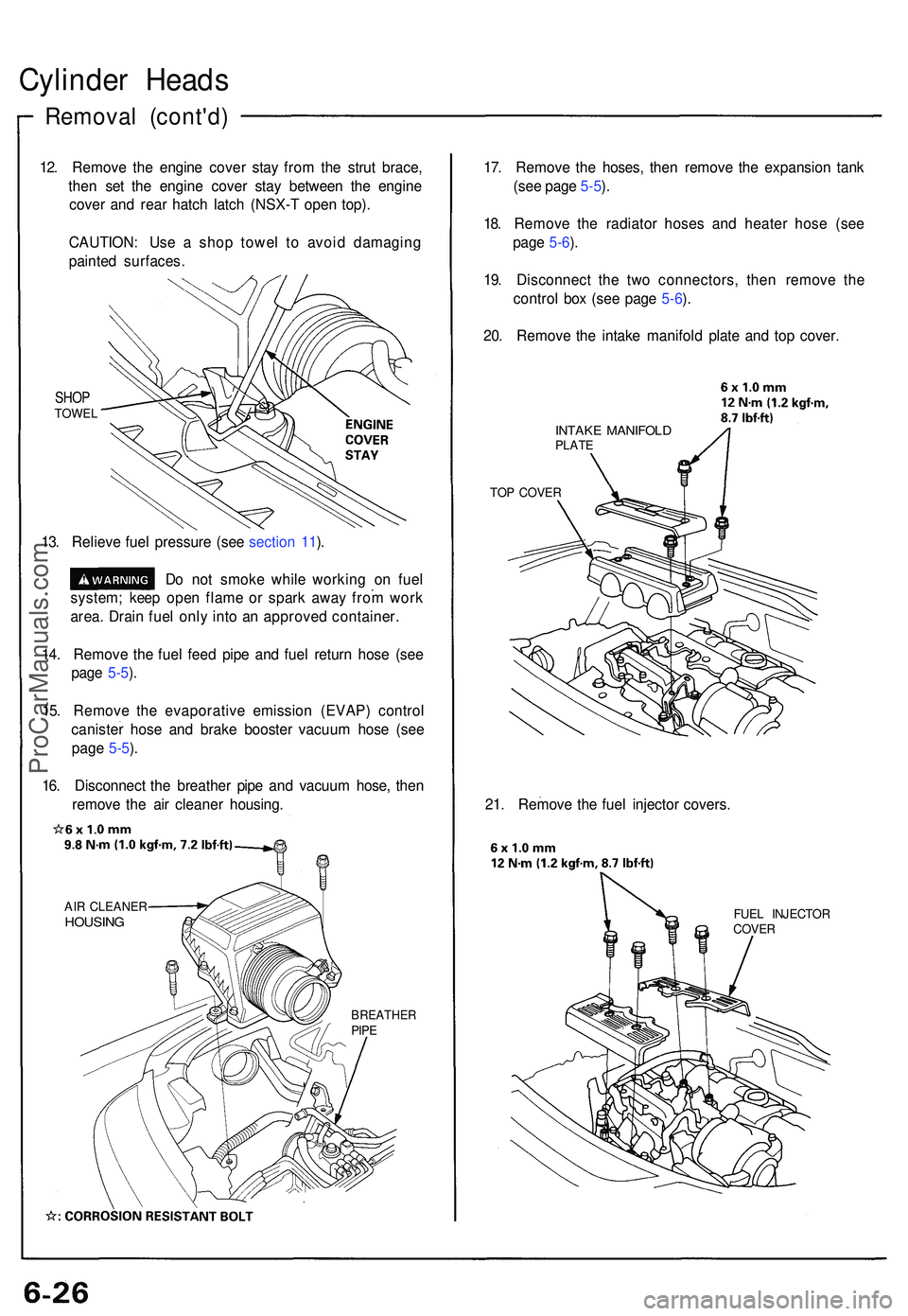
Cylinder Head s
Remova l (cont'd )
12. Remov e th e engin e cove r sta y fro m th e stru t brace ,
the n se t th e engine cover sta y betwee n th e engine
cove r an d rea r hatc h latc h (NSX- T ope n top) .
CAUTION : Us e a sho p towe l t o avoi d damagin g
painte d surfaces .
SHOPTOWE L
13. Reliev e fue l pressur e (se e sectio n 11 ).
D o no t smok e whil e workin g o n fue l
system ; kee p ope n flam e o r spar k awa y fro m wor k
area . Drai n fue l onl y int o a n approve d container .
14 . Remov e th e fue l fee d pip e an d fue l retur n hos e (se e
pag e 5-5 ).
15 . Remov e th e evaporativ e emissio n (EVAP ) contro l
caniste r hos e an d brak e booste r vacuu m hos e (se e
pag e 5-5 ).
16 . Disconnec t th e breathe r pip e an d vacuu m hose , the n
remov e th e ai r cleane r housing .
AIR CLEANE RHOUSING
BREATHE RPIPE
17. Remov e th e hoses , the n remov e th e expansio n tan k
(se e pag e 5-5 ).
18 . Remov e th e radiato r hose s an d heate r hos e (se e
pag e 5-6 ).
19 . Disconnec t th e tw o connectors , the n remov e th e
contro l bo x (se e pag e 5-6 ).
20 . Remov e th e intak e manifol d plat e an d to p cover .
INTAK E MANIFOL DPLATE
TO P COVE R
21. Remov e th e fue l injecto r covers .
FUEL INJECTO R
COVE R
ProCarManuals.com