relay ACURA RL KA9 1996 Service Repair Manual
[x] Cancel search | Manufacturer: ACURA, Model Year: 1996, Model line: RL KA9, Model: ACURA RL KA9 1996Pages: 1954, PDF Size: 61.44 MB
Page 1536 of 1954
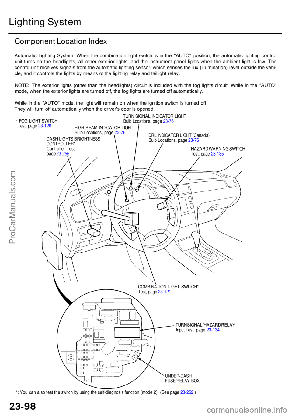
*: Yo u ca n als o tes t th e switc h b y usin g th e self-diagnosi s functio n (mod e 2) . (Se e pag e 23-252 .)
UNDER-DAS HFUSE/RELAY BO X
TUR N SIGNAL/HAZAR D RELA Y
Inpu t Test , pag e 23-13 4
COMBINATIO
N LIGH T SWITCH *
Test , pag e 23-12 1
DAS
H LIGHT S BRIGHTNES S
CONTROLLER *Controller Test ,
pag e 23-25 6
Lightin g Syste m
Componen t Locatio n Inde x
Automati c Lightin g System : Whe n th e combinatio n ligh t switc h i s i n th e "AUTO " position , th e automati c lightin g contro l
uni t turn s o n th e headlights , al l othe r exterio r lights , an d th e instrumen t pane l light s whe n th e ambien t ligh t i s low . Th e
contro l uni t receive s signal s fro m th e automati c lightin g sensor , whic h sense s th e lu x (illumination ) leve l outsid e th e vehi -
cle , an d it control s th e light s b y mean s o f th e lightin g rela y an d tailligh t relay .
NOTE : Th e exterio r light s (othe r tha n th e headlights ) circui t i s include d wit h th e fo g light s circuit . Whil e i n th e "AUTO "
mode , whe n th e exterio r light s ar e turne d off , th e fo g light s ar e turne d of f automatically .
Whil e in th e "AUTO " mode , th e ligh t wil l remai n o n whe n th e ignitio n switc h i s turne d off .
The y wil l tur n of f automaticall y whe n th e driver' s doo r i s opened .
• FO G LIGH T SWITC H
Test , pag e 23-12 6
HIGH BEA M INDICATO R LIGH T
Bul b Locations , pag e 23-7 6
TUR
N SIGNA L INDICATO R LIGH T
Bul b Locations , pag e 23-7 6
DR L INDICATO R LIGH T (Canada )
Bul b Locations , pag e 23-7 6
HAZAR D WARNIN G SWITC H
Test , pag e 23-13 5
ProCarManuals.com
Page 1556 of 1954
Turn Signal/Hazar d Flashe r Syste m
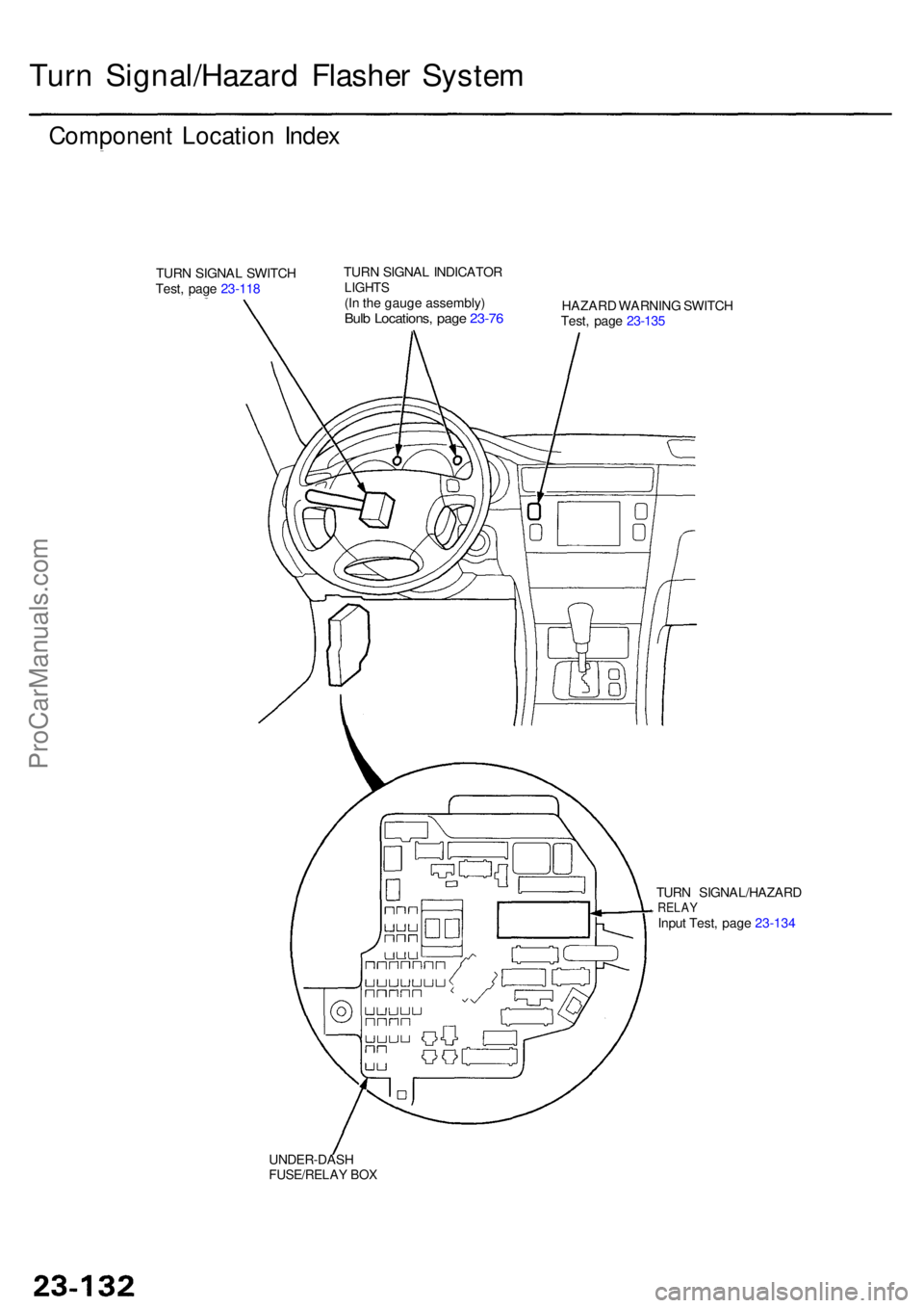
Componen t Locatio n Inde x
TURN SIGNA L SWITC H
Test , pag e 23-11 8 TUR
N SIGNA L INDICATO RLIGHTS(In th e gaug e assembly )Bulb Locations , pag e 23-7 6HAZAR D WARNIN G SWITC H
Test , pag e 23-13 5
TUR N SIGNAL/HAZAR D
RELAYInput Test , pag e 23-13 4
UNDER-DAS H
FUSE/RELAY BO X
ProCarManuals.com
Page 1557 of 1954
Turn Signal/Hazar d Flashe r Syste m
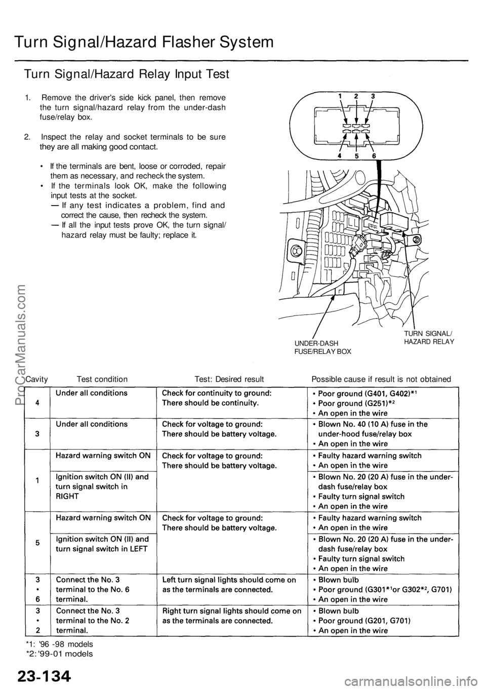
Turn Signal/Hazar d Rela y Inpu t Tes t
1. Remov e th e driver' s sid e kic k panel , the n remov e
th e tur n signal/hazar d rela y fro m th e under-das h
fuse/rela y box .
2 . Inspec t th e rela y an d socke t terminal s t o b e sur e
they ar e al l makin g goo d contact .
• I f th e terminal s ar e bent , loos e o r corroded , repai r
the m as necessary , an d rechec k th e system .
• I f th e terminal s loo k OK , mak e th e followin g
inpu t test s a t th e socket .
If an y tes t indicate s a problem , fin d an d
correc t th e cause , the n rechec k th e system .
I f al l th e inpu t test s prov e OK , th e tur n signal /
hazar d rela y mus t b e faulty ; replac e it .
UNDER-DAS HFUSE/RELAY BO X
TUR N SIGNAL /HAZARD RELA Y
Cavity Tes t conditio n Test : Desire d resul t Possibl e caus e if resul t i s no t obtaine d
*1 : '9 6 -9 8 model s
*2: '99-0 1 model s
ProCarManuals.com
Page 1575 of 1954
Horns
Componen t Locatio n Inde x
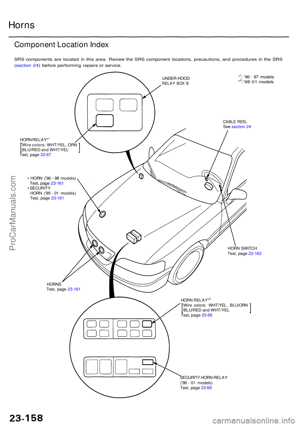
SRS component s ar e locate d i n thi s area . Revie w th e SR S componen t locations , precautions , an d procedure s i n th e SR S
( sectio n 24 ) befor e performin g repair s o r service .
CABLE REE LSee sectio n 2 4
UNDER-HOO
D
RELAY BO X B
Wir e colors : WHT/YEL , OR N
BLU/RE D an d WHT/YE L
Test , pag e 23-6 7
HOR
N RELAY*
1
• HOR N ('9 6 - 9 8 models )Test, pag e 23-161• SECURIT Y
HOR N ('9 9 - 0 1 models )
Test , pag e 23-161
HORN S
Test , pag e 23-161
SECURITY HOR N RELA Y
('9 9 - 0 1 models )
Test , pag e 23-6 8
Wir
e colors : WHT/YEL , BLU/OR N
BLU/RE D an d WHT/YE L
Test , pag e 23-6 9
HOR N RELAY*2
HOR N SWITC H
Test , pag e 23-162
*1: '9 6 - 9 7 model s*2:'98-01 model s
ProCarManuals.com
Page 1579 of 1954
Seat Bel t Tensio n Reduce r
Test
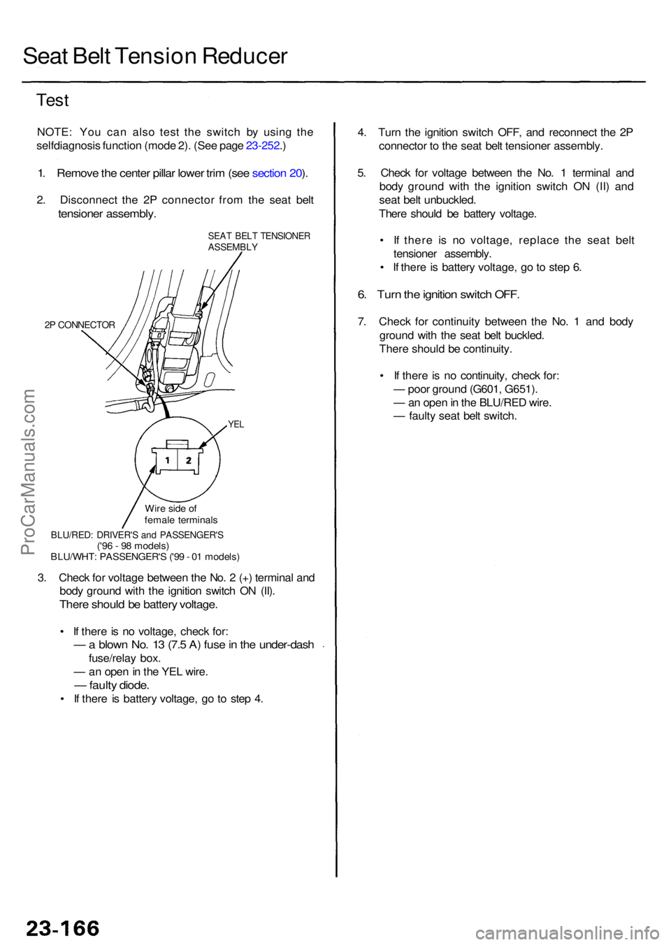
NOTE : Yo u ca n als o tes t th e switc h b y usin g th e
selfdiagnosi s functio n (mod e 2) . (Se e pag e 23-252 .)
1 . Remov e th e cente r pilla r lowe r tri m (se e sectio n 20 ).
2 . Disconnec t th e 2 P connecto r fro m th e sea t bel t
tensione r assembly .
SEAT BEL T TENSIONE RASSEMBLY
2P CONNECTO R
YEL
4. Tur n th e ignitio n switc h OFF , an d reconnec t th e 2 P
connecto r t o th e sea t bel t tensione r assembly .
5 . Chec k fo r voltag e betwee n th e No . 1 termina l an d
bod y groun d wit h th e ignitio n switc h O N (II ) an d
sea t bel t unbuckled .
Ther e shoul d b e batter y voltage .
• I f ther e i s n o voltage , replac e th e sea t bel t
tensione r assembly .
• I f ther e is batter y voltage , g o to ste p 6 .
6. Tur n th e ignitio n switc h OFF .
7. Chec k fo r continuit y betwee n th e No . 1 an d bod y
groun d wit h th e sea t bel t buckled .
Ther e shoul d b e continuity .
• I f ther e is n o continuity , chec k for :
— poo r groun d (G601 , G651) .
— an ope n in th e BLU/RE D wire .
— fault y sea t bel t switch .
3 . Chec k fo r voltag e betwee n th e No . 2 (+ ) termina l an d
bod y groun d wit h th e ignitio n switc h O N (II) .
Ther e shoul d b e batter y voltage .
• I f ther e is n o voltage , chec k for :
— a blow n No . 1 3 (7. 5 A ) fus e in th e under-das h
fuse/relay box .
— an ope n in th e YE L wire .
— fault y diode .
• I f ther e i s batter y voltage , g o t o ste p 4 .
BLU/RED : DRIVER' S an d PASSENGER' S('96 - 9 8 models )
BLU/WHT : PASSENGER' S ('9 9 - 0 1 models )
Wir
e sid e o f
femal e terminal s
ProCarManuals.com
Page 1586 of 1954
Description
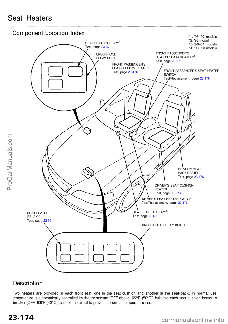
Two heater s ar e provide d i n eac h fron t seat ; on e i n th e sea t cushio n an d anothe r i n th e seat-back . I n norma l use ,
temperatur e i s automaticall y controlle d b y th e thermosta t [OF F abov e 122° F (50°C) ] buil t int o eac h sea t cushio n heater . A
breake r [OF F 109° F (43°C) ] cut s of f th e circui t t o preven t abnorma l temperatur e rise .
SEA T HEATE RRELAY*2
Test, pag e 23-6 9
UNDER-HOOD RELA Y BO X C
SEA
T HEATE R RELAY*
3
Test , pag e 23-67
DRIVER'
S SEA T HEATE R SWITC H
Test/Replacement , pag e 23-17 6
DRIVER'
S SEA T CUSHIO N
HEATERTest, pag e 23-17 6
DRIVER'
S SEA T
BAC K HEATE R
Test , pag e 23-17 6
FRON
T PASSENGER' S SEA T HEATE R
SWITCHTest/Replacement , pag e 23-17 6
FRON
T PASSENGER' S
SEAT CUSHIO N HEATER*4
Test , pag e 23-17 6
FRON T PASSENGER' S
SEA T CUSHIO N HEATE R
Test , pag e 23-17 6
UNDER-HOO
D
RELA Y BO X B
SEA
T HEATE R RELAY*
1
Test , pag e 23-67
*1 : '9 6 -9 7 model s*2: '9 8 mode l*3:'99-0 1 model s*4: '9 6 - 9 8 model s
Componen t Locatio n Inde x
Seat Heater s
ProCarManuals.com
Page 1589 of 1954
Automatic Insid e Dimmin g Mirro r
Test/Replacemen t
NOTE: Befor e testing , chec k th e No . 1 3 (7. 5 A ) fuse .
1 . Remov e th e fron t ceilin g ligh t (se e pag e 23-262 ).
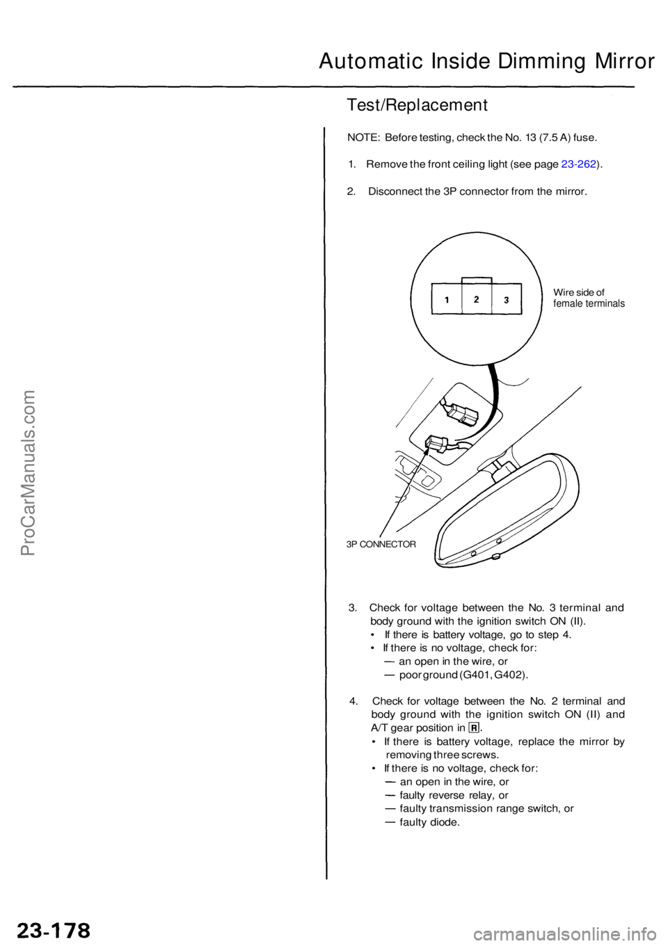
2 . Disconnec t th e 3 P connecto r fro m th e mirror .
Wire sid e o ffemal e terminal s
3P CONNECTO R
3. Chec k fo r voltag e betwee n th e No . 3 termina l an d
bod y groun d wit h th e ignitio n switc h O N (II) .
• I f ther e is batter y voltage , g o t o ste p 4 .
• I f ther e is n o voltage , chec k for :
a n ope n in th e wire , o r
poo r groun d (G401 , G402) .
4 . Chec k fo r voltag e betwee n th e No . 2 termina l an d
bod y groun d wit h th e ignitio n switc h O N (II ) an d
A/T gea r positio n in
• I f ther e i s batter y voltage , replac e th e mirro r b y
removin g thre e screws .
• I f ther e is n o voltage , chec k for :
a n ope n in th e wire , o r
fault y revers e relay , o r
fault y transmissio n rang e switch , o r
fault y diode .
ProCarManuals.com
Page 1592 of 1954
Immobilizer Syste m
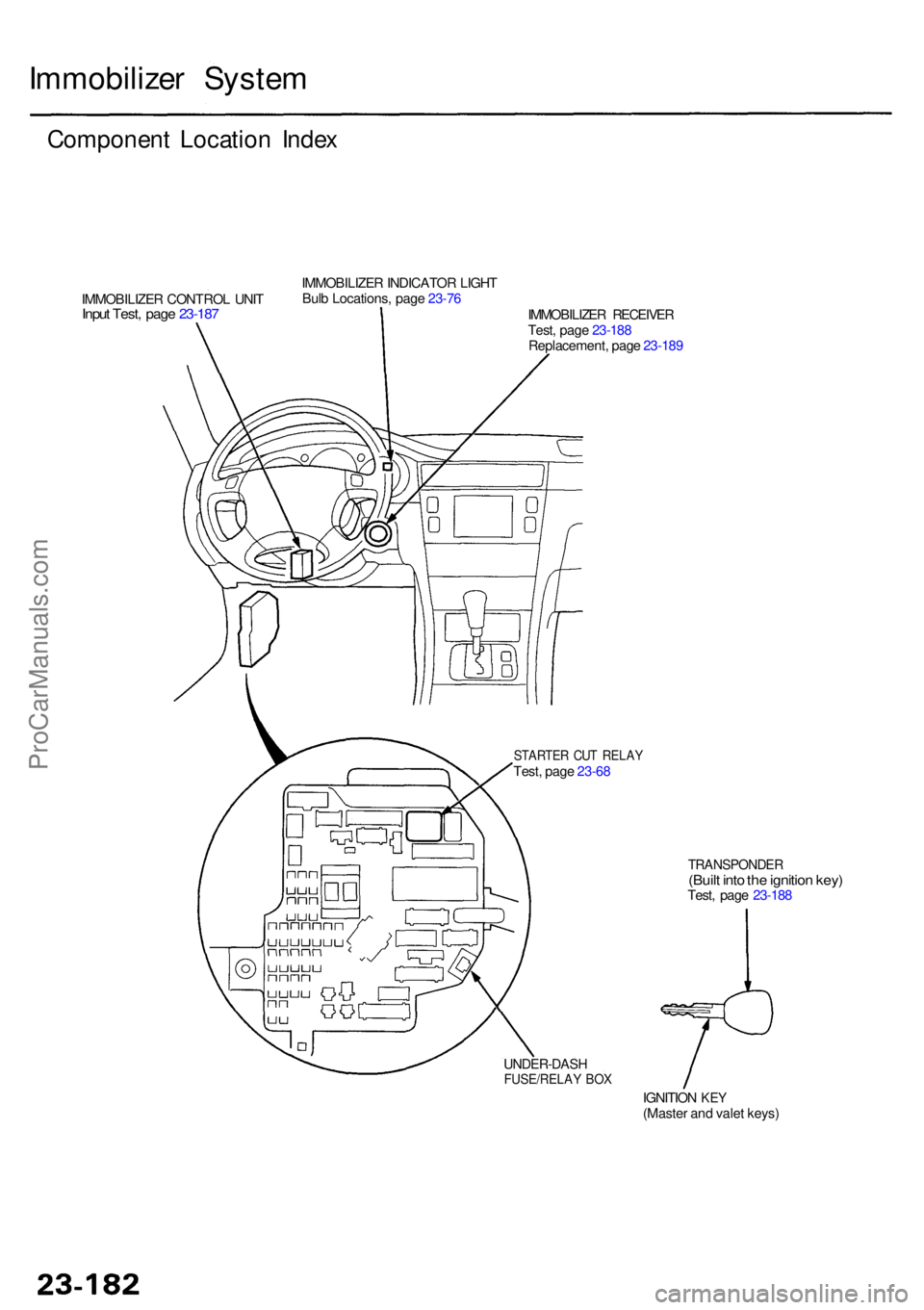
Componen t Locatio n Inde x
IMMOBILIZE R CONTRO L UNI TInput Test , pag e 23-18 7
IMMOBILIZE R INDICATO R LIGH T
Bul b Locations , pag e 23-76
IMMOBILIZER RECEIVE R
Test , pag e 23-18 8
Replacement , pag e 23-18 9
STARTE R CU T RELA YTest, pag e 23-6 8
TRANSPONDE R(Built int o th e ignitio n key )Test , pag e 23-18 8
IGNITIO N
KEY(Maste r an d vale t keys )
UNDER-DAS HFUSE/RELAY BO X
ProCarManuals.com
Page 1593 of 1954
Description
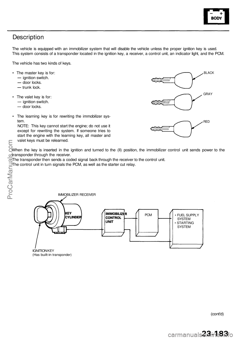
The vehicl e is equippe d wit h a n immobilize r syste m tha t wil l disabl e th e vehicl e unles s th e prope r ignitio n ke y i s used .
Thi s syste m consist s o f a transponde r locate d in th e ignitio n key , a receiver , a contro l unit , a n indicato r light , an d th e PCM .
Th e vehicl e ha s tw o kind s o f keys .
• Th e maste r ke y i s for :
ignitio n switch .
door locks .
trunk lock .
• Th e vale t ke y i s for :
ignitio n switch .
door locks .
• Th e learnin g ke y i s fo r rewritin g th e immobilize r sys -
tem.
NOTE : Thi s ke y canno t star t th e engine ; d o no t us e it
excep t fo r rewritin g th e system . I f someon e trie s t o
star t th e engin e wit h th e learnin g key , al l maste r an d
vale t key s mus t b e relearned .
Whe n th e ke y i s inserte d i n th e ignitio n an d turne d t o th e (II ) position , th e immobilize r contro l uni t send s powe r t o th e
transponde r throug h th e receiver .
Th e transponde r the n send s a code d signa l bac k throug h th e receive r t o th e contro l unit .
Th e contro l uni t i n tur n signal s th e PCM , a s wel l a s th e starte r cu t relay .
IMMOBILIZE R RECEIVE R
IGNITION KEY(Ha s built-i n transponder ) •
FUE L SUPPL Y
SYSTE M
• STARTIN G
SYSTEM
PCM
BLAC K
GRAY
RED
(cont'd )
ProCarManuals.com
Page 1666 of 1954
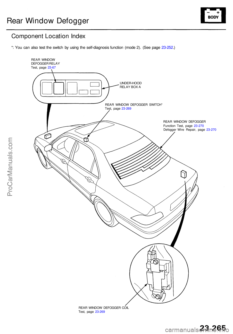
REAR WINDO W DEFOGGE R COI L
Test , pag e 23-26 9
Rear Windo w Defogge r
Componen t Locatio n Inde x
*: Yo u ca n als o tes t th e switc h b y usin g th e self-diagnosi s functio n (mod e 2) . (Se e pag e 23-252 .)
REA R WINDO W
DEFOGGE R RELA Y
Test , pag e 23-6 7
UNDER-HOO DRELAY BO X A
REA R WINDO W DEFOGGE R SWITCH *
Test , pag e 23-26 9
REAR WINDO W DEFOGGE R
Functio n Test , pag e 23-27 0
Defogge r Wir e Repair , pag e 23-27 0
ProCarManuals.com