engine ACURA RL KA9 1996 Service Repair Manual
[x] Cancel search | Manufacturer: ACURA, Model Year: 1996, Model line: RL KA9, Model: ACURA RL KA9 1996Pages: 1954, PDF Size: 61.44 MB
Page 590 of 1954
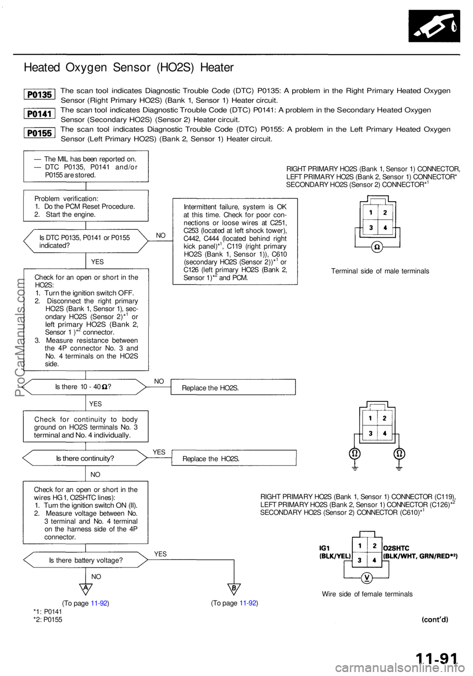
Heated Oxyge n Senso r (HO2S ) Heate r
The sca n too l indicate s Diagnosti c Troubl e Cod e (DTC ) P0135 : A proble m in th e Righ t Primar y Heate d Oxyge n
Sensor (Righ t Primar y HO2S ) (Ban k 1 , Senso r 1 ) Heate r circuit .
The sca n too l indicate s Diagnosti c Troubl e Cod e (DTC ) P0141 : A proble m in th e Secondar y Heate d Oxyge n
Sensor (Secondar y HO2S ) (Senso r 2 ) Heate r circuit .
The sca n too l indicate s Diagnosti c Troubl e Cod e (DTC ) P0155 : A proble m in th e Lef t Primar y Heate d Oxyge n
Sensor (Lef t Primar y HO2S ) (Ban k 2 , Senso r 1 ) Heate r circuit .
— Th e MI L ha s bee n reporte d on .
— DT C P0135 , P014 1 and/o r
P015 5 ar e stored .
Proble m verification :
1 . D o th e PC M Rese t Procedure .
2 . Star t th e engine .
I s DT C P0135 , P014 1 o r P015 5
indicated ?
YES
Chec k fo r a n ope n o r shor t i n th eHO2S :1. Tur n th e ignitio n switc h OFF .2. Disconnec t th e righ t primar y
HO2 S (Ban k 1 , Senso r 1) , sec -
ondar y HO2 S (Senso r 2)*
1 o rleft primar y HO2 S (Ban k 2 ,Senso r 1 )*2 connector .
3 . Measur e resistanc e betwee n
th e 4 P connecto r No . 3 an d
No . 4 terminal s o n th e HO2 S
side .
Is there 10 - 40 ?
YE S
Chec k fo r continuit y t o bod y
groun d o n HO2 S terminal s No . 3
termina l an d No . 4 individually .
Is ther e continuity ?
NO
Chec k fo r a n ope n o r shor t i n th e
wire s H G 1, O2SHT C lines) :
1. Tur n th e ignitio n switc h O N (II) .2. Measur e voltag e betwee n No .
3 termina l an d No . 4 termina l
o n th e harnes s sid e o f th e 4 P
connector . RIGH
T PRIMAR Y HO2 S (Ban k 1 , Senso r 1 ) CONNECTOR ,
LEF T PRIMAR Y HO2 S (Ban k 2 , Senso r 1 ) CONNECTOR *
SECONDAR Y HO2 S (Senso r 2 ) CONNECTOR*
1
N O
Intermitten t failure , syste m is O K
a t thi s time . Chec k fo r poo r con -
nection s o r loos e wire s a t C251 ,
C25 3 (locate d a t lef t shoc k tower) ,
C442 , C44 4 (locate d behin d righ t
kic k panel)*
1, C11 9 (righ t primar y
HO2 S (Ban k 1 , Senso r 1)) , C61 0
(secondar y HO2 S (Senso r 2))*
1 o r
C12 6 (lef t primar y HO2 S (Ban k 2 ,
Senso r 1)*
2 an d PCM . Termina
l sid e o f mal e terminal s
Replac e th e HO2S .
Replac e th e HO2S .
RIGHT PRIMAR Y HO2 S (Ban k 1 , Senso r 1 ) CONNECTO R (C119) ,
LEF T PRIMAR Y HO2 S (Ban k 2 , Senso r 1 ) CONNECTO R (C126)*
2
SECONDAR Y HO2 S (Senso r 2 ) CONNECTO R (C610)*1
Is ther e batter y voltage ?YES
NO
(T o pag e 11-92 ) (T
o pag e 11-92 ) Wir
e sid e o f femal e terminal s*1: P014 1*2: P015 5
YES
NO
ProCarManuals.com
Page 593 of 1954
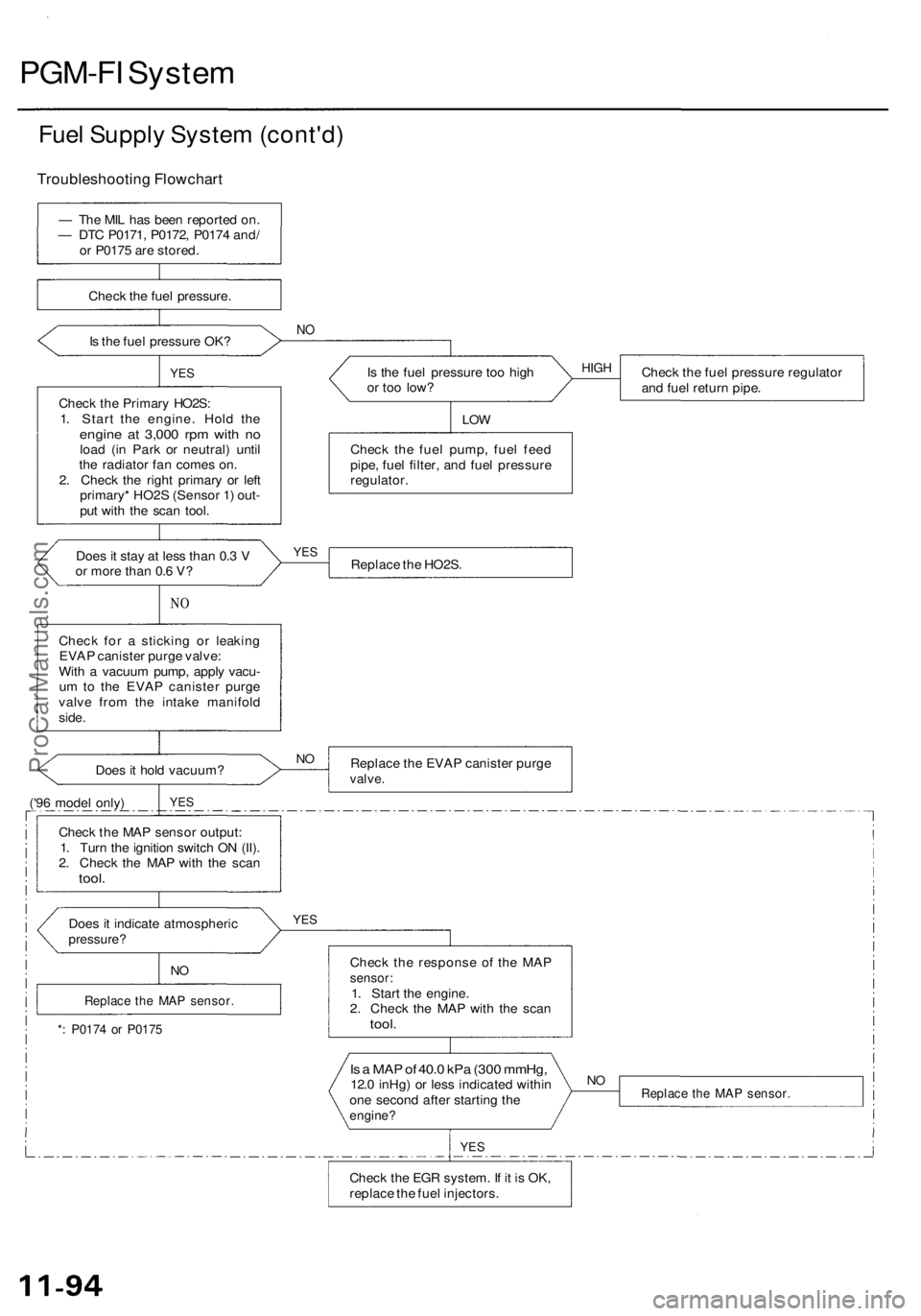
PGM-FI System
Fuel Supply System (cont'd)
— The MIL has been reported on.
— DTC P0171, P0172, P0174 and/
or P0175 are stored.
Check the fuel pressure.
Is the fuel pressure OK?
NO
YES
Check the Primary HO2S:
1. Start the engine. Hold the
engine at 3,000 rpm with no
load (in Park or neutral) until
the radiator fan comes on.
2. Check the right primary or left
primary* HO2S (Sensor 1) out-
put with the scan tool.
Is the fuel pressure too high
or too low?
Check the fuel pressure regulator
and fuel return pipe.
LOW
Check the fuel pump, fuel feed
pipe, fuel filter, and fuel pressure
regulator.
Does it stay at less than 0.3 V
or more than 0.6 V?
Replace the HO2S.
NO
Check for a sticking or leaking
EVAP canister purge valve:
With a vacuum pump, apply vacu-
um to the EVAP canister purge
valve from the intake manifold
side.
Does it hold vacuum?
('96 model only)
Replace the EVAP canister purge
valve.
YES
Check the MAP sensor output:
1. Turn the ignition switch ON (II).
2. Check the MAP with the scan
tool.
Does it indicate atmospheric
pressure?
YES
*: P0174 or P0175
Check the response of the MAP
sensor:
1. Start the engine.
2. Check the MAP with the scan
tool.
Is a MAP of 40.0 kPa (300 mmHg,
12.0 inHg) or less indicated within
one second after starting the
engine?
Replace the MAP sensor.
YES
Check the EGR system. If it is OK,
replace the fuel injectors.
NO
NO
Replace the MAP sensor.
NO
YES
HIGH
Troubleshooting FlowchartProCarManuals.com
Page 594 of 1954
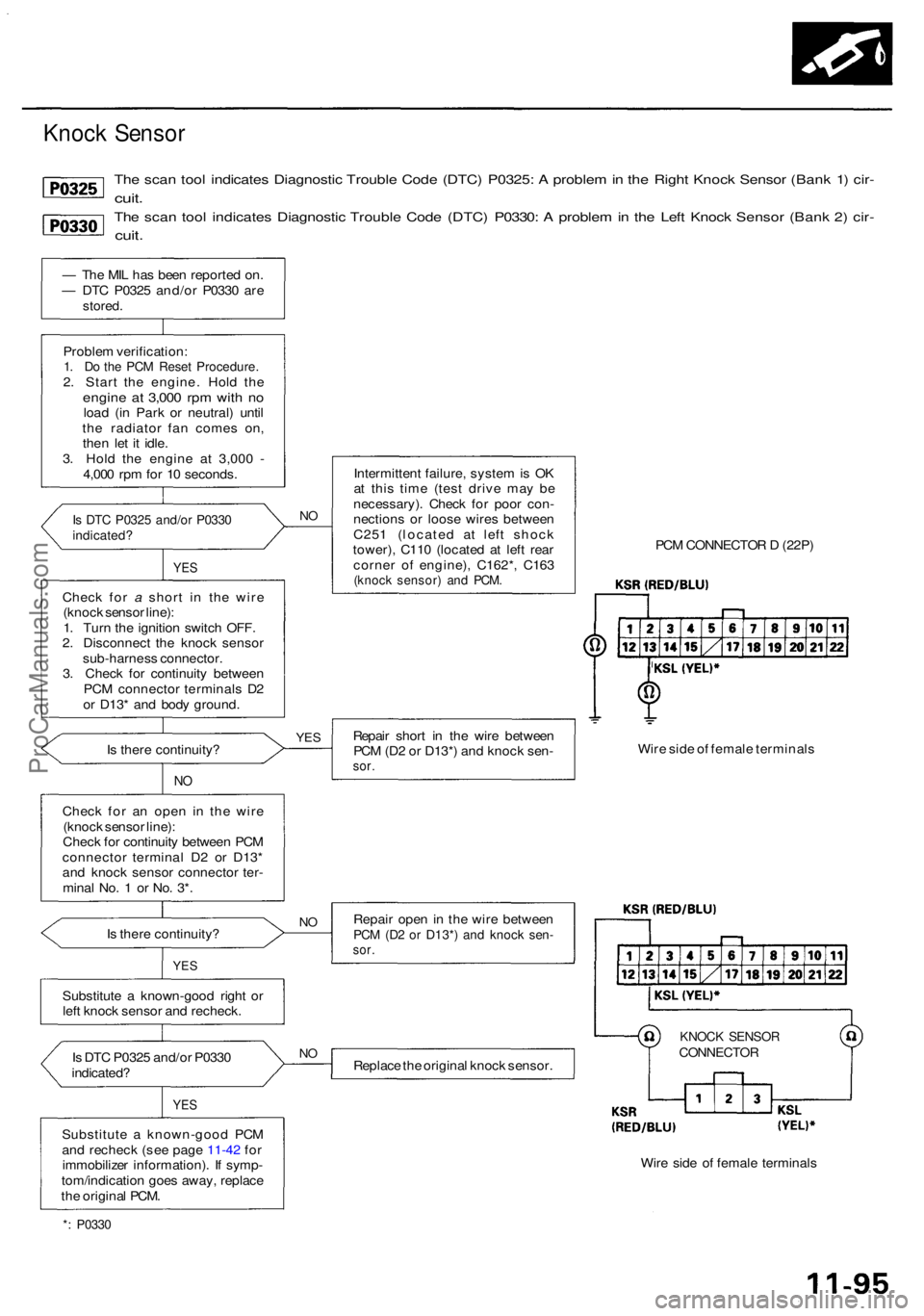
The sca n too l indicate s Diagnosti c Troubl e Cod e (DTC ) P0325 : A proble m in th e Righ t Knoc k Senso r (Ban k 1 ) cir -
cuit .
The sca n too l indicate s Diagnosti c Troubl e Cod e (DTC ) P0330 : A proble m in th e Lef t Knoc k Senso r (Ban k 2 ) cir -
cuit .
— Th e MI L ha s bee n reporte d on .
— DT C P032 5 and/o r P033 0 ar e
stored .
Proble m verification :1. D o th e PC M Rese t Procedure .2. Star t th e engine . Hol d th eengin e a t 3,00 0 rp m wit h n oloa d (i n Par k o r neutral ) unti l
th e radiato r fa n come s on ,
the n le t i t idle .
3 . Hol d th e engin e a t 3,00 0 -
4,00 0 rp m fo r 1 0 seconds .
Is DT C P032 5 and/o r P033 0indicated ?
YES
Chec k fo r a shor t i n th e wir e
(knoc k senso r line) :
1 . Tur n th e ignitio n switc h OFF .
2 . Disconnec t th e knoc k senso r
sub-harnes s connector .
3 . Chec k fo r continuit y betwee n
PC M connecto r terminal s D 2
o r D13 * an d bod y ground .
I s ther e continuity ?
NO
Chec k fo r a n ope n i n th e wir e
(knoc k senso r line) :
Chec k fo r continuit y betwee n PC M
connecto r termina l D 2 o r D13 *
an d knoc k senso r connecto r ter -
mina l No . 1 o r No . 3* .
I s ther e continuity ?
YES
Substitut e a known-goo d righ t o r
lef t knoc k senso r an d recheck .
I s DT C P032 5 and/o r P033 0
indicated ?
YES
Substitut e a known-goo d PC M
an d rechec k (se e pag e 11-42 fo r
immobilize r information) . I f symp -
tom/indicatio n goe s away , replac e
th e origina l PCM .
NO
Intermitten t failure , syste m is O K
a t thi s tim e (tes t driv e ma y b e
necessary) . Chec k fo r poo r con -
nection s o r loos e wire s betwee n
C25 1 (locate d a t lef t shoc k
tower) , C11 0 (locate d a t lef t rea r
corne r o f engine) , C162* , C16 3
(knoc k sensor ) an d PCM .
PCM CONNECTO R D (22P )
Repai r shor t i n th e wir e betwee n
PC M (D 2 o r D13* ) an d knoc k sen -
sor.
Wir e sid e o f femal e terminal s
Repai r ope n in th e wir e betwee n
PCM (D 2 o r D13* ) an d knoc k sen -sor.
KNOC K SENSO RCONNECTO RReplace th e origina l knoc k sensor .
Wire sid e o f femal e terminal s
*: P033 0
NO
N
O
YE S
Knoc k Senso r
ProCarManuals.com
Page 600 of 1954
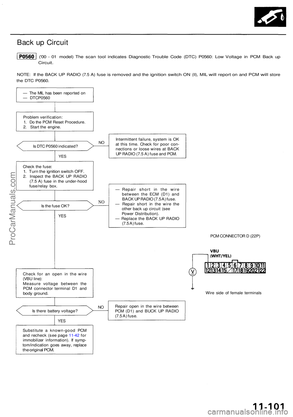
Back u p Circui t
('00 - 0 1 model ) Th e sca n too l indicate s Diagnosti c Troubl e Cod e (DTC ) P0560 : Lo w Voltag e i n PC M Bac k u p
Circuit .
NOTE: If th e BAC K UP RADI O (7.5 A) fus e is remove d and th e ignitio n switch ON (II) , MIL will repor t on an d PC M will stor e
the DT C P0560 .
— Th e MI L ha s bee n reporte d o n
— DTCP056 0
Proble m verification :
1 . D o th e PC M Rese t Procedure .
2 . Star t th e engine .
I s DT C P056 0 indicated ?
YES
Intermitten t failure , syste m is O K
a t thi s time . Chec k fo r poo r con -
nection s o r loos e wire s a t BAC K
U P RADI O (7. 5 A ) fus e an d PCM .
Chec k th e fuse :
1. Tur n th e ignitio n switc h OFF .2. Inspect the BAC K U P RADI O
(7. 5 A ) fus e i n th e under-hoo d
fuse/rela y box .
I s th e fus e OK ?
NO
YE S
— Repai r shor t i n th e wir e
betwee n th e EC M (D1 ) an d
BAC K U P RADI O (7. 5 A ) fuse .
— Repai r shor t i n th e wir e th e
othe r bac k u p circui t (se e
Powe r Distribution) .
— Replac e th e BAC K U P RADI O
(7. 5 A ) fuse .
PCM CONNECTO R D (22P )
Chec k fo r a n ope n i n th e wir e
(VB U line) :
Measur e voltag e betwee n th e
PC M connecto r termina l D 1 an d
body ground .Wire sid e o f femal e terminal s
I s ther e batter y voltage ?
YES
Repai r ope n i n th e wir e betwee n
PC M (D1 ) an d BUC K U P RADI O
(7. 5 A ) fuse .
Substitut e a known-goo d PC M
an d rechec k ( se e pag e 11-42 fo r
immobilize r information) . I f symp -
tom/indicatio n goe s away , replac e
the origina l PCM .
NO
NO
ProCarManuals.com
Page 601 of 1954
PGM-FI Syste m
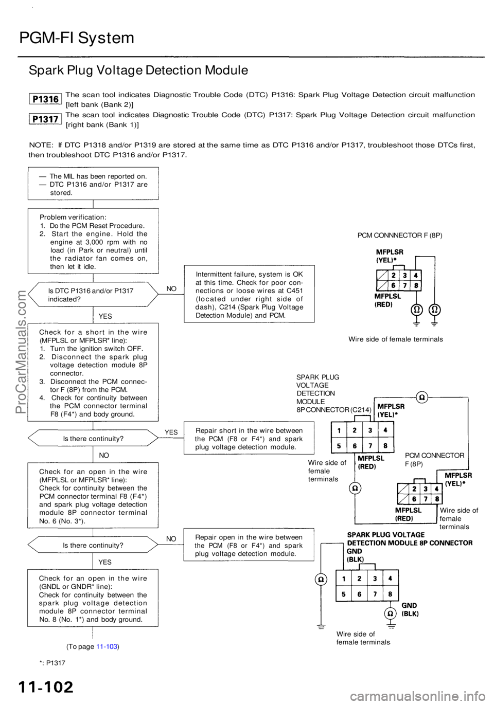
Spark Plu g Voltag e Detectio n Modul e
The sca n too l indicate s Diagnosti c Troubl e Cod e (DTC ) P1316 : Spar k Plu g Voltag e Detectio n circui t malfunctio n
[left ban k (Ban k 2) ]
The sca n too l indicate s Diagnosti c Troubl e Cod e (DTC ) P1317 : Spar k Plu g Voltag e Detectio n circui t malfunctio n
[right ban k (Ban k 1) ]
NOTE : I f DT C P131 8 and/o r P131 9 ar e store d a t th e sam e tim e a s DT C P131 6 and/o r P1317 , troubleshoo t thos e DTC s first ,
then troubleshoo t DT C P131 6 and/o r P1317 .
— Th e MI L ha s bee n reporte d on .
— DT C P131 6 and/o r P131 7 ar e
stored .
Proble m verification :
1 . D o th e PC M Rese t Procedure .
2 . Star t th e engine . Hol d th e
engin e a t 3,00 0 rp m wit h n o
loa d (i n Par k o r neutral ) unti l
th e radiato r fa n come s on ,
the n le t i t idle .
I s DT C P131 6 and/o r P131 7
indicated ?
YES
Chec k fo r a shor t i n th e wir e
(MFPLS L o r MFPLSR * line) :
1 . Tur n th e ignitio n switc h OFF .
2 . Disconnec t th e spar k plu g
voltag e detectio n modul e 8 P
connector .
3 . Disconnec t th e PC M connec -
to r F (8P ) fro m th e PCM .
4 . Chec k fo r continuit y betwee n
th e PC M connecto r termina l
F 8 (F4* ) an d bod y ground .
I s ther e continuity ?
NO
Chec k fo r a n ope n i n th e wir e
(MFPLS L o r MFPLSR * line) :
Chec k fo r continuit y betwee n th e
PC M connecto r termina l F 8 (F4* )
an d spar k plu g voltag e detectio n
modul e 8 P connecto r termina l
No. 6 (No . 3*) .
Is ther e continuity ?
YES
Chec k fo r a n ope n i n th e wir e
(GND L o r GNDR * line) :
Chec k fo r continuit y betwee n th e
spar k plu g voltag e detectio n
modul e 8 P connecto r termina l
No . 8 (No . 1* ) an d bod y ground .
(T o pag e 11-103 ) PC
M CONNNECTO R F (8P )
NO
Intermitten t failure , syste m is O K
a t thi s time . Chec k fo r poo r con -
nection s o r loos e wire s a t C45 1
(locate d unde r righ t sid e o f
dash) , C21 4 (Spar k Plu g Voltag e
Detectio n Module ) an d PCM .
Wire sid e o f femal e terminal s
SPARK PLU GVOLTAG EDETECTIO NMODULE
8 P CONNECTO R (C214 )
Repai r shor t i n th e wir e betwee n
the PC M (F 8 o r F4* ) an d spar kplug voltag e detectio n module .
Wire sid e o f
femal e
terminal s
Repai r ope n in th e wir e betwee n
the PC M (F 8 o r F4* ) an d spar kplug voltag e detectio n module .
Wire sid e o f
femal e terminal s
*: P131 7
Wire sid e o f
femal e
terminal s
NO
PC M CONNECTO RF (8P)
YES
ProCarManuals.com
Page 603 of 1954
![ACURA RL KA9 1996 Service Repair Manual PGM-FI Syste m
The sca n too l indicate s Diagnosti c Troubl e Cod e (DTC ) P1318 : Spar k Plu g Voltag e Detectio n Modul e Rese t circui t
malfunctio n [lef t ban k (Ban k 2) ]
The sca n too l indic ACURA RL KA9 1996 Service Repair Manual PGM-FI Syste m
The sca n too l indicate s Diagnosti c Troubl e Cod e (DTC ) P1318 : Spar k Plu g Voltag e Detectio n Modul e Rese t circui t
malfunctio n [lef t ban k (Ban k 2) ]
The sca n too l indic](/img/32/56992/w960_56992-602.png)
PGM-FI Syste m
The sca n too l indicate s Diagnosti c Troubl e Cod e (DTC ) P1318 : Spar k Plu g Voltag e Detectio n Modul e Rese t circui t
malfunctio n [lef t ban k (Ban k 2) ]
The sca n too l indicate s Diagnosti c Troubl e Cod e (DTC ) P1319 : Spar k Plu g Voltag e Detectio n Modul e Rese t circui t
malfunctio n [righ t ban k (Ban k 1) ]
— Th e MI L ha s bee n reporte d on .
— DT C P131 8 and/o r P131 9 i s
stored .
Proble m verification :
1 . D o th e PC M Rese t Procedure .
2 . Star t th e engine . Hol d th e
engin e a t 3,00 0 rp m wit h n o
loa d (i n Par k o r neutral ) unti l
th e radiato r fa n come s on ,
the n le t i t idle .
I s DT C P131 8 and/o r P131 9
indicated ?
YES
Chec k fo r a shor t i n th e wir e
(PHRST L o r PHRSTR * line) :
1. Tur n th e ignitio n switc h OFF .2. Disconnec t th e spar k plu g
voltag e detectio n modul e 8 P
connector .3. Disconnec t th e PC M connec -tor F (8P) .4. Chec k fo r continuit y betwee n
th e PC M connecto r termina l
F 7 (F3* ) an d bod y ground .
I s ther e continuity ?
NO
Chec k fo r a n ope n i n th e wir e
(PHRST L o r PHRSTR * line) :
Chec k fo r continuit y betwee n th e
PC M connecto r termina l F 7 (F3* )
an d spar k plu g voltag e detectio n
modul e 8 P connecto r termina l
No. 7 (No . 2*) .
Is ther e continuity ?
YES
Chec k fo r a n ope n i n th e wir e
(IG1 L o r lG1R * line) :
1. Tur n th e ignitio n switc h O N (II) .2. Measur e voltag e betwee n th e
spar k plu g voltag e detectio n
modul e 8 P connecto r termina l
No . 5 (No . 4* ) an d bod y ground .
(T o pag e 11-105 )
NO
Intermitten t failure , syste m is O K
a t thi s time . Chec k fo r poo r con -
nection s o r loos e wire s a t C45 1
(locate d unde r righ t sid e o f
dash) , C21 4 (Spar k Plu g Voltag e
Detectio n Module ) an d PCM .
Wire sid e o f femal e terminal s
SPARK PLU GVOLTAG EDETECTIO NMODULE
8 P CONNECTO R (C214 )
Repai r shor t i n th e wir e betwee n
th e PC M (F 7 o r F3* ) an d spar k
plu g voltag e detectio n module .
Wire sid e o f
femal e
terminal s PC
M CONNECTO R
F (8P)
Repai r ope n in th e wir e betwee n
th e PC M (F 7 o r F3* ) an d spar k
plu g voltag e detectio n module . Wir
e sid e o f
femal e
terminal s
*: P131 9
YES
NO
Spar k Plu g Voltag e Detectio n Modul e (cont'd )
PCM CONNECTO R F (8P )
SPAR K PLU G VOLTAG EDETECTIO N MODUL E
8 P CONNECTO R
(C214)
ProCarManuals.com
Page 605 of 1954
PGM-FI Syste m
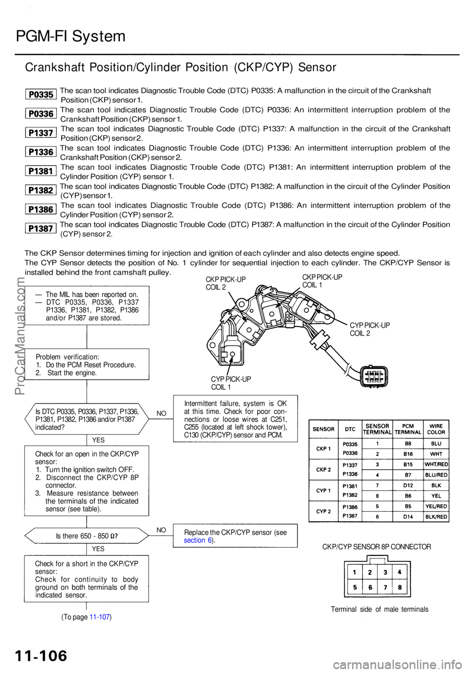
Crankshaf t Position/Cylinde r Positio n (CKP/CYP ) Senso r
The sca n too l indicate s Diagnosti c Troubl e Cod e (DTC ) P0335 : A malfunctio n in th e circui t o f th e Crankshaf t
Positio n (CKP ) senso r 1 .
Th e sca n too l indicate s Diagnosti c Troubl e Cod e (DTC ) P0336 : A n intermitten t interruptio n proble m of the
Crankshaf t Positio n (CKP ) senso r 1 .
Th e sca n too l indicate s Diagnosti c Troubl e Cod e (DTC ) P1337 : A malfunctio n i n th e circui t o f th e Crankshaf t
Positio n (CKP ) senso r 2 .
Th e sca n too l indicate s Diagnosti c Troubl e Cod e (DTC ) P1336 : A n intermitten t interruptio n proble m o f th e
Crankshaf t Positio n (CKP ) senso r 2 .
Th e sca n too l indicate s Diagnosti c Troubl e Cod e (DTC ) P1381 : A n intermitten t interruptio n proble m o f th e
Cylinde r Positio n (CYP ) senso r 1 .
Th e sca n too l indicate s Diagnosti c Troubl e Cod e (DTC ) P1382 : A malfunctio n in th e circui t o f th e Cylinde r Positio r
(CYP ) senso r 1 .
Th e sca n too l indicate s Diagnosti c Troubl e Cod e (DTC ) P1386 : A n intermitten t interruptio n proble m of the
Cylinde r Positio n (CYP ) senso r 2 .
Th e sca n too l indicate s Diagnosti c Troubl e Cod e (DTC ) P1387 : A malfunctio n in th e circui t o f th e Cylinde r Positio n
(CYP) senso r 2 .
Proble m verification :
1 . D o th e PC M Rese t Procedure .
2 . Star t th e engine .
I s DT C P0335 , P0336 , P1337 , P1336 ,
P1381 , P1382 , P138 6 and/o r P138 7
indicated ?
Chec k fo r a n ope n in th e CKP/CY P
sensor:1. Tur n th e ignitio n switc h OFF .2. Disconnec t th e CKP/CY P 8 P
connector .
3 . Measur e resistanc e betwee n
the terminal s o f th e indicate dsensor (se e table) .
I s ther e 65 0 - 85 0
YES
Chec k fo r a shor t i n th e CKP/CY Psensor:Check fo r continuit y t o bod yground o n bot h terminal s o f th eindicate d sensor . CY
P PICK-U P
COI L 2
CY P PICK-U P
COI L 1
Intermitten t failure , syste m is O K
a t thi s time . Chec k fo r poo r con -
nection s o r loos e wire s a t C251 ,
C25 5 (locate d a t lef t shoc k tower) ,
C13 0 (CKP/CYP ) senso r an d PCM .
Replac e th e CKP/CY P senso r (se e
sectio n 6 ).
CKP/CYP SENSO R 8 P CONNECTO R
Termina l sid e o f mal e terminal s
(T o pag e 11-107 )
NO
YE S
NO
CK P PICK-U P
COI L 1CK P PICK-U PCOIL 2
Th e CK P Senso r determine s timin g fo r injectio n an d ignitio n o f eac h cylinde r an d als o detect s engin e speed .
Th e CY P Senso r detect s th e positio n o f No . 1 cylinde r fo r sequentia l injectio n t o eac h cylinder . Th e CKP/CY P Senso r i s
installe d behin d th e fron t camshaf t pulley .
— Th e MI L ha s bee n reporte d on .
— DT C P0335 , P0336 , P133 7
P1336 , P1381 , P1382 , P138 6
and/o r P138 7 ar e stored .
ProCarManuals.com
Page 607 of 1954
PGM-FI Syste m
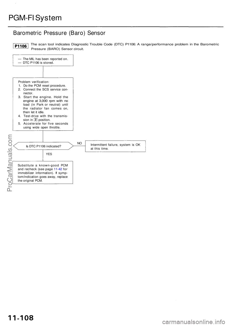
Barometri c Pressur e (Baro ) Senso r
The sca n too l indicate s Diagnosti c Troubl e Cod e (DTC ) P1106 : A range/performanc e proble m in th e Barometri c
Pressure (BARO ) Senso r circuit .
Is DT C P110 6 indicated ? Intermitten
t failure , syste m is O K
a t thi s time .
YES
Substitut e a known-goo d PC M
an d rechec k (se e pag e 11-42 fo r
immobilize r information) . I f symp -
tom/indicatio n goe s away , replac e
th e origina l PCM .
NO
Proble m verification :
1 . D o th e PC M rese t procedure .
2 . Connec t th e SC S servic e con -
nector .
3. Star t th e engine . Hol d th eengin e a t 3,00 0 rp m wit h n oloa d (i n Par k o r neutral ) unti l
th e radiato r fa n come s on ,
then le t i t idle .4. Test-driv e wit h th e transmis -sion i n position .
5 . Accelerat e fo r fiv e second s
usin g wid e ope n throttle .
—
Th e MI L ha s bee n reporte d on .
— DT C P110 6 is stored .
ProCarManuals.com
Page 612 of 1954
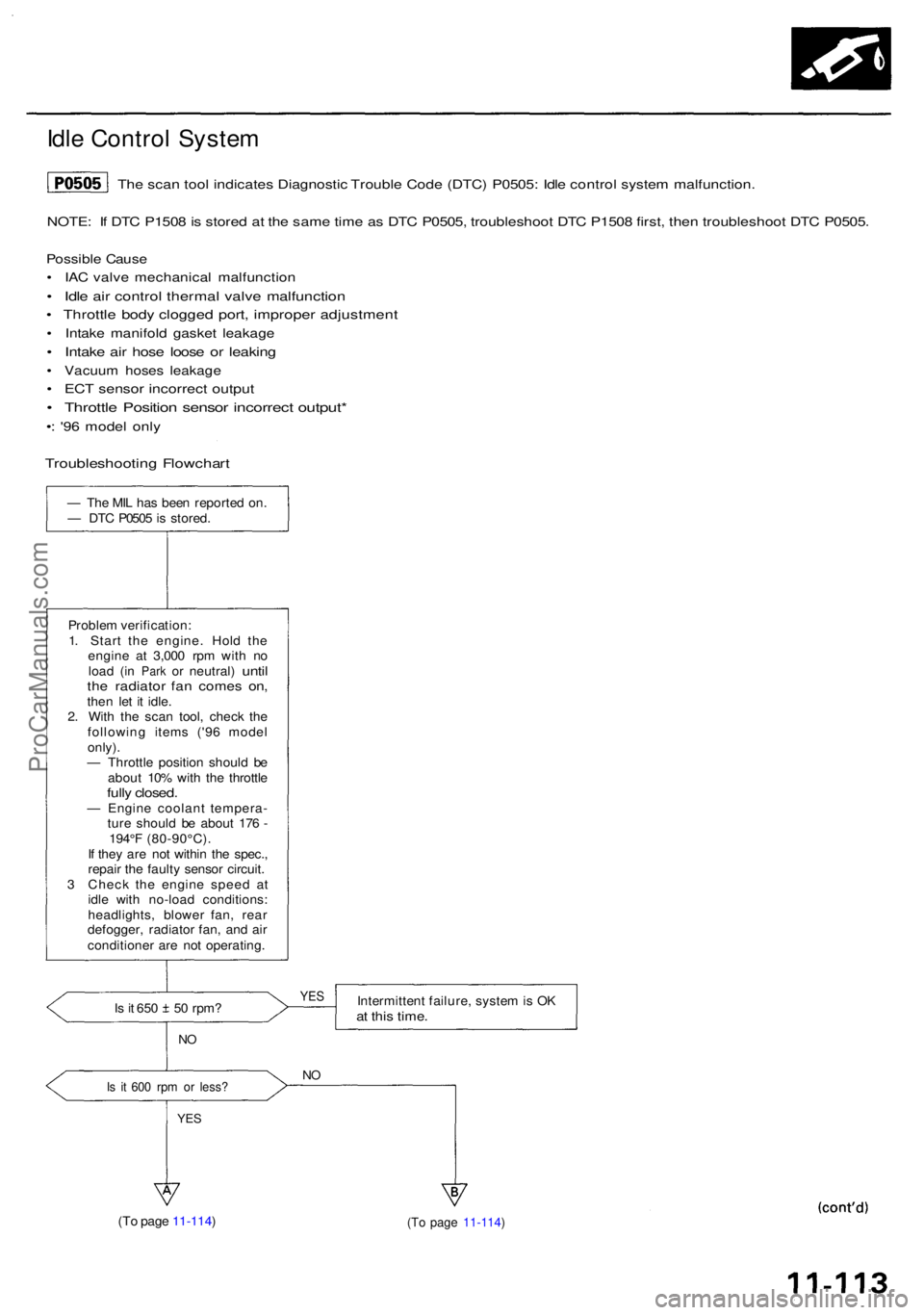
Idle Contro l Syste m
NOTE: I f DT C P150 8 is store d a t th e sam e tim e a s DT C P0505 , troubleshoo t DT C P150 8 first , the n troubleshoo t DT C P0505 .
Possibl e Caus e
• IA C valv e mechanica l malfunctio n
• Idl e ai r contro l therma l valv e malfunctio n
• Throttl e bod y clogge d port , imprope r adjustmen t
• Intak e manifol d gaske t leakag e
• Intak e ai r hos e loos e o r leakin g
• Vacuu m hose s leakag e
• EC T senso r incorrec t outpu t
• Throttl e Positio n senso r incorrec t output *
•: '9 6 mode l onl y
— Th e MI L ha s bee n reporte d on .
— DT C P050 5 is stored .
Proble m verification :
1 . Star t th e engine . Hol d th e
engin e a t 3,00 0 rp m wit h n o
loa d
(in Par k or neutral ) untilthe radiato r fa n come s on ,then le t i t idle .
2 . Wit h th e sca n tool , chec k th e
followin g item s ('9 6 mode l
only) .
— Throttl e positio n shoul d b e
abou t 10 % wit h th e throttl e
fully closed .— Engin e coolan t tempera -
tur e shoul d b e abou t 17 6 -
194° F (80-90°C) .
I f the y ar e no t withi n th e spec. ,
repai r th e fault y senso r circuit .
3 Chec k th e engin e spee d a t
idl e wit h no-loa d conditions :
headlights , blowe r fan , rea r
defogger , radiato r fan , an d ai r
conditione r ar e no t operating .
Is i t 65 0 5 0 rpm ?
NO
Is i t 60 0 rp m o r less ?
YES
Intermitten t failure , syste m is O Kat thi s time .
NO
(T o pag e 11-114 ) (T o pag e 11-114 )
YES
The sca n too l indicate s Diagnosti c Troubl e Cod e (DTC ) P0505 : Idl e contro l syste m malfunction .
Troubleshootin g Flowchar t
ProCarManuals.com
Page 614 of 1954
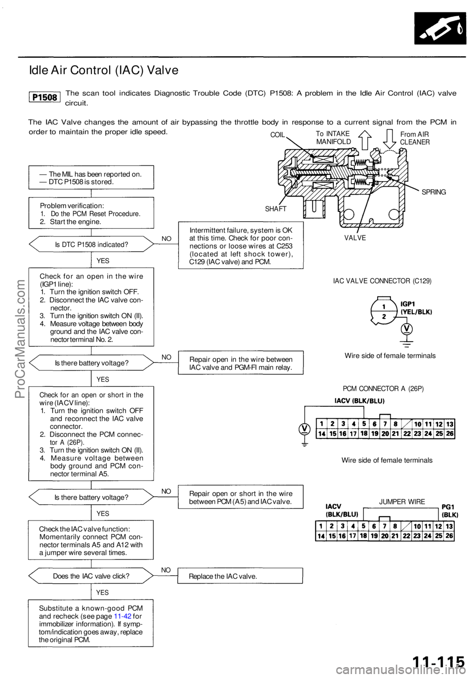
— Th e MI L ha s bee n reporte d on .
— DT C P150 8 is stored .
Proble m verification :
1. D o th e PC M Rese t Procedure .2. Star t th e engine .
Is DT C P150 8 indicated ?
YES
Chec k fo r a n ope n i n the wire
(IGP 1 line) :
1 . Tur n th e ignitio n switc h OFF .
2 . Disconnec t th e IA C valv e con -
nector .
3 . Tur n th e ignitio n switc h O N (II) .
4 . Measur e voltag e betwee n bod y
groun d an d th e IA C valv e con -
necto r termina l No . 2 .
I s ther e batter y voltage ?
I s ther e batter y voltage ?
YES
Chec k th e IA C valv e function :
Momentaril y connec t PC M con -
necto r terminal s A 5 an d A1 2 wit h
a jumpe r wire severa l times .
Doe s th e IA C valv e click ?
YES
Substitut e a known-goo d PC M
an d rechec k (se e pag e 11-42 fo r
immobilize r information) . I f symp -
tom/indicatio n goe s away , replac e
th e origina l PCM .
SHAF T
Intermitten t failure , syste m is O K
a t thi s time . Chec k fo r poo r con -
nection s o r loos e wire s a t C25 3
(locate d a t lef t shoc k tower) ,
C12 9 (IA C valve ) an d PCM .
SPRIN G
IAC VALV E CONNECTO R (C129 )
Repair ope n in th e wir e betwee n
IA C valv e an d PGM-F I mai n relay . Wir
e sid e o f femal e terminal s
PCM CONNECTO R A (26P )
Repai r ope n o r shor t i n th e wir e
betwee n PC M (A5 ) an d IA C valve . Wir
e sid e o f femal e terminal sJUMPER WIR E
Replac e th e IA C valve .NO
NO
Chec k fo r a n ope n o r shor t i n th ewir e (IAC V line) :
1 . Tur n th e ignitio n switc h OF F
an d reconnec t th e IA C valv e
connector .2. Disconnec t th e PC M connec -tor A (26P) .3. Tur n th e ignitio n switc h O N (II) .
4 . Measur e voltag e betwee n
bod y groun d an d PC M con -
necto r termina l A5 .
NO
YE S
VALV E
To INTAK EMANIFOL DFrom AI RCLEANE RCOIL
NO
Idl e Ai r Contro l (IAC ) Valv e
The sca n too l indicate s Diagnosti c Troubl e Cod e (DTC ) P1508 : A proble m in th e Idl e Ai r Contro l (IAC ) valv e
circuit .
The IA C Valv e change s th e amoun t o f ai r bypassin g th e throttl e bod y i n respons e t o a curren t signa l fro m th e PC M in
orde r t o maintai n th e prope r idl e speed .
ProCarManuals.com