engine ACURA RL KA9 1996 Service Owners Manual
[x] Cancel search | Manufacturer: ACURA, Model Year: 1996, Model line: RL KA9, Model: ACURA RL KA9 1996Pages: 1954, PDF Size: 61.44 MB
Page 470 of 1954
Oil Pa n
Remova l
Engine remova l i s no t require d i n thi s procedure .
• Mak e sur e jack s an d safet y stand s ar e place d properl y
(se e sectio n 1 ).
• Appl y th e parkin g brak e an d bloc k th e rea r wheel s s o
th e vehicl e wil l no t rol l of f stand s whil e yo u ar e
workin g unde r it .
CAUTION :
• Us e fende r cover s t o avoi d damagin g painte d sur -
faces .
• Unplu g th e wirin g connector s carefull y whil e holdin g
th e connecto r portio n to avoi d damaging .
• Mar k al l wirin g an d hose s t o avoi d misconnection .
Also , b e sur e tha t the y d o no t contac t othe r wirin g
o r hose s o r interfer e wit h othe r parts .
1 . Loose n th e idle r pulle y cente r nu t an d adjustin g bolt ,
the n remov e th e ai r conditionin g (A/C ) compresso r
bel t (se e pag e 5-7 ).
2 . Disconnec t th e powe r steerin g pressur e (PSP )
switc h connector , the n remov e th e powe r steerin g
pum p bel t an d pum p (se e pag e 5-8 ).
3 . Remov e th e lef t an d righ t sid e exhaus t manifol d
covers (se e pag e 9-4 ).
4 . Rais e th e hois t t o ful l height .
5 . Remov e th e fron t tires/wheel s an d splas h shiel d
(se e pag e 5-8 ).
6 . Remov e th e dampe r fork s (se e sectio n 18 ).
7 . Disconnec t th e suspensio n lowe r ar m bal l joint s
with the specia l tool . Refe r t o sectio n 1 8 fo r th e
prope r procedure .
8 . Remov e th e driveshaft s an d intermediat e shaf t (se e
sectio n 16 ).
9 . Drai n th e differentia l oil . Reinstal l th e drai n plu g usin g
a ne w washe r (se e sectio n 15 ).
10 . Drai n th e engin e oil . Reinstal l th e drai n bol t usin g a
ne w washe r (se e pag e 8-4 ).
11 . Disconnec t th e vehicl e spee d senso r (VSS ) connec -
tor , the n remov e th e VSS/powe r steerin g spee d
senso r (se e pag e 5-9 ).
D o no t disconnec t th e flui d hoses .
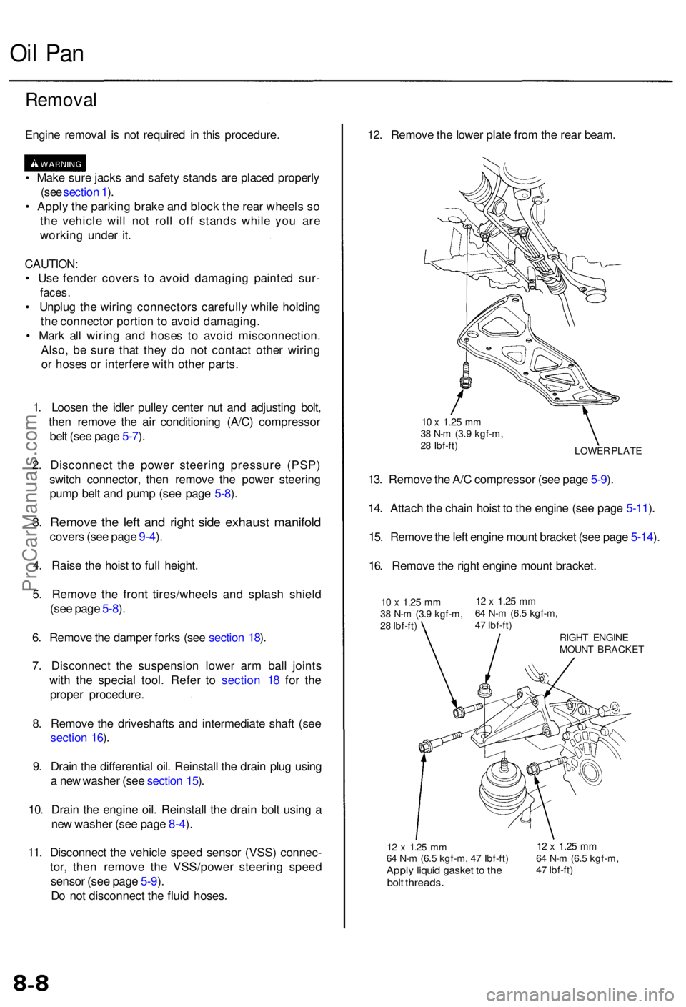
12 x 1.2 5 mm64 N- m (6. 5 kgf-m , 4 7 Ibf-ft )Apply liqui d gaske t t o th ebol t threads .
12 x 1.2 5 mm64 N- m (6. 5 kgf-m ,
4 7 Ibf-ft )
12. Remov e th e lowe r plat e fro m th e rea r beam .
LOWE R PLAT E
10 x 1.2 5 mm38 N- m (3. 9 kgf-m ,
2 8 Ibf-ft )
13. Remov e th e A/ C compresso r (se e pag e 5-9 ).
14 . Attac h th e chai n hois t t o th e engin e (se e pag e 5-11 ).
15 . Remov e th e lef t engin e moun t bracke t (se e pag e 5-14 ).
16 . Remov e th e righ t engin e moun t bracket .
10 x 1.2 5 mm38 N- m (3. 9 kgf-m ,
2 8 Ibf-ft )12 x 1.2 5 mm64 N- m (6. 5 kgf-m ,
4 7 Ibf-ft )
RIGHT ENGIN E
MOUN T BRACKE T
ProCarManuals.com
Page 472 of 1954
Oil Pan
Installation
Install the oil pan in the reverse order of removal:
• Always use new O-rings.
• Oil pan and cylinder block mating surface must be
clean.
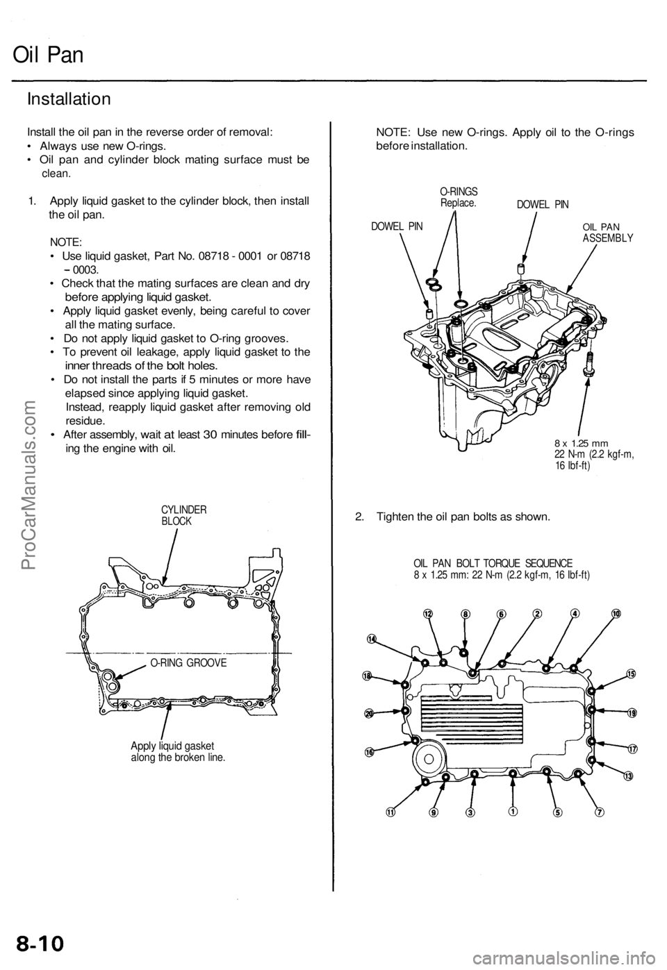
1. Apply liquid gasket to the cylinder block, then install
the oil
pan.
NOTE:
• Use liquid gasket, Part No. 08718 - 0001 or 08718
0003.
• Check that the mating surfaces are clean and dry
before applying liquid gasket.
• Apply liquid gasket evenly, being careful to cover
all the mating surface.
• Do not apply liquid gasket to O-ring grooves.
• To prevent oil leakage, apply liquid gasket to the
inner threads of the bolt holes.
• Do not install the parts if 5 minutes or more have
elapsed since applying liquid gasket.
Instead, reapply liquid gasket after removing old
residue.
•
After assembly,
wait
at
least
30
minutes before
fill-
ing the engine with oil.
CYLINDER
BLOCK
O-RING GROOVE
Apply liquid gasket
along the broken line.
NOTE: Use new O-rings. Apply oil to the O-rings
before installation.
DOWEL PIN
O-RINGS
Replace.
DOWEL PIN
OIL PAN
ASSEMBLY
8 x
1.25
mm
22 N-m (2.2 kgf-m,
16 Ibf-ft)
2. Tighten the oil pan bolts as shown.
OIL PAN BOLT TORQUE SEQUENCE
8 x 1.25 mm: 22 N-m (2.2 kgf-m, 16 Ibf-ft)ProCarManuals.com
Page 473 of 1954
3. Instal l th e differentia l assembly .
Selec t th e appropriat e 2 6 m m shi m wheneve r th e
oi l pa n o r th e cylinde r bloc k i s replaced .
Refe r t o sectio n 1 5 fo r selectio n o f th e correc t
26 m m shim .
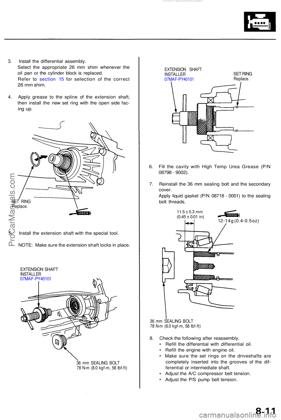
4. Appl y greas e t o th e splin e o f th e extensio n shaft ,
the n instal l th e ne w se t rin g wit h th e ope n sid e fac -
ing up .
EXTENSIO N SHAF T
INSTALLE R
07MA F-PY4010 1SET RIN GReplace .
6. Fil l th e cavit y wit h Hig h Tem p Ure a Greas e (P/ N
0879 8 - 9002) .
7 . Reinstal l th e 3 6 m m sealin g bol t an d th e secondar y
cover .
Appl y liqui d gaske t (P/ N 0871 8 - 0001 ) t o th e sealin g
bol t threads .
11.5 ± 0. 3 m m(0.4 5 ± 0.01 in)12 -1 4 g (0.4-0. 5 oz )
36 m m SEALIN G BOL T
7 8 N- m (8. 0 kgf-m , 5 8 Ibf-ft )
8. Chec k th e followin g afte r reassembly .
• Refil l th e differentia l wit h differentia l oil .
• Refil l th e engine with engin e oil .
• Mak e sur e th e se t ring s o n th e driveshaft s ar e
completel y inserte d int o th e groove s o f th e dif -
ferentia l o r intermediat e shaft .
• Adjus t th e A/ C compresso r bel t tension .
• Adjus t th e P/ S pum p bel t tension .
36 m m SEALIN G BOL T
7 8 N- m (8. 0 kgf-m , 5 8 Ibf-ft )
EXTENSIO N SHAF TINSTALLE R07MAF-PY4010 1
5. Instal l th e extensio n shaf t wit h th e specia l tool .
NOTE : Mak e sur e th e extensio n shaf t lock s in place .
SET RIN G
Replace .
ProCarManuals.com
Page 475 of 1954
Removal/lnspection/lnstallation
NOTE: To remove the oil pump, the engine must be
removed from the vehicle and separated from the trans-
mission.
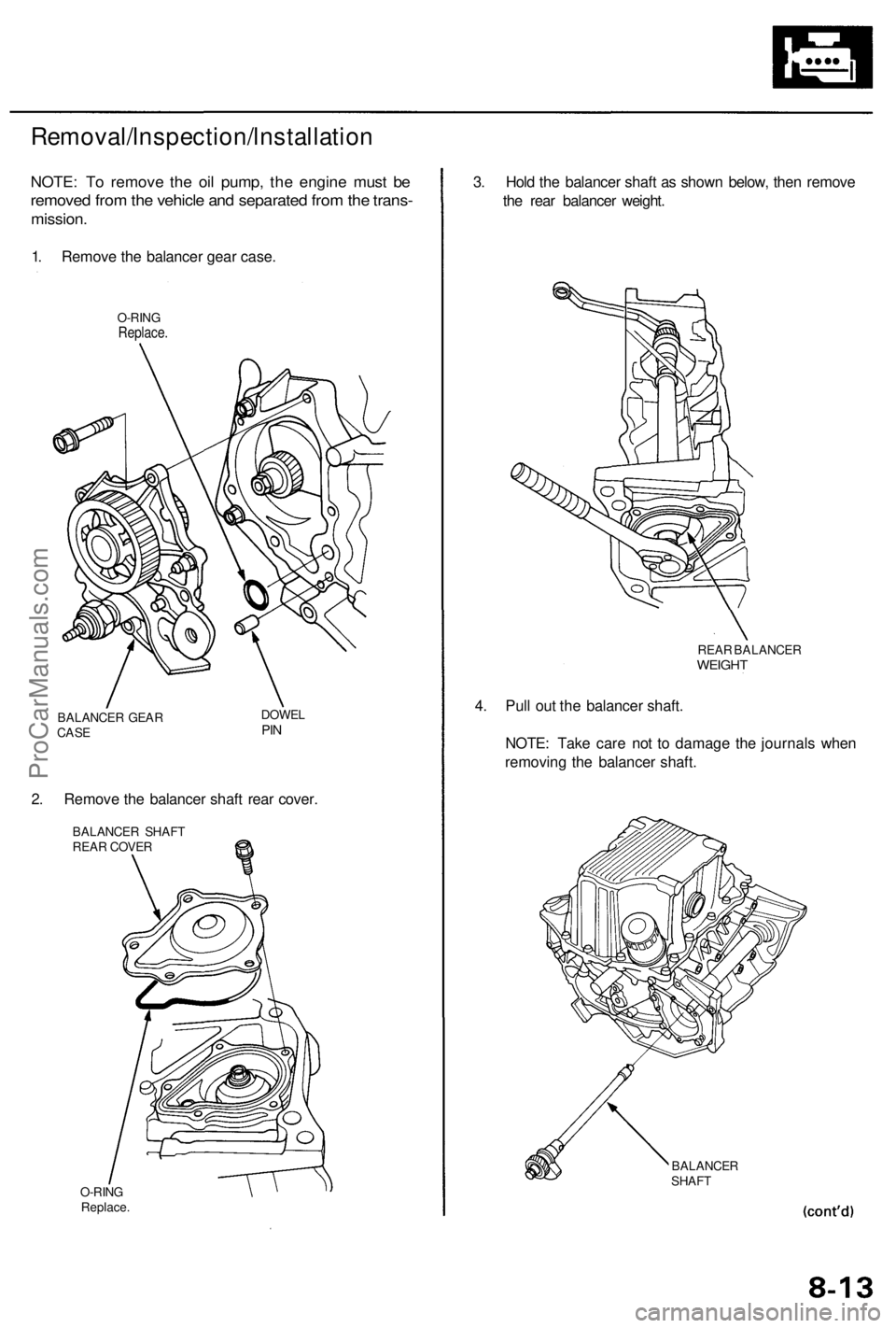
1. Remove the balancer gear case.
O-RING
Replace.
BALANCER GEAR
CASE
DOWEL
PIN
2. Remove the balancer shaft rear cover.
BALANCER SHAFT
REAR COVER
O-RING
Replace.
BALANCER
SHAFT
3. Hold the balancer shaft as shown below, then remove
the rear balancer weight.
4. Pull out the balancer shaft.
NOTE: Take care not to damage the journals when
removing the balancer shaft.
REAR BALANCER
WEIGHTProCarManuals.com
Page 487 of 1954
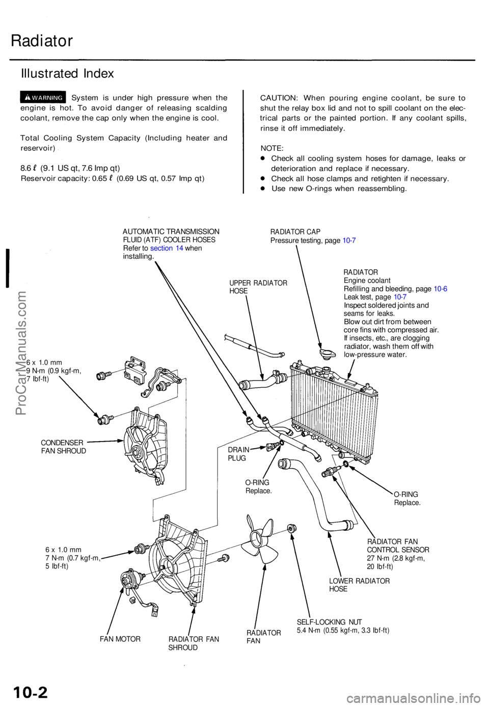
Radiator
Illustrate d Inde x
Syste m is unde r hig h pressur e whe n th e
engin e i s hot . T o avoi d dange r o f releasin g scaldin g
coolant , remov e th e ca p onl y whe n th e engin e is cool .
Tota l Coolin g Syste m Capacit y (Includin g heate r an d
reservoir )
8.6 (9. 1 US qt , 7. 6 Im p qt )
Reservoi r capacity : 0.6 5 (0.6 9 U S qt , 0.5 7 Im p qt ) CAUTION
: Whe n pourin g engin e coolant , b e sur e t o
shu t th e rela y bo x li d an d no t t o spil l coolan t o n th e elec -
trica l part s o r th e painte d portion . I f an y coolan t spills ,
rins e it of f immediately .
NOTE:
Check al l coolin g syste m hose s fo r damage , leak s o r
deterioratio n an d replac e if necessary .
Chec k al l hos e clamp s an d retighte n i f necessary .
Us e ne w O-ring s whe n reassembling .
AUTOMATIC TRANSMISSIO NFLUID (ATF ) COOLE R HOSE SRefer t o sectio n 1 4 whe ninstalling .
RADIATO R CA PPressur e testing , pag e 10-7
6 x 1. 0 m m9 N- m (0. 9 kgf-m ,7 Ibf-ft )
RADIATO REngine coolan tRefilling an d bleeding , pag e 10-6Lea k test , pag e 10-7Inspec t soldere d joint s an dseam s fo r leaks .Blow ou t dir t fro m betwee ncore fin s wit h compresse d air .If insects , etc. , ar e cloggin gradiator, was h the m of f wit hlow-pressur e water .
CONDENSE RFAN SHROU D
6 x 1. 0 m m7 N- m (0. 7 kgf-m ,5 Ibf-ft )
O-RIN GReplace .
RADIATO R FA NCONTRO L SENSO R27 N- m (2. 8 kgf-m ,20 Ibf-ft )
FAN MOTO RRADIATO R FA NSHROU D
RADIATO RFAN
LOWE R RADIATO RHOSE
SELF-LOCKIN G NU T5.4 N- m (0.5 5 kgf-m , 3. 3 Ibf-ft )
O-RIN GReplace .
DRAINPLUG
UPPE R RADIATO RHOSE
ProCarManuals.com
Page 488 of 1954
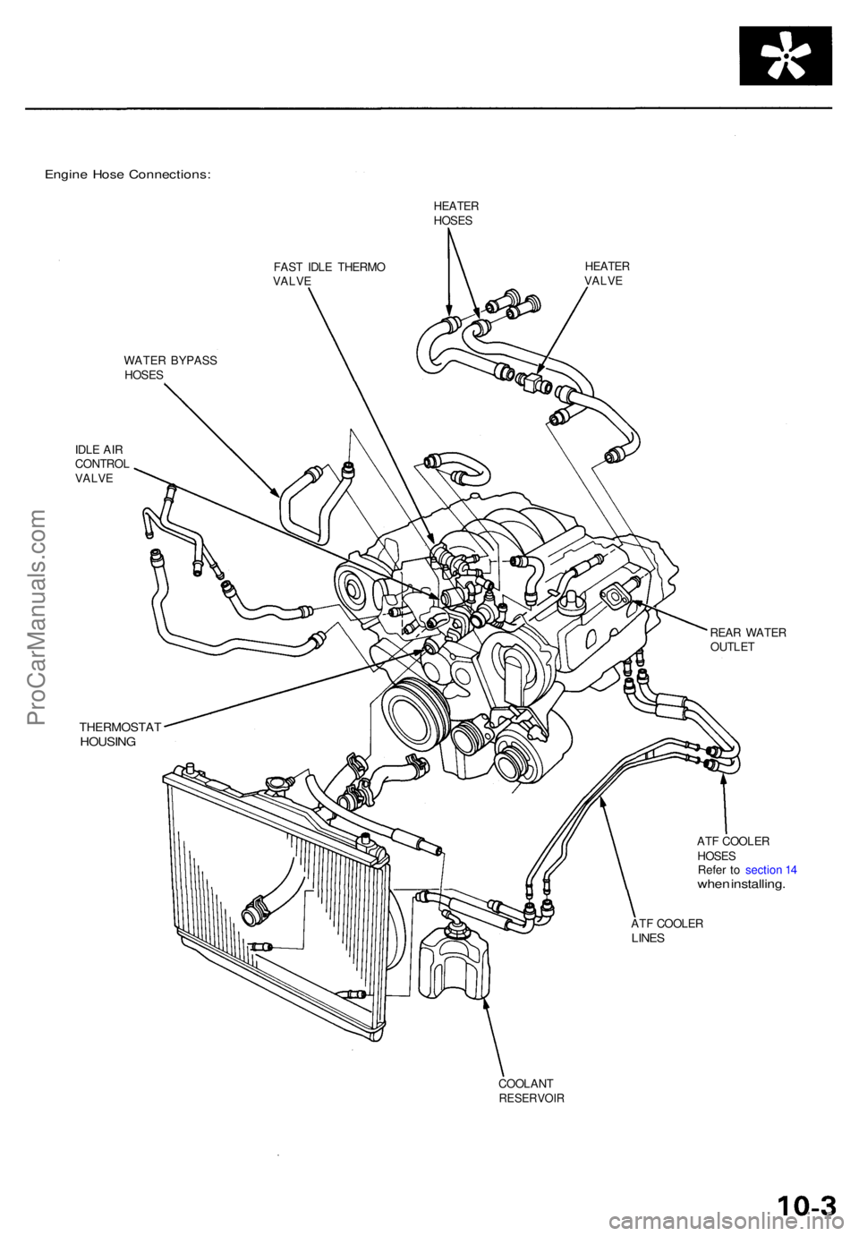
Engine Hos e Connections :
HEATERHOSES
FAS T IDL E THERM O
VALV E
HEATE RVALVE
WATE R BYPAS S
HOSE S
IDL E AI R
CONTRO L
VALV E
THERMOSTA THOUSING
REAR WATE R
OUTLE T
AT F COOLE R
HOSE S
Refe r t o sectio n 1 4
whe n installing .
ATF COOLE RLINES
COOLAN TRESERVOI R
ProCarManuals.com
Page 490 of 1954
Engine Coolan t Refillin g an d Bleedin g
'96 -0 0 models :
CAUTION : Whe n pourin g engin e coolant , b e sur e t o
shu t th e rela y bo x li d an d no t t o le t coolan t spil l o n th e
electrica l part s o r th e paint . I f an y coolan t spills , rins e it
of f immediately .
NOTE:
Perfor m thi s procedur e whe n th e engin e is cool .
Befor e replacin g th e coolant , tur n th e ignitio n O N (II) ,
slowl y tur n th e climat e contro l temperatur e kno b t o
90° , an d tur n of f th e ignition . Thi s wil l allo w th e
coolan t i n th e heate r t o drai n ou t wit h th e res t o f th e
system .
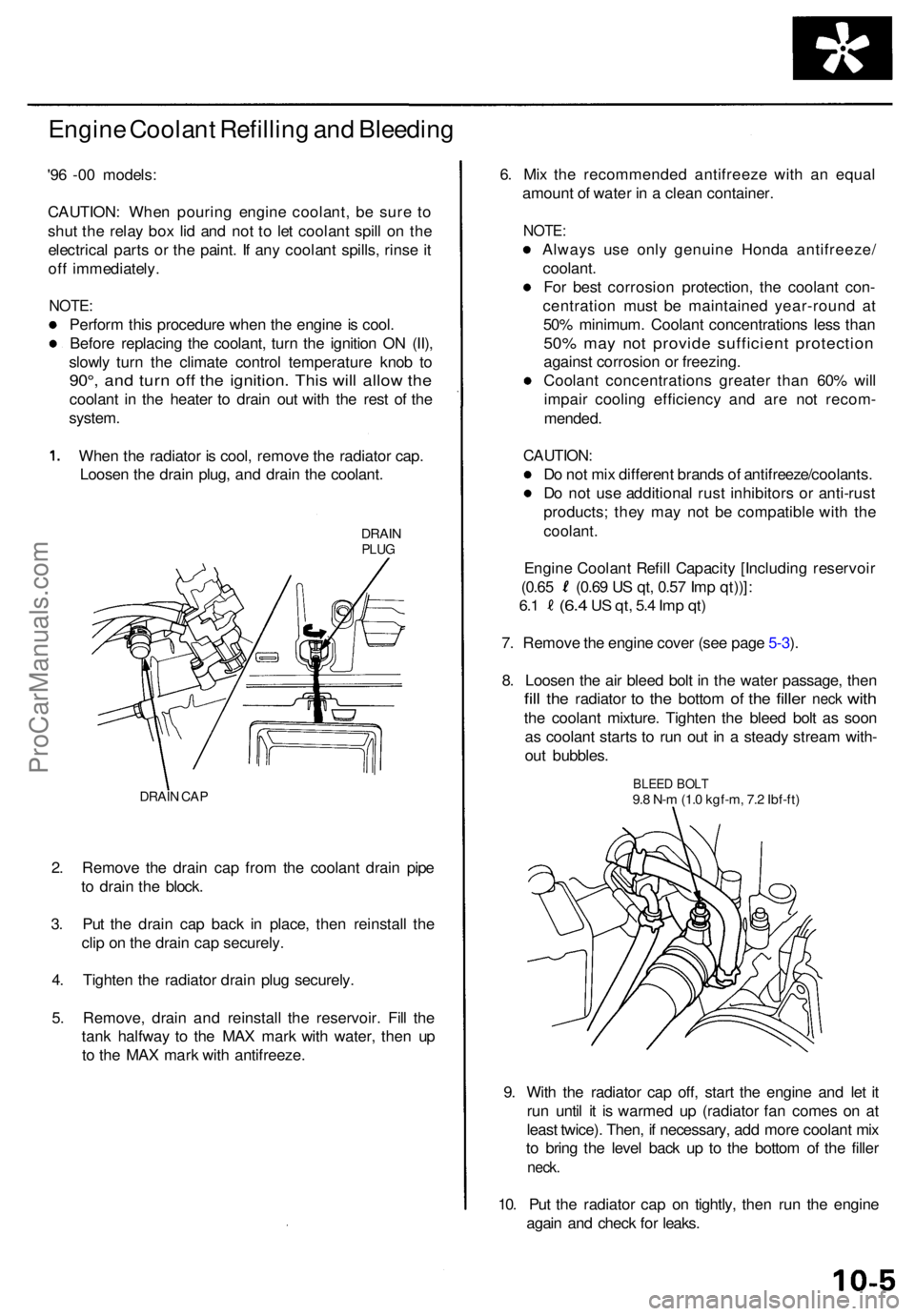
Whe n th e radiato r i s cool , remov e th e radiato r cap .
Loose n th e drai n plug , an d drai n th e coolant .
DRAINPLUG
DRAI N CA P
2. Remov e th e drai n cap from th e coolan t drai n pip e
t o drai n th e block .
3 . Pu t th e drai n ca p bac k i n place , the n reinstal l th e
cli p o n th e drai n ca p securely .
4 . Tighte n th e radiato r drai n plu g securely .
5 . Remove , drai n an d reinstal l th e reservoir . Fil l th e
tan k halfwa y t o th e MA X mar k wit h water , the n u p
t o th e MA X mar k wit h antifreeze . 6
. Mi x th e recommende d antifreez e wit h a n equa l
amoun t o f wate r i n a clea n container .
NOTE:
Alway s us e onl y genuin e Hond a antifreeze /
coolant .
Fo r bes t corrosio n protection , th e coolan t con -
centratio n mus t b e maintaine d year-roun d a t
50 % minimum . Coolan t concentration s les s tha n
50% ma y no t provid e sufficien t protectio n
against corrosio n o r freezing .
Coolan t concentration s greate r tha n 60 % wil l
impai r coolin g efficienc y an d ar e no t recom -
mended .
CAUTION :
Do no t mi x differen t brand s o f antifreeze/coolants .
D o no t us e additiona l rus t inhibitor s o r anti-rus t
products ; the y ma y no t b e compatibl e wit h th e
coolant .
Engine Coolan t Refil l Capacit y [Includin g reservoi r
(0.65 (0.6 9 U S qt , 0.5 7 Im p qt))] :
6.1 (6. 4 US qt , 5. 4 Im p qt )
7. Remov e th e engin e cove r (se e pag e 5-3 ).
8 . Loose n th e ai r blee d bol t i n th e wate r passage , the n
fill th e radiato r to th e botto m of th e fille r nec k with
the coolan t mixture . Tighte n th e blee d bol t a s soo n
a s coolan t start s t o ru n ou t i n a stead y strea m with -
ou t bubbles .
9 . Wit h th e radiato r ca p off , star t th e engin e an d le t i t
ru n unti l i t i s warme d u p (radiato r fa n come s o n a t
leas t twice) . Then , i f necessary , ad d mor e coolan t mi x
t o brin g th e leve l bac k u p t o th e botto m o f th e fille r
neck .
10. Pu t th e radiato r ca p o n tightly , the n ru n th e engin e
agai n an d chec k fo r leaks .
BLEE D BOL T9.8 N- m (1. 0 kgf-m , 7. 2 Ibf-ft )
ProCarManuals.com
Page 491 of 1954
Radiator
Engine Coolan t Refillin g an d Bleedin g
'01 model :
CAUTION : Whe n pourin g engin e coolant , b e sur e t o
shu t th e rela y bo x li d an d no t t o le t coolan t spil l o n th e
electrica l part s o r th e paint . I f an y coolan t spills , rins e it
of f immediately .
NOTE:
Perfor m thi s procedur e whe n th e engin e is cool .
Befor e replacin g th e coolant , tur n th e ignitio n O N (II) ,
slowl y tur n th e climat e contro l temperatur e kno b t o
90° , an d tur n of f th e ignition . Thi s wil l allo w th e
coolan t i n th e heate r t o drai n ou t wit h th e res t o f th e
system .
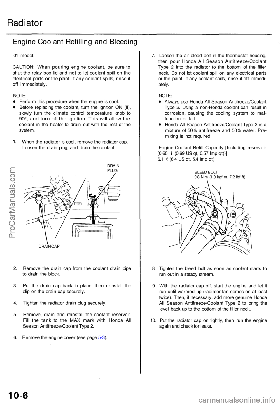
Whe n th e radiato r i s cool , remov e th e radiato r cap .
Loose n th e drai n plug , an d drai n th e coolant .
DRAINPLUG
DRAI N CA P
2. Remov e th e drai n ca p fro m th e coolan t drai n pip e
t o drai n th e block .
3 . Pu t th e drai n ca p bac k i n place , the n reinstal l th e
cli p o n th e drai n ca p securely .
4 . Tighte n th e radiato r drai n plu g securely .
5 . Remove , drai n an d reinstal l th e coolan t reservoir .
Fil l th e tan k t o th e MA X mar k wit h Hond a Al l
Seaso n Antifreeze/Coolan t Typ e 2 .
6 . Remov e th e engine cover (se e pag e 5-3 ). 7
. Loose n th e ai r blee d bol t i n th e thermosta t housing ,
the n pou r Hond a Al l Seaso n Antifreeze/Coolan t
Typ e 2 int o th e radiato r t o th e botto m o f th e fille r
neck . D o no t le t coolan t spil l o n an y electrica l part s
o r th e paint . I f an y coolan t spills , rins e i t of f immedi -
ately .
NOTE :
Alway s us e Hond a Al l Seaso n Antifreeze/Coolan t
Typ e 2 . Usin g a non-Hond a coolan t ca n resul t i n
corrosion , causin g th e coolin g syste m to mal -
functio n o r fail .
Hond a Al l Seaso n Antifreeze/Coolan t Typ e 2 is a
mixtur e o f 50 % antifreez e an d 50 % water . Pre -
mixin g i s no t required .
8 . Tighte n th e blee d bol t a s soo n a s coolan t start s t o
ru n ou t i n a stead y stream .
9 . Wit h th e radiato r cap off, star t th e engin e an d le t i t
ru n unti l warme d u p (radiato r fa n come s o n a t leas t
twice) . Then , i f necessary , ad d mor e genuin e Hond a
Al l Seaso n Antifreeze/Coolan t Typ e 2 to brin g th e
leve l bac k u p t o th e botto m o f th e fille r neck .
10 . Pu t th e radiato r ca p o n tightly , the n ru n th e engin e
agai n an d chec k fo r leaks .
Engin
e Coolan t Refil l Capacit y [Includin g reservoi r
(0.65 (0.6 9 U S qt , 0.5 7 Im p qt))] :
6.1 (6. 4 US qt , 5. 4 Im p qt )
BLEE D BOL T9.8 N- m (1. 0 kgf-m , 7. 2 Ibf-ft )
ProCarManuals.com
Page 492 of 1954
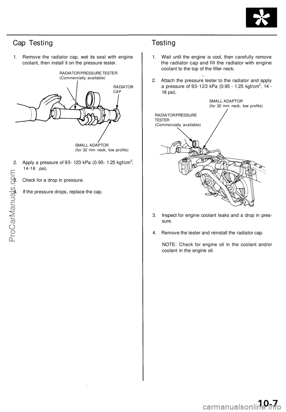
Cap Testing
Testing
1. Remove the radiator cap, wet its seal with engine
coolant, then install it on the pressure tester.
RADIATOR
CAP
2. Apply a pressure of 93- 123 kPa (0.95- 1.25 kgf/cm2,
14-18 psi).
3. Check for a drop in pressure.
4. If the pressure drops, replace the cap.
1. Wait until the engine is cool, then carefully remove
the radiator cap and fill the radiator with engine
coolant to the top of the filler neck.
2. Attach the pressure tester to the radiator and apply
a pressure of 93-123 kPa (0.95 - 1.25 kgf/cm2, 14 -
18
psi).
RADIATOR PRESSURE
TESTER
(Commercially available)
3. Inspect for engine coolant leaks and a drop in pres-
sure.
4. Remove the tester and reinstall the radiator cap.
NOTE: Check for engine oil in the coolant and/or
coolant in the engine oil.
RADIATOR PRESSURE TESTER
(Commercially available)
SMALL ADAPTOR
(for 32 mm neck, low profile)
SMALL ADAPTOR
(for 32 mm neck, low profile)ProCarManuals.com
Page 493 of 1954
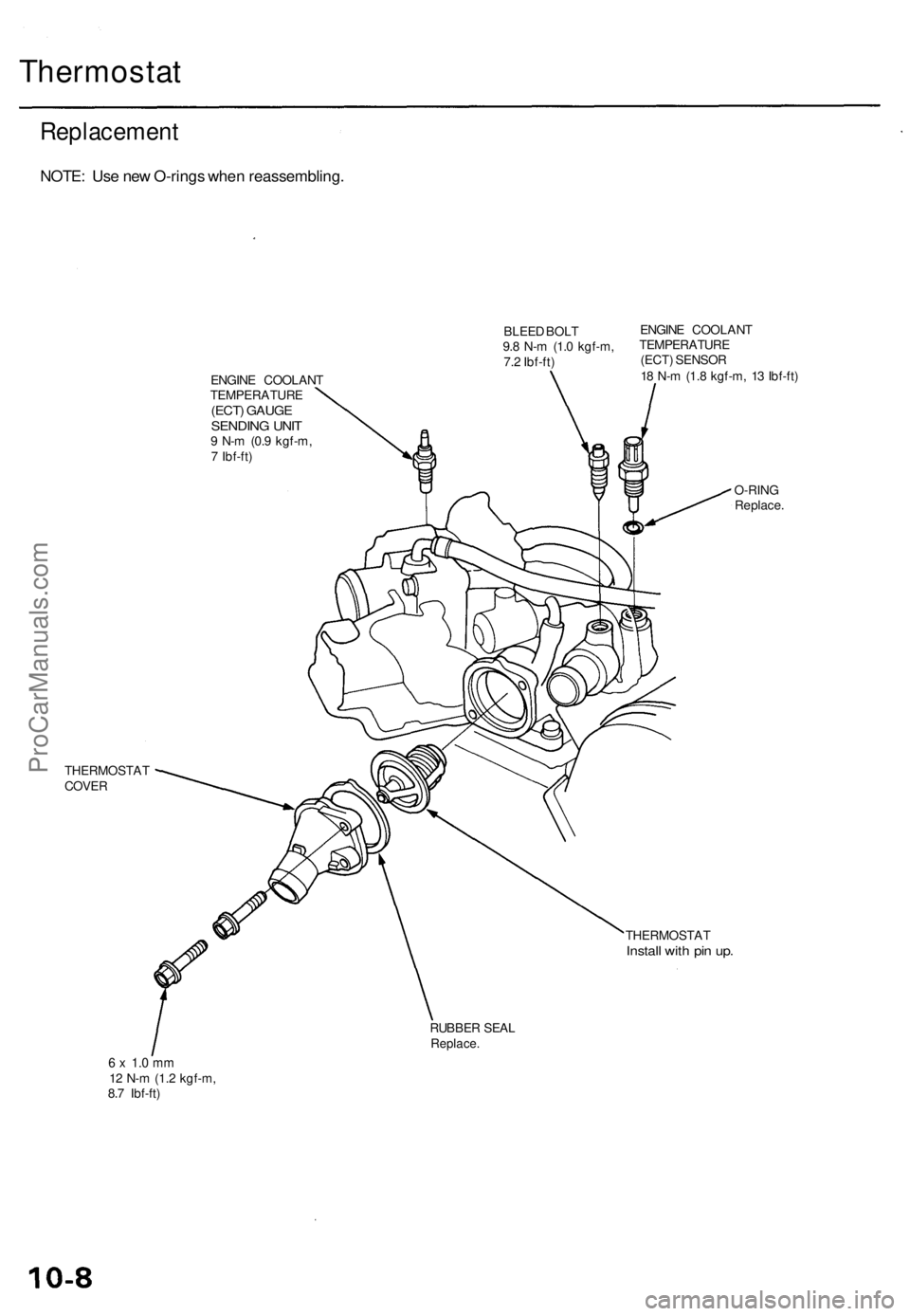
Thermostat
Replacement
NOTE: Use new O-rings when reassembling.
BLEED BOLT
9.8 N-m (1.0 kgf-m,
7.2 Ibf-ft)
ENGINE COOLANT
TEMPERATURE
(ECT) GAUGE
SENDING UNIT
9 N-m (0.9 kgf-m,
7 Ibf-ft)
ENGINE COOLANT
TEMPERATURE
(ECT) SENSOR
18 N-m (1.8 kgf-m, 13 Ibf-ft)
THERMOSTAT
COVER
O-RING
Replace.
THERMOSTAT
Install with pin up.
RUBBER SEAL
Replace.
6 x 1.0 mm
12 N-m (1.2 kgf-m,
8.7 Ibf-ft)ProCarManuals.com