ACURA RL KA9 1996 Service Repair Manual
Manufacturer: ACURA, Model Year: 1996, Model line: RL KA9, Model: ACURA RL KA9 1996Pages: 1954, PDF Size: 61.44 MB
Page 1731 of 1954
Description
Navigation Functio n (cont'd )
Yaw Rat e Senso r
Th e ya w rat e senso r detect s th e directio n chang e (angula r speed ) o f th e vehicle . Th e senso r i s a n oscillatio n gyr o buil t int o
the navigatio n unit .
Senso r Elemen t Structur e
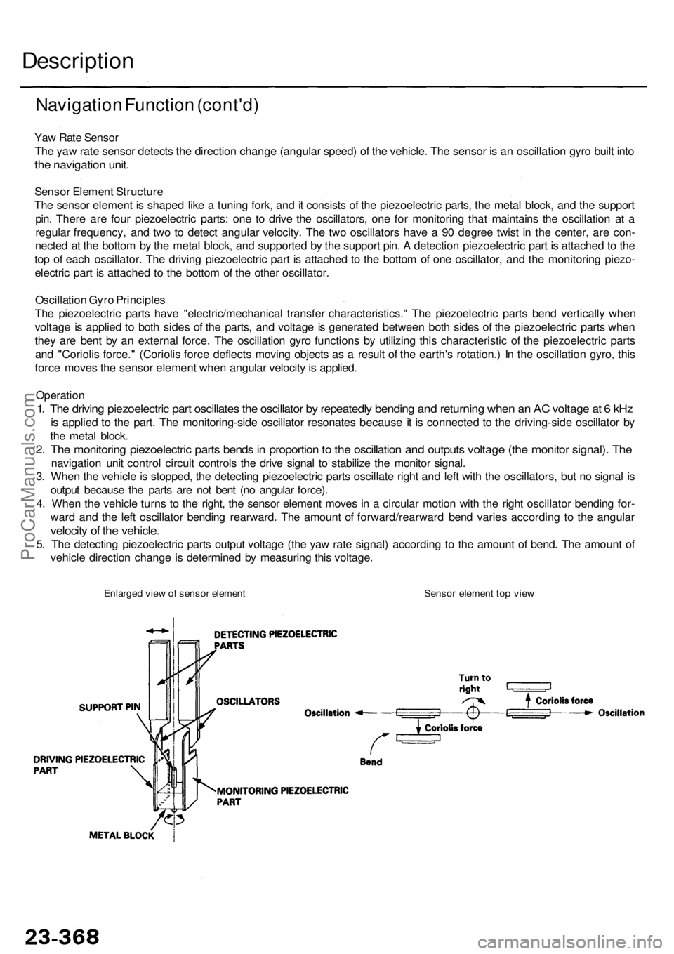
Th e senso r elemen t i s shape d lik e a tunin g fork , an d it consist s o f th e piezoelectri c parts , th e meta l block , an d th e suppor t
pin . Ther e ar e fou r piezoelectri c parts : on e t o driv e th e oscillators , on e fo r monitorin g tha t maintain s th e oscillatio n a t a
regula r frequency , an d tw o t o detec t angula r velocity . Th e tw o oscillator s hav e a 90 degre e twis t i n th e center , ar e con -
necte d a t th e botto m b y th e meta l block , an d supporte d b y th e suppor t pin . A detectio n piezoelectri c par t i s attache d to th e
to p o f eac h oscillator . Th e drivin g piezoelectri c par t i s attache d t o th e botto m o f on e oscillator , an d th e monitoring piezo-
electri c par t i s attache d t o th e botto m o f th e othe r oscillator .
Oscillatio n Gyr o Principle s
Th e piezoelectri c part s hav e "electric/mechanica l transfe r characteristics. " Th e piezoelectri c part s ben d verticall y whe n
voltag e is applie d t o bot h side s o f th e parts , an d voltag e is generate d betwee n bot h side s o f th e piezoelectri c part s whe n
the y ar e ben t b y a n externa l force . Th e oscillatio n gyr o function s b y utilizin g thi s characteristi c o f th e piezoelectri c part s
an d "Corioli s force. " (Corioli s forc e deflect s movin g object s a s a resul t o f th e earth' s rotation. ) I n th e oscillation gyro, thi s
forc e move s th e senso r elemen t whe n angula r velocit y is applied .
Operatio n
1. Th e drivin g piezoelectri c par t oscillate s th e oscillato r b y repeatedl y bendin g an d returnin g whe n a n A C voltag e a t 6 kH z
is applie d t o th e part . Th e monitoring-sid e oscillato r resonate s becaus e it i s connecte d t o th e driving-sid e oscillato r b y
th e meta l block .
2. Th e monitorin g piezoelectri c part s bend s in proportio n to th e oscillatio n an d output s voltag e (th e monito r signal) . Th e
navigatio n uni t contro l circui t control s th e driv e signa l t o stabiliz e th e monito r signal .
3 . Whe n th e vehicl e is stopped , th e detectin g piezoelectri c part s oscillat e righ t an d lef t wit h th e oscillators , bu t n o signa l i s
outpu t becaus e th e part s ar e no t ben t (n o angula r force) .
4 . Whe n th e vehicl e turn s t o th e right , th e senso r elemen t move s i n a circula r motio n wit h th e righ t oscillato r bendin g for -
war d an d th e lef t oscillato r bendin g rearward . Th e amoun t o f forward/rearwar d ben d varie s accordin g t o th e angula r
velocity o f th e vehicle .
5. Th e detectin g piezoelectri c part s outpu t voltag e (th e ya w rat e signal ) accordin g t o th e amoun t o f bend . Th e amoun t o f
vehicl e directio n chang e is determine d b y measurin g thi s voltage .
Enlarged vie w o f senso r elemen t Senso r elemen t to p vie w
ProCarManuals.com
Page 1732 of 1954
GPS Antenn a
Receivin g th e electri c wave s fro m th e satellites , th e GP S antenn a amplifie s an d transmit s the m to th e GP S receiver .
GPS Receive r
The GP S receive r i s buil t i n th e navigatio n unit . I t calculate s th e vehicl e positio n b y receivin g th e signa l fro m th e GP S
antenna . Th e vehicl e positio n an d signa l receptio n conditio n is transmitte d fro m th e GP S receive r t o th e navigatio n contro l
uni t t o adjus t vehicl e position . (cont'd )
Globa
l Positionin g Syste m (GPS )
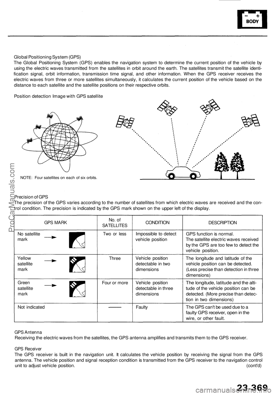
Th e Globa l Positionin g Syste m (GPS ) enable s th e navigatio n syste m to determin e th e curren t positio n o f th e vehicl e b y
usin g th e electri c wave s transmitte d fro m th e satellite s i n orbi t aroun d th e earth . Th e satellite s transmi t th e satellit e identi -
ficatio n signal , orbi t information , transmissio n tim e signal , an d othe r information . Whe n th e GP S receive r receive s th e
electri c wave s fro m thre e o r mor e satellite s simultaneously , i t calculate s th e curren t positio n o f th e vehicl e base d o n th e
distanc e to eac h satellit e an d th e satellit e position s o n thei r respectiv e orbits .
Positio n detectio n Imag e wit h GP S satellit e
NOTE: Fou r satellite s o n eac h o f si x orbits .
Precisio n o f GP S
Th e precisio n o f th e GP S varie s accordin g to th e numbe r o f satellite s fro m whic h electri c wave s ar e receive d an d th e con -
tro l condition . Th e precisio n is indicate d b y th e GP S mar k show n o n th e uppe r lef t o f th e display .
GPS MAR K
No satellit e
mark
No. o f
SATELLITE S
Two o r les s
CONDITIO N
Impossibl e t o detec t
vehicl e positio n
Three
Four o r mor e
Yello
w
satellit e
mark
Gree n
satellit e
mark
Not indicate d Vehicl
e positio n
detectabl e in tw o
dimension s
Vehicl e positio n
detectabl e in thre e
dimension sFaulty
DESCRIPTIO N
GPS functio n is normal .
Th e satellit e electri c wave s receive d
b y th e GP S ar e to o fe w to detec t th e
vehicl e position .
Th e longitud e an d latitud e o f th e
vehicl e positio n ca n b e detected .
(Les s precis e tha n detectio n in thre e
dimensions )
The longitude , latitud e an d th e alti -
tud e o f th e vehicl e positio n can be
detected . (Mor e precis e tha n detec -
tio n i n tw o dimensions )
Th e GP S can' t b e use d du e to a
fault y GP S receiver , ope n in th e
wire , o r othe r fault .
ProCarManuals.com
Page 1733 of 1954
Description
Navigation Functio n (cont'd )
Navigatio n Uni t
Th e navigatio n uni t calculate s th e vehicl e positio n an d guide s yo u t o th e destination . Th e uni t perform s ma p matchin g
correction , GP S correction , an d distanc e tuning . I t als o control s th e men u function s an d th e DVD-RO M driv e (har d dis k
drive '9 6 - 9 9 models) . Wit h contro l o f al l thes e items , th e navigatio n uni t make s th e navigatio n pictur e signal , the n it
transmit s th e signa l t o th e displa y uni t an d audi o drivin g instruction s t o th e audi o unit .
Calculatio n o f Vehicl e Positio n
Th e navigatio n uni t calculate s th e vehicl e positio n (th e drivin g directio n an d th e curren t position ) b y receivin g th e direc -
tiona l chang e signal s fro m th e ya w rat e senso r an d th e trave l distanc e signal s fro m th e vehicl e spee d senso r (VSS) .
Ma p Matchin g Tunin g
Th e ma p matchin g tunin g i s accomplishe d b y indicatin g th e vehicl e positio n o n th e road s o n th e map . Th e ma p dat a
transmitte d fro m th e DVD-RO M (har d dis k '9 6 - 9 9 models ) i s checke d agains t th e vehicl e positio n data , an d th e vehicl e
positio n i s indicate d o n th e neares t road . Ma p matchin g tunin g doe s no t occu r whe n th e vehicl e travel s o n a roa d no t
show n o n th e ma p o r whe n th e vehicl e positio n is fa r awa y fro m a roa d o n th e map .
GP S Tunin g
Th e GP S tunin g is accomplishe d b y indicatin g th e vehicl e positio n a s th e GPS' s vehicl e position . Th e navigatio n uni t com -
pare s it s calculate d vehicl e positio n dat a wit h th e GP S vehicl e positio n data . I f ther e i s larg e differenc e betwee n th e two ,
th e indicate d vehicl e positio n i s adjuste d to th e GP S vehicl e position .
Distanc e Tunin g
Th e distanc e tunin g reduce s th e differenc e betwee n th e trave l distanc e signa l fro m th e VS S an d th e distanc e dat a o n th e
map . Th e navigatio n uni t compare s it s calculate d vehicl e positio n dat a wit h th e GP S vehicl e positio n data . Th e navigatio n
uni t the n decreases the tunin g valu e whe n th e vehicl e positio n i s ahea d o f th e GP S vehicl e position , an d i t increase s th e
tunin g valu e whe n th e vehicl e positio n is behin d th e GP S vehicl e position .
Rout e Guidanc e
Th e navigatio n uni t ca n calculat e differen t route s t o a selecte d destination . Yo u hav e fou r options :
• Direct Rout e — Calculat e a route that is th e mos t direc t and will tak e the leas t time .
• Eas y Rout e — Calculat e a rout e tha t minimize s th e numbe r o f turn s needed .
• Minimiz e Freeway s — Calculat e a rout e tha t avoid s freewa y travel . I f tha t i s no t possible , kee p th e amoun t o f freewa y
trave l t o a minimum .
• Minimiz e Tol l Road s — Calculat e a rout e tha t avoid s o r minimize s trave l o n tol l road s
Audi o Guidanc e
Th e navigatio n uni t transmit s audi o drivin g instruction s befor e enterin g a n intersectio n o r passin g a junction .
Th e audi o instruction s com e throug h audi o uni t an d th e fron t speakers .
DVD-RO M ('0 0 - 0 1 models) . Har d Dis k ('9 6 - 9 9 models )
Th e ma p dat a (includin g al l scal e rates ) i s store d in th e DVD-ROM/Har d Disk . Th e ma p dat a includes :
• Roa d distances , roa d widths , spee d limits , traffi c regulations , passin g tim e a t junction , distance s t o junctions , an d th e
drivin g instruction s fo r audi o guidance .
• Latitud e an d longitud e fo r GPS .
ProCarManuals.com
Page 1734 of 1954
Audio Uni t
Th e audi o uni t receive s th e audi o drivin g instruction s fro m th e navigatio n uni t an d transmit s th e instruction s throug h th e
fron t speaker s eve n whe n th e audi o syste m is in use .
Displa y Uni t
'9 6 - 9 9 model s
Th e displa y uni t use s liqui d crysta l displa y (LCD) . Th e LC D is a 6-inch-wide , Thi n Fil m Transisto r (TFT) , strip e typ e wit h
220,00 0 pictur e elements . Th e colo r fil m an d fluorescen t ligh t ar e lai d ou t o n th e bac k o f th e liqui d crysta l film . Th e touc h
senso r o n th e fron t o f th e LC D is a n infrare d typ e wit h nin e vertica l an d nin e horizonta l infrare d ray s t o produc e 8 1 sensin g
points . Th e displa y uni t transmit s th e signa l fro m eac h operatio n ke y an d th e touc h switche s th e navigatio n unit .
'0 0 - 0 1 model s
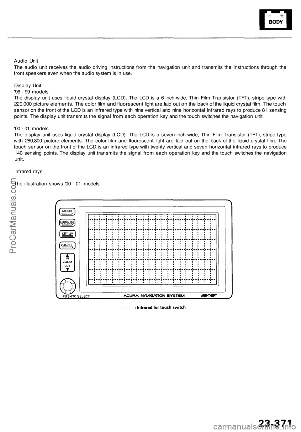
Th e displa y uni t use s liqui d crysta l displa y (LCD) . Th e LC D is a seven-inch-wide , Thi n Fil m Transisto r (TFT) , strip e typ e
wit h 280,80 0 pictur e elements . Th e colo r fil m an d fluorescen t ligh t ar e lai d ou t o n th e bac k o f th e liqui d crysta l film . Th e
touc h senso r o n th e fron t o f th e LC D is a n infrare d typ e wit h twent y vertica l an d seve n horizonta l infrare d ray s t o produc e
14 0 sensin g points . Th e displa y uni t transmit s th e signa l fro m eac h operatio n ke y an d th e touc h switche s th e navigatio n
unit.
Infrare d ray s
The illustratio n show s '0 0 - 0 1 models .
ProCarManuals.com
Page 1735 of 1954
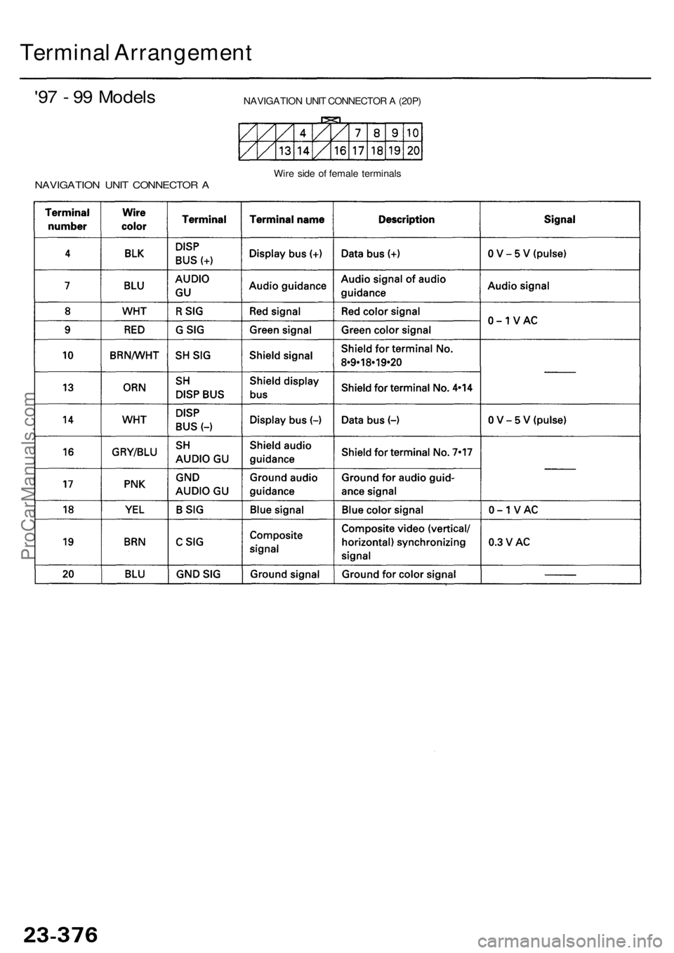
Terminal Arrangemen t
'97 - 9 9 Model s
NAVIGATIO N UNI T CONNECTO R A
NAVIGATIO N UNI T CONNECTO R A (20P )
Wir e sid e o f femal e terminal s
ProCarManuals.com
Page 1736 of 1954
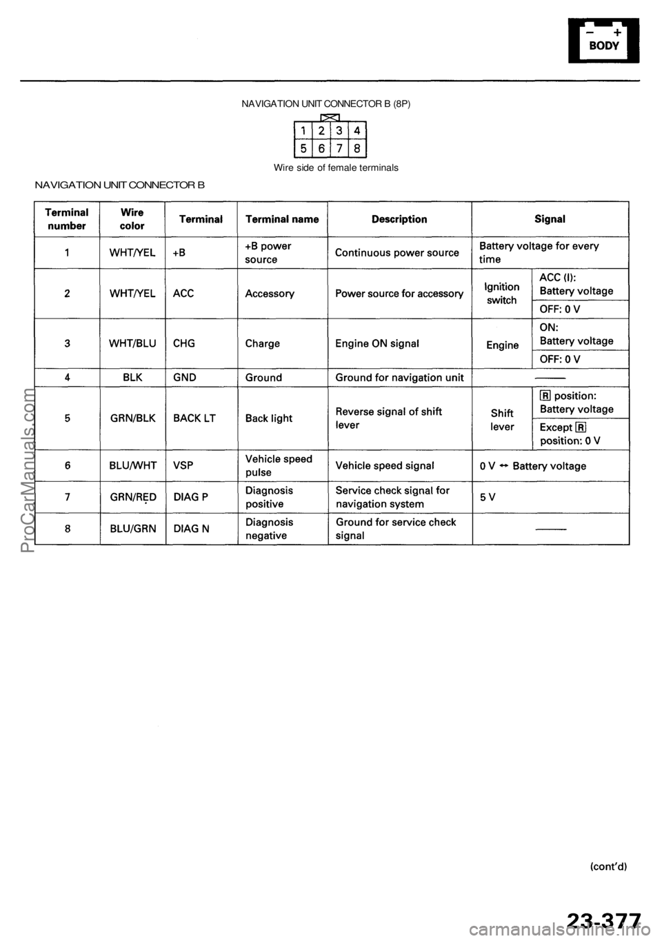
NAVIGATION UNI T CONNECTO R B (8P )
NAVIGATIO N UNI T CONNECTO R B
Wir e sid e o f femal e terminal s
ProCarManuals.com
Page 1737 of 1954
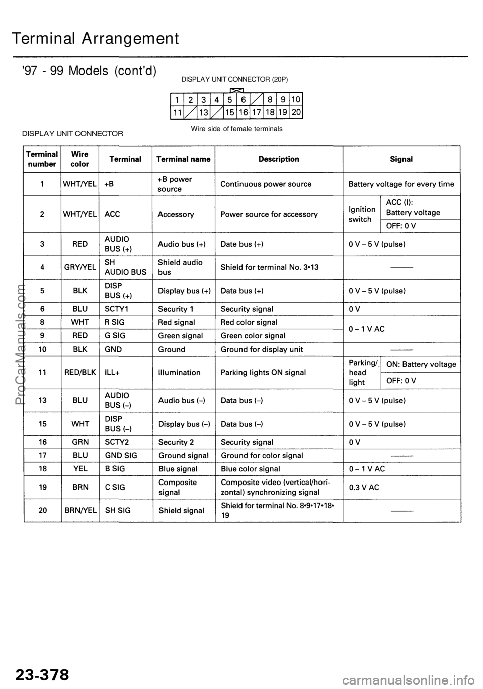
Terminal Arrangemen t
'97 - 9 9 Model s (cont'd )
DISPLAY UNI T CONNECTO R
DISPLAY UNI T CONNECTO R (20P )
Wir e sid e o f femal e terminal s
ProCarManuals.com
Page 1738 of 1954
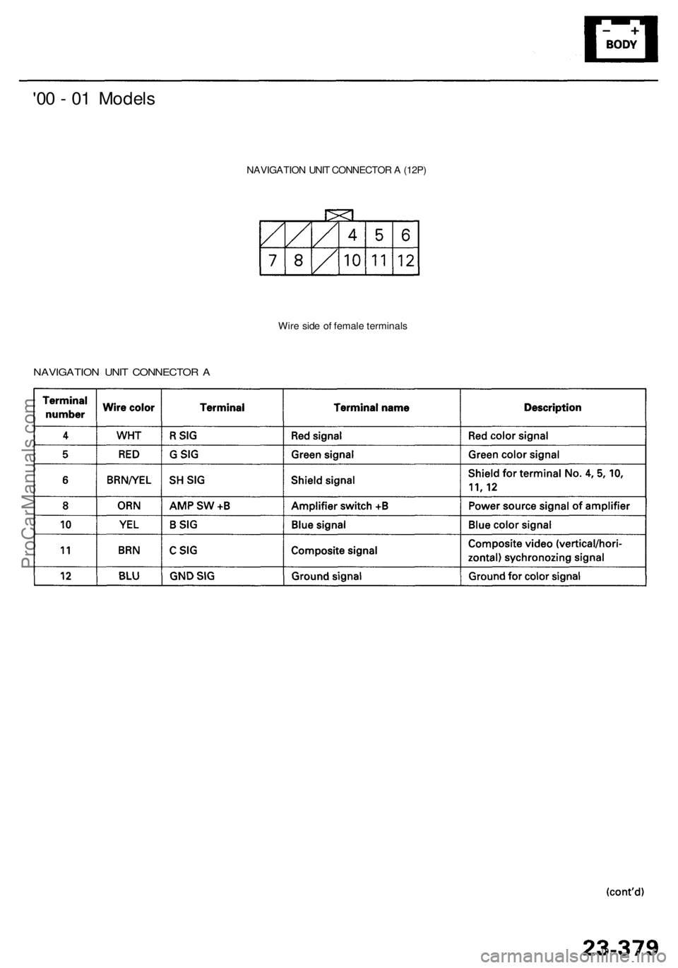
'00 - 0 1 Model s
NAVIGATIO N UNI T CONNECTO R A (12P )
NAVIGATIO N UNI T CONNECTO R A
Wir e sid e o f femal e terminal s
ProCarManuals.com
Page 1739 of 1954
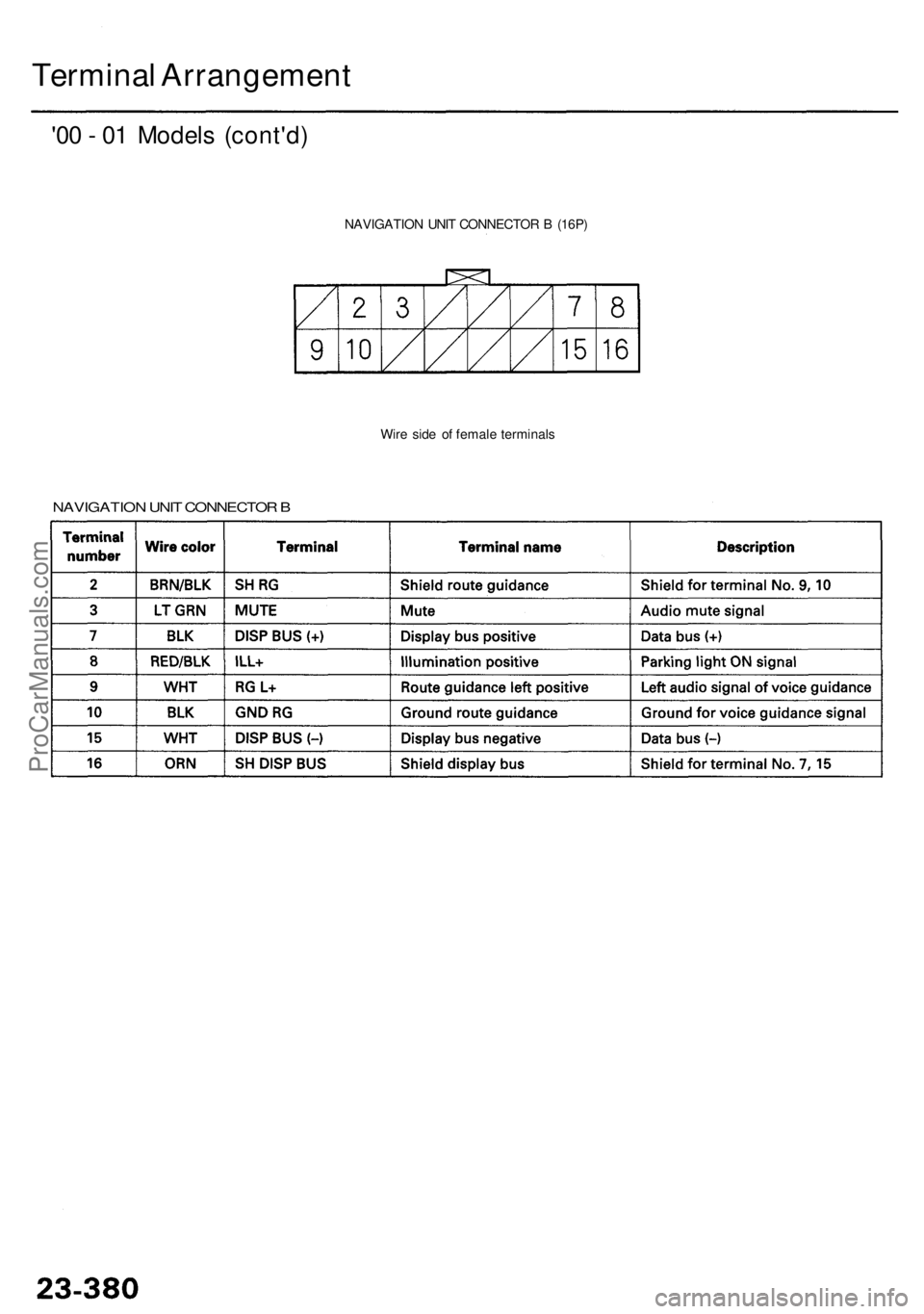
Terminal Arrangemen t
'00 - 0 1 Model s (cont'd )
NAVIGATIO N UNI T CONNECTO R B (16P )
Wir e sid e o f femal e terminal s
NAVIGATIO N UNI T CONNECTO R B
ProCarManuals.com
Page 1740 of 1954
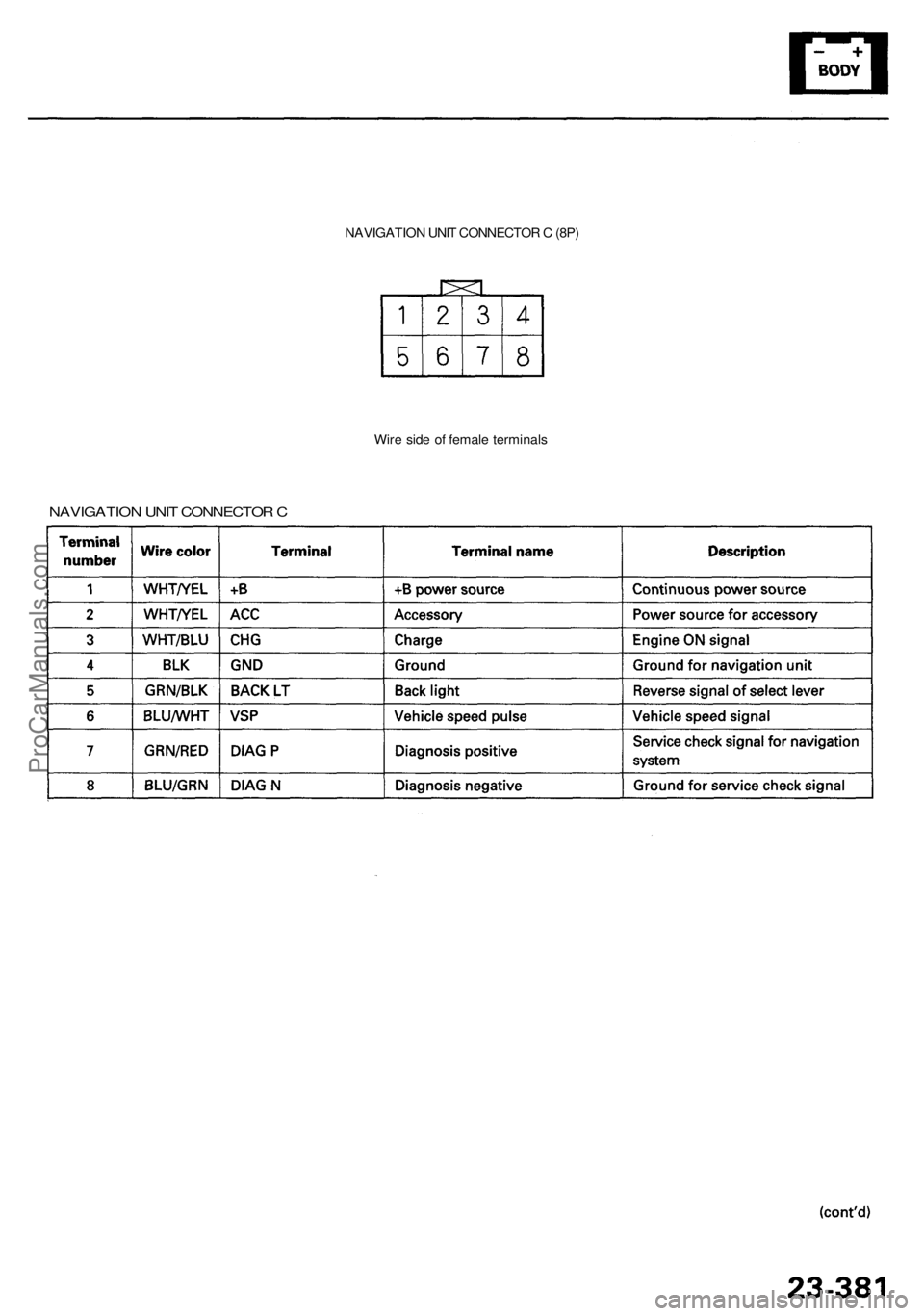
NAVIGATION UNI T CONNECTO R C (8P )
Wir e sid e o f femal e terminal s
NAVIGATIO N UNI T CONNECTO R C
ProCarManuals.com