fuse box ACURA RL KA9 1996 Service User Guide
[x] Cancel search | Manufacturer: ACURA, Model Year: 1996, Model line: RL KA9, Model: ACURA RL KA9 1996Pages: 1954, PDF Size: 61.44 MB
Page 175 of 1954
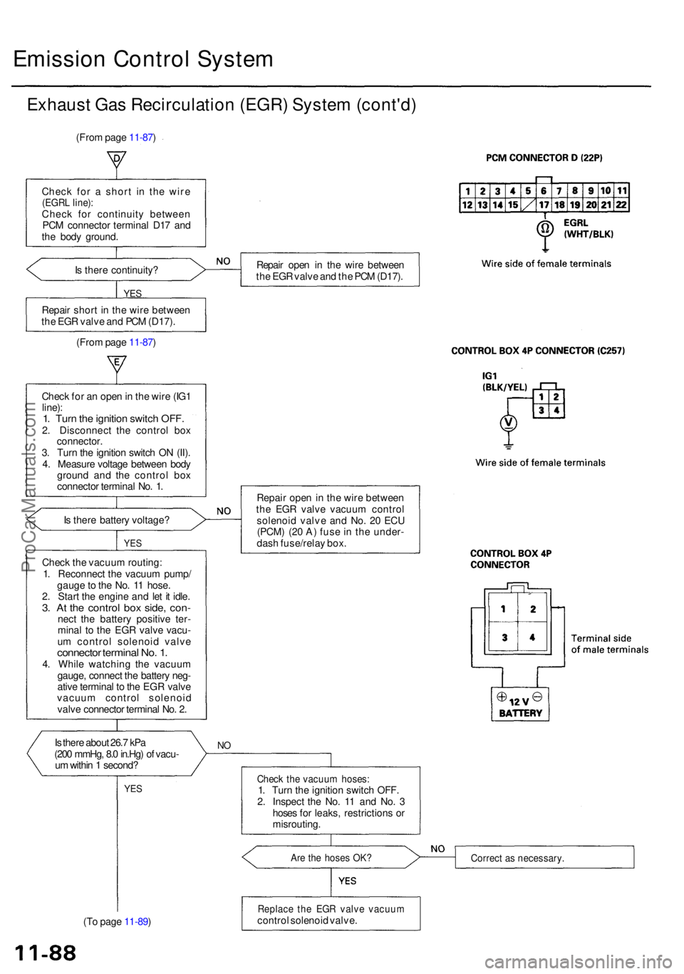
Emission Contro l Syste m
Exhaus t Ga s Recirculatio n (EGR ) Syste m (cont'd )
(From pag e 11-87 )
Chec k fo r a shor t i n th e wir e
(EGR L line) :Chec k fo r continuit y betwee n
PC M connecto r termina l D1 7 an d
th e bod y ground .
I s ther e continuity ?
YES
Repai r shor t i n th e wir e betwee n
th e EG R valv e an d PC M (D17) .
(Fro m pag e 11-87 ) Repai
r ope n i n th e wir e betwee n
th e EG R valv e an d th e PC M (D17) .
Chec k fo r a n ope n in th e wir e (IG 1
line) :1. Tur n th e ignitio n switc h OFF .2. Disconnec t th e contro l bo x
connector .
3 . Tur n th e ignitio n switc h O N (II) .
4 . Measur e voltag e betwee n bod y
groun d an d th e contro l bo x
connecto r termina l No . 1 .
I s ther e batter y voltage ?
YES
Chec k th e vacuu m routing :
1 . Reconnec t th e vacuu m pump /
gaug e to th e No . 1 1 hose .
2 . Star t th e engin e an d le t i t idle .
3. A t th e contro l bo x side , con -nect th e batter y positiv e ter -
mina l t o th e EG R valv e vacu -
u m contro l solenoi d valv e
connecto r termina l No . 1 .4. Whil e watchin g th e vacuu m
gauge , connec t th e batter y neg -
ativ e termina l t o th e EG R valv e
vacuu m contro l solenoi d
valv e connecto r termina l No . 2 .
I s ther e abou t 26. 7 kP a
(20 0 mmHg , 8. 0 in.Hg ) o f vacu -
u m withi n 1 second ?
YES
(To pag e 11-89 )
NO
Repai r ope n in th e wir e betwee n
th e EG R valv e vacuu m contro l
solenoi d valv e an d No . 2 0 EC U
(PCM ) (2 0 A ) fus e in th e under -
das h fuse/rela y box .
Chec k th e vacuu m hoses :1. Tur n th e ignitio n switc h OFF .
2 . Inspec t th e No . 1 1 an d No . 3
hose s fo r leaks , restriction s o r
misrouting .
Are th e hose s OK ?Correc t a s necessary .
Replace th e EG R valv e vacuu mcontrol solenoi d valve .
ProCarManuals.com
Page 195 of 1954
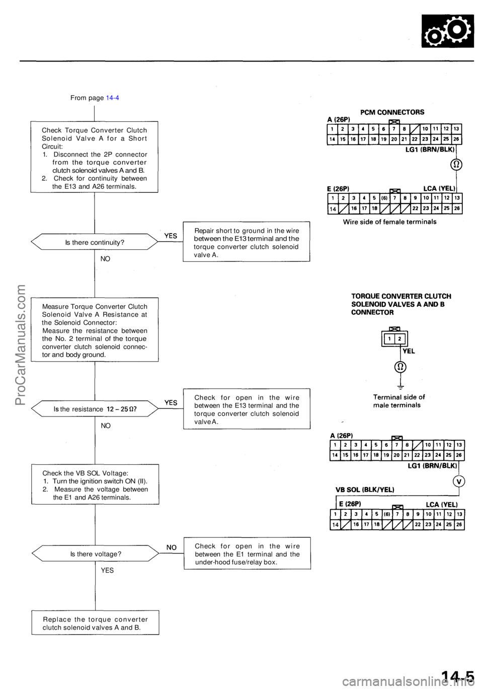
From pag e 14-4
Chec k Torqu e Converte r Clutc h
Solenoi d Valv e A fo r a Shor t
Circuit :
1 . Disconnec t th e 2 P connecto r
from th e torqu e converte rclutch solenoi d valve s A an d B .2. Chec k fo r continuit y betwee n
th e E1 3 an d A2 6 terminals .
Is ther e continuity ?
NO
Repai r shor t t o groun d in th e wir ebetwee n th e E1 3 termina l an d th etorqu e converte r clutc h solenoi dvalve A .
Measur e Torqu e Converte r Clutc h
Solenoi d Valv e A Resistanc e a t
th e Solenoi d Connector :
Measur e th e resistanc e betwee n
the No . 2 termina l o f th e torqu econverte r clutc h solenoi d connec -tor an d bod y ground .
Is th e resistanc e 12-25
NO
Chec k fo r ope n i n th e wir e
betwee n th e E1 3 termina l an d th e
torqu e converte r clutc h solenoi d
valv e A .
I s ther e voltage ?
YES
Chec k fo r ope n i n th e wir e
betwee n th e E 1 termina l an d th e
under-hoo d fuse/rela y box .
Replac e th e torqu e converte r
clutc h solenoi d valve s A an d B .
Chec
k th e V B SO L Voltage :
1. Tur n th e ignitio n switc h O N (II) .2. Measur e th e voltag e betwee n
th e E 1 an d A2 6 terminals .
ProCarManuals.com
Page 197 of 1954
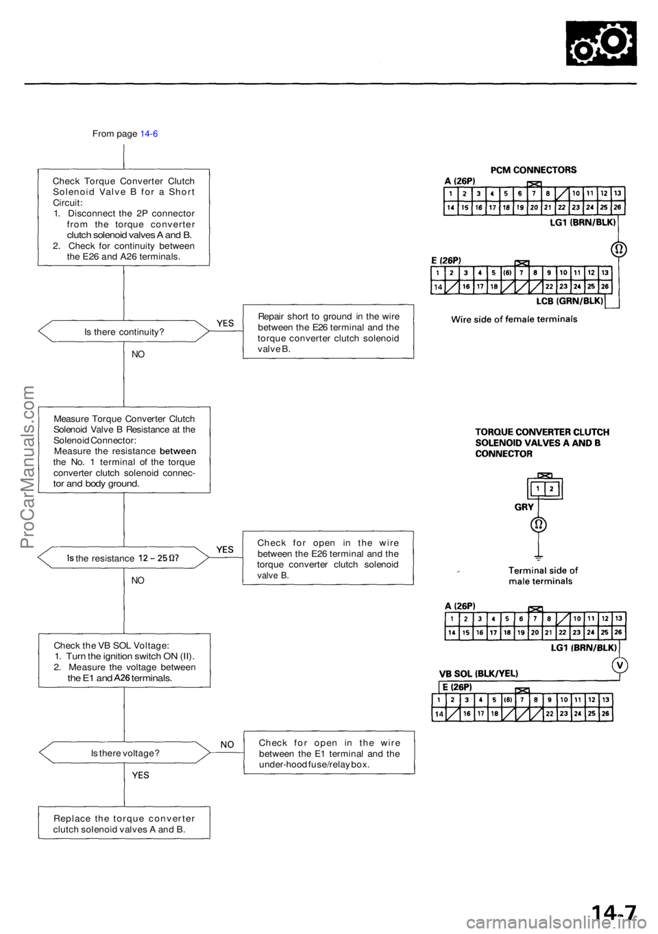
From pag e 14-6
Chec k Torqu e Converte r Clutc h
Solenoi d Valv e B fo r a Shor t
Circuit :
1 . Disconnec t th e 2 P connecto r
fro m th e torqu e converte r
clutch solenoi d valve s A an d B .2. Chec k fo r continuit y betwee n
th e E2 6 an d A2 6 terminals .
I s ther e continuity ?
NO
Repai r shor t t o groun d in th e wir e
betwee n th e E2 6 termina l an d th e
torqu e converte r clutc h solenoi d
valv e B .
Measur e Torqu e Converte r Clutc h
Solenoi d Valv e B Resistanc e a t th e
Solenoi d Connector :
Measure th e resistanc e betweenthe No . 1 termina l o f th e torqu e
converte r clutc h solenoi d connec -
tor an d bod y ground .
Is th e resistanc e 12-25
NO
Chec k fo r ope n i n th e wir e
betwee n th e E2 6 termina l an d th e
torqu e converte r clutc h solenoi d
valve B .
Is ther e voltage ? Chec
k fo r ope n i n th e wir e
betwee n th e E 1 termina l an d th e
under-hoo d fuse/rela y box .
Chec
k th e V B SO L Voltage :
1. Tur n th e ignitio n switc h O N (II) .2. Measur e th e voltag e betwee nthe E 1 an d A2 6 terminals .
Replace th e torqu e converte r
clutc h solenoi d valve s A an d B .
ProCarManuals.com
Page 204 of 1954
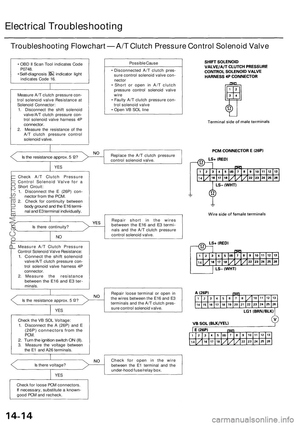
Electrical Troubleshooting
Troubleshooting Flowchart — A/T Clutch Pressure Control Solenoid Valve
• OBD II Scan Tool indicates Code
P0748.
• Self-diagnosis indicator light
indicates Code 16.
Measure A/T clutch pressure con-
trol solenoid valve Resistance at
Solenoid Connector:
1. Disconnect the shift solenoid
valve/A/T clutch pressure con-
trol solenoid valve harness 4P
connector.
2. Measure the resistance of the
A/T clutch pressure control
solenoid valve.
Is the resistance approx. 5 ?
YES
Check A/T Clutch Pressure
Control Solenoid Valve for a
Short Circuit:
1. Disconnect the E (26P) con-
nector from the PCM.
2. Check for continuity between
body ground and the E16 termi-
nal and E3 terminal individually.
Is there continuity?
NO
Measure A/T Clutch Pressure
Control Solenoid Valve Resistance:
1. Connect the shift solenoid
valve/A/T clutch pressure con-
trol solenoid valve harness 4P
connector.
2. Measure the resistance
between the E16 and E3 ter-
minals.
Is the resistance approx. 5 ?
YES
Check the VB SOL Voltage:
1. Disconnect the A (26P) and E
(26P) connectors from the
PCM.
2. Turn the ignition switch ON (II).
3. Measure the voltage between
the E1 and A26 terminals.
Is there voltage?
YES
Check for loose PCM connectors.
If necessary, substitute a known-
good PCM and recheck.
Possible Cause
• Disconnected A/T clutch pres-
sure control solenoid valve con-
nector
• Short or open in A/T clutch
pressure control solenoid valve
wire
• Faulty A/T clutch pressure con-
trol solenoid valve
• Open VB SOL line
Replace the A/T clutch pressure
control solenoid valve.
Repair short in the wires
between the E16 and E3 termi-
nals and the A/T clutch pressure
control solenoid valve.
Repair loose terminal or open in
the wires between the E16 and E3
terminals and the A/T clutch pres-
sure control solenoid valve.
Check for open in the wire
between the E1 terminal and the
under-hood fuse/relay box.ProCarManuals.com
Page 223 of 1954
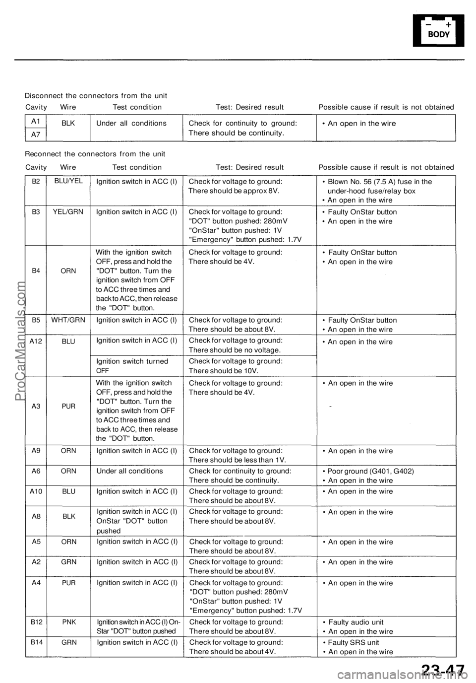
Disconnect the connectors from the unit
Cavity Wire Test condition
Test: Desired result
Possible cause if result is not obtained
A1
A7
BLK
Under all conditions
Check for continuity to ground:
There should be continuity.
• An open in the wire
Reconnect the connectors from the unit
Cavity Wire Test condition
Test: Desired result
Possible cause if result is not obtained
B2
B3
B4
B5
A12
A3
A9
A6
A10
A8
A5
A2
A4
B12
B14
BLU/YEL
YEL/GRN
ORN
WHT/GRN
BLU
PUR
ORN
ORN
BLU
BLK
ORN
GRN
PUR
PNK
GRN
Ignition switch in ACC (I)
Ignition switch in ACC (I)
With the ignition switch
OFF, press and hold the
"DOT" button. Turn the
ignition switch from OFF
to ACC three times and
back to ACC, then release
the "DOT" button.
Ignition switch in ACC (I)
Ignition switch in ACC (I)
Ignition switch turned
OFF
With the ignition switch
OFF, press and hold the
"DOT" button. Turn the
ignition switch from OFF
to ACC three times and
back to ACC, then release
the "DOT" button.
Ignition switch in ACC (I)
Under all conditions
Ignition switch in ACC (I)
Ignition switch in ACC (I)
OnStar "DOT" button
pushed
Ignition switch in ACC (I)
Ignition switch in ACC (I)
Ignition switch in ACC (I)
Ignition switch in ACC (I) On-
Star "DOT" button pushed
Ignition switch in ACC (I)
Check for voltage to ground:
There should be approx 8V.
Check for voltage to ground:
"DOT" button pushed: 280mV
"OnStar" button pushed: 1V
"Emergency" button pushed: 1.7V
Check for voltage to ground:
There should be 4V.
Check for voltage to ground:
There should be about 8V.
Check for voltage to ground:
There should be no voltage.
Check for voltage to ground:
There should be 10V.
Check for voltage to ground:
There should be 4V.
Check for voltage to ground:
There should be less than 1V.
Check for continuity to ground:
There should be continuity.
Check for voltage to ground:
There should be about 8V.
Check for voltage to ground:
There should be about 8V.
Check for voltage to ground:
There should be about 8V.
Check for voltage to ground:
There should be about 8V.
Check for voltage to ground:
"DOT" button pushed: 280mV
"OnStar" button pushed: 1V
"Emergency" button pushed: 1.7V
Check for voltage to ground:
There should be about 8V.
Check for voltage to ground:
There should be about 4V.
• Blown No. 56 (7.5 A) fuse in the
under-hood fuse/relay box
• An open in the wire
• Faulty OnStar button
• An open in the wire
• Faulty OnStar button
• An open in the wire
• Faulty OnStar button
• An open in the wire
• An open in the wire
• An open in the wire
• An open in the wire
• Poor ground (G401, G402)
• An open in the wire
• An open in the wire
• An open in the wire
• An open in the wire
• An open in the wire
• An open in the wire
• Faulty audio unit
• An open in the wire
• Faulty SRS unit
• An open in the wireProCarManuals.com
Page 249 of 1954
Symptom Troubleshootin g
No pictur e is displaye d
Diagnosti c Test : Navigatio n Syste m Lin k
1 . Chec k th e No . 5 6 (7.5A ) fus e in th e under-hoo d fuse /
rela y bo x an d No . 4 (10A ) fus e in th e under-das h fuse /
relay box , an d reinstal l th e fuse s i f the y are-OK .
Are the fuses OK?
YES—G o to ste p 2 .
NO—Replac e th e fus e an d recheck .
2 . Tur n th e ignitio n switc h t o AC C (I) .
3 . Operat e th e radi o an d liste n t o th e audio .
Can audio be heard?
YES—G o to ste p 4 .
NO—Chec k th e AC C circuit .
4 . Tur n th e ignitio n switc h O N (II) .
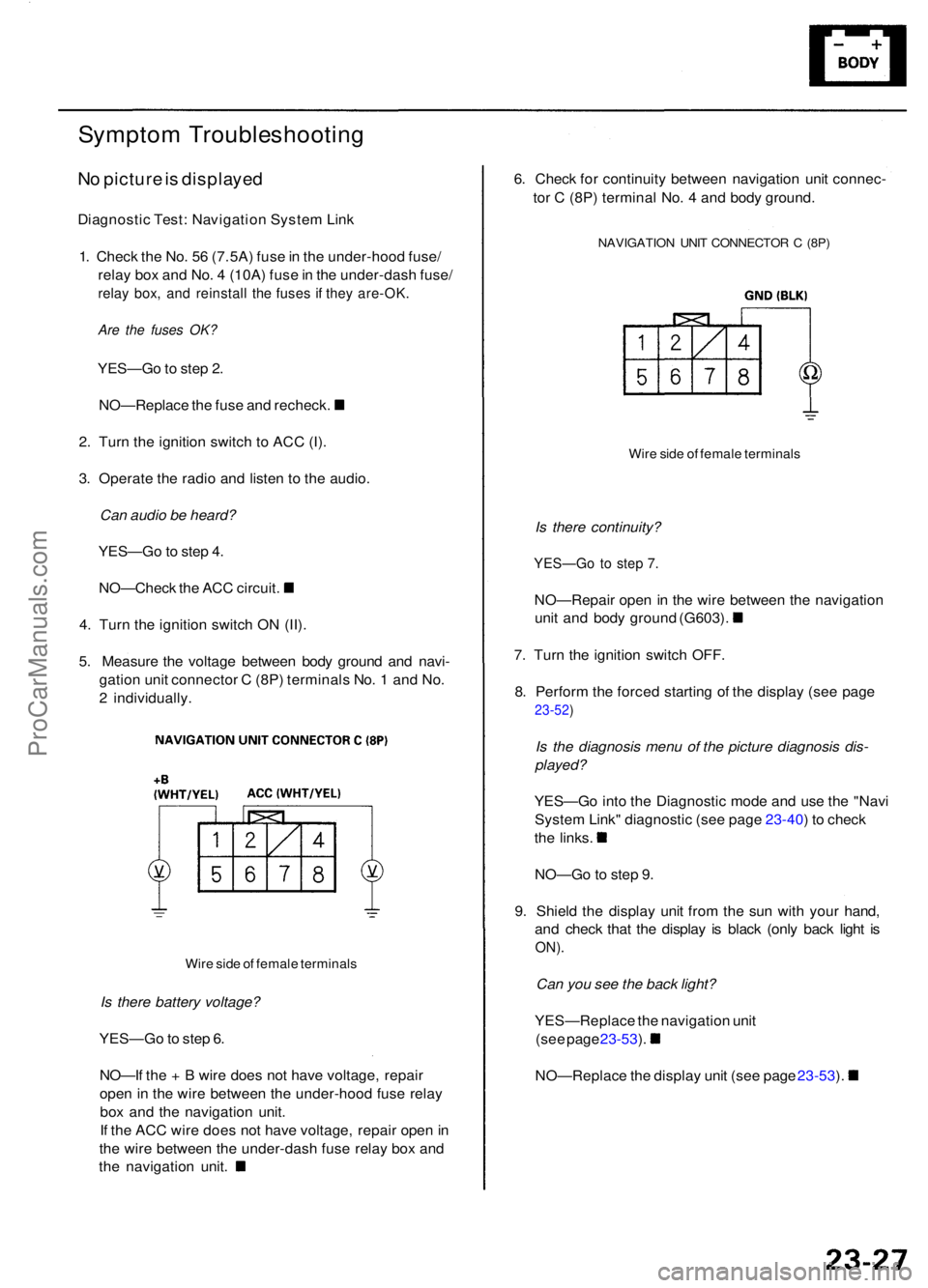
5 . Measur e th e voltag e betwee n bod y groun d an d navi -
gatio n uni t connecto r C (8P ) terminal s No . 1 an d No .
2 individually .
Wire sid e o f femal e terminal s
Is there battery voltage?
YES—G o to ste p 6 .
NO—I f th e + B wir e doe s no t hav e voltage , repai r
ope n in th e wir e betwee n th e under-hoo d fus e rela y
bo x an d th e navigatio n unit .
I f th e AC C wir e doe s no t hav e voltage , repai r ope n in
th e wir e betwee n th e under-das h fus e rela y bo x an d
th e navigatio n unit . 6
. Chec k fo r continuit y betwee n navigatio n uni t connec -
to r C (8P ) termina l No . 4 an d bod y ground .
NAVIGATIO N UNI T CONNECTO R C (8P )
Wire sid e o f femal e terminal s
Is there continuity?
YES—G o to ste p 7 .
NO—Repai r ope n i n th e wir e betwee n th e navigatio n
unit an d bod y groun d (G603) .
7 . Tur n th e ignitio n switc h OFF .
8 . Perfor m th e force d startin g o f th e displa y (se e pag e
23-52 )
Is the diagnosis menu of the picture diagnosis dis-
played?
YES—G o int o th e Diagnosti c mod e an d us e th e "Nav i
Syste m Link " diagnosti c (se e pag e 23-40 ) t o chec k
the links .
NO—G o to ste p 9 .
9 . Shiel d th e displa y uni t fro m th e su n wit h you r hand ,
an d chec k tha t th e displa y i s blac k (onl y bac k ligh t i s
ON) .
Can you see the back light?
YES—Replac e th e navigatio n uni t
(see pag e 23-53 ).
NO—Replac e th e displa y uni t (se e pag e 23-53 ).
ProCarManuals.com
Page 254 of 1954
Navigation Syste m
Sympto m Troubleshootin g (cont'd )
Display uni t button s d o no t wor k
NOTE :
• Alway s chec k th e connector s fo r poo r connection s o r
loos e terminals .
• Befor e troubleshooting , ge t th e navigatio n syste m
anti-thef t codes .
• Afte r troubleshooting , ente r th e navigatio n syste m
anti-thef t codes .
1. Tur n th e ignitio n switc h to AC C (I) .
2. G o int o th e Diagnosti c mod e an d us e "Touc h Panel "
diagnosti c unde r Monito r Chec k (se e pag e 23-41 )
and, i f necessary , "Display " diagnosti c unde r Uni t
Chec k (se e pag e 23-43 ).
Do the buttons work properly?
YES—System is OK .
NO—G o t o ste p 3 .
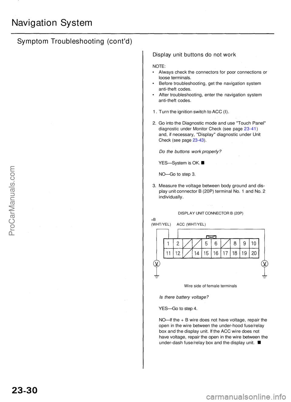
3. Measur e th e voltag e betwee n bod y groun d an d dis -
play uni t connecto r B (20P ) termina l No . 1 an d No . 2
individually .
DISPLAY UNI T CONNECTO R B (20P )
+B(WHT/YEL ) AC C (WHT/YEL )
Wire sid e o f femal e terminal s
Is there battery voltage?
YES—G o to ste p 4 .
NO—I f th e + B wir e doe s no t hav e voltage , repai r th e
ope n in th e wir e betwee n th e under-hoo d fuse/rela y
box an d th e displa y unit . I f th e AC C wir e doe s no t
hav e voltage , repai r th e ope n in th e wir e betwee n th e
under-das h fuse/rela y bo x an d th e displa y unit .
ProCarManuals.com
Page 344 of 1954
Troubleshooting
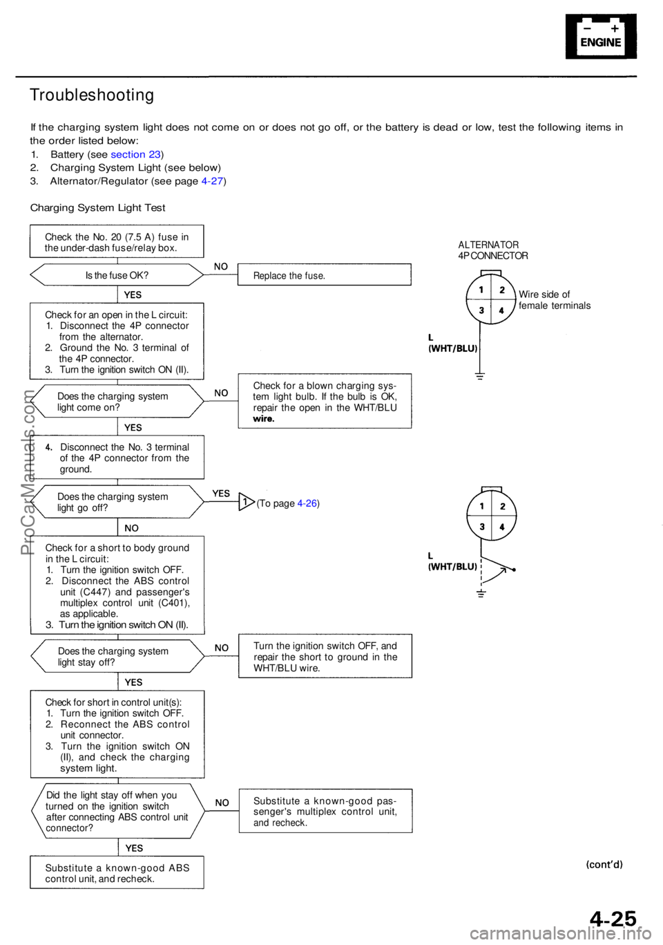
If th e chargin g syste m ligh t doe s no t com e o n o r doe s no t g o off , o r th e batter y i s dea d o r low , tes t th e followin g item s i n
th e orde r liste d below :
1. Batter y (se e sectio n 23 )
2. Chargin g Syste m Ligh t (se e below )
3. Alternator/Regulato r (se e pag e 4-27 )
Chargin g Syste m Ligh t Tes t
Chec k th e No . 2 0 (7. 5 A ) fus e i n
th e under-das h fuse/rela y box .
I s th e fus e OK ?
Chec k fo r a n ope n in th e L circuit :
1 . Disconnec t th e 4 P connecto r
fro m th e alternator .
2 . Groun d th e No . 3 termina l o f
th e 4 P connector .
3 . Tur n th e ignitio n switc h O N (II) .
Doe s th e chargin g syste m
ligh t com e on ?
Disconnec t th e No . 3 termina l
o f th e 4 P connecto r fro m th e
ground .
Doe s th e chargin g syste m
ligh t g o off ?
Chec k fo r a shor t t o bod y groun d
i n th e L circuit :
1 . Tur n th e ignitio n switc h OFF .
2 . Disconnec t th e AB S contro l
uni t (C447 ) an d passenger' s
multiple x contro l uni t (C401) ,
a s applicable .
3. Tur n th e ignitio n switc h O N (II) .
Doe s th e chargin g syste m
ligh t sta y off ?
Chec k fo r shor t i n contro l unit(s) :
1 . Tur n th e ignitio n switc h OFF .
2 . Reconnec t th e AB S contro l
uni t connector .
3 . Tur n th e ignitio n switc h O N
(II) , an d chec k th e chargin g
system light .
Did th e ligh t sta y of f whe n yo u
turne d o n th e ignitio n switc h
afte r connectin g AB S contro l uni t
connector ?
Substitute a known-goo d AB S
contro l unit , an d recheck .
ALTERNATO R4P CONNECTO R
Replace th e fuse .
Chec k fo r a blow n chargin g sys -
te m ligh t bulb . I f th e bul b i s OK ,
repai r th e ope n i n th e WHT/BL U Wir
e sid e o f
femal e terminal s
(T o page 4-26)
Tur n th e ignitio n switc h OFF , an d
repai r th e shor t t o groun d in th e
WHT/BL U wire .
Substitut e a known-goo d pas -
senger' s multiple x contro l unit ,
and recheck .
ProCarManuals.com
Page 356 of 1954

Cruise Control
Control Unit Input Test (cont'd)
Cavity Wire
Test condition
Test: Desired result
Possible cause if result is not obtained
3
13
7
6
14
12
2
5
10
9
11
1
BLK
LT GRN
LT GRN/BLK
LT GRN/RED
PNK
BLU/WHT
GRY
GRN/WHT
BLU/YEL
BRN
BRN/BLK
BRN/WHT
Under all conditions
Ignition switch ON (II) and
main switch ON
Resume button pushed
Cancel button pushed
Set button pushed
Cancel button pushed
Shift lever in , or
Ignition switch ON (II), and
main switch ON; raise the
front of the vehicle, and rotate
one wheel slowly while
holding the other wheel.
Ignition switch ON (II), main
switch ON; brake pedal
pressed, then released
Brake pedal pressed then
released
Ignition switch ON (II)
Under all conditions
Under all conditions
Under all conditions
Check for continuity to ground:
There should be continuity.
Check for voltage to ground:
There should be battery voltage.
Check for voltage to ground:
There should be battery voltage.
When testing terminal No. 7, there
should be no voltage on terminal No. 6.
Check for voltage to ground:
There should be battery voltage.
When testing terminal No. 7, there
should be voltage on terminal No. 6.
Check for voltage to ground:
There should be battery voltage.
When testing terminal No. 6, there
should be no voltage on terminal No. 7.
Check for voltage to ground:
There should be battery voltage.
When testing terminal No. 6, there
should be voltage on terminal No. 7.
Check for continuity to ground:
There should be continuity.
NOTE: There should be no continuity
when the shift lever is in other positions.
Check for voltage between the
BLU/ WHT and BLK terminals:
There should be cycle 0 - 5 V or
battery voltage.
Check for voltage to ground:
There should be 0 V with the pedal
pressed, and battery voltage with
the pedal released.
Check for voltage to ground:
There should be battery voltage with
the pedal pressed, and 0 V with the
pedal released.
Attach to ground:
The cruise light in the gauge assembly
should come on.
Check for resistance to ground:
There should be 80 -120
Check for resistance to ground:
There should be 70 -110
Check for resistance to ground:
There should be 40 - 60
• Poor ground (G401, G402)
• An open in the wire
• Blown No. 20 (20 A) fuse in the
under-dash fuse/relay box
• Faulty main switch
• An open in the wire
• Blown No. 39 (15 A) fuse in the
under-hood fuse/relay box
• Faulty horn relay
• Faulty set/resume/cancel switch
• Faulty cable reel
• An open in the wire
• Short between LT GRN/BLK and
LT GRN/RED wires
• Blown No. 39 (15 A) fuse in the
under-hood fuse/relay box
• Faulty horn relay
• Faulty set/resume/cancel switch
• Faulty cable reel
• An open in the wire
• Blown No. 39 (15 A) fuse in the
under-hood fuse/relay box
• Faulty horn relay
• Faulty set/resume/cancel switch
• Faulty cable reel
• An open in the wire
• Short between LT GRN/BLK and
LT GRN/RED wires
• Blown No. 39 (15 A) fuse in the
under-hood fuse/relay box
• Faulty horn relay
• Faulty set/resume/cancel switch
• Faulty cable reel
• An open in the wire
• Faulty A/T gear position switch
• Poor ground (G401, G402)
• An open in the wire
• Faulty vehicle speed sensor (VSS)
• An open in the wire
• Short to ground
• Blown No. 39 (15 A) fuse in the
under-hood fuse/relay box
• Faulty brake switch
• An open in the wire
• Blown No. 39 (15 A) fuse in the
under-hood fuse/relay box
• Faulty brake switch
• An open in the wire
• Blown bulb
• Faulty gauge circuit
• An open in the wire
• Faulty actuator solenoid
• An open in the wireProCarManuals.com
Page 367 of 1954
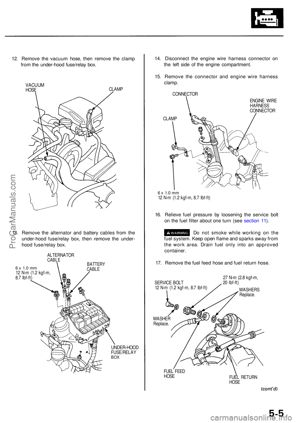
12. Remov e th e vacuu m hose , the n remov e th e clam p
fro m th e under-hoo d fuse/rela y box .
VACUU MHOSE CLAM
P
13. Remov e th e alternato r an d batter y cable s fro m th e
under-hoo d fuse/rela y box , the n remov e th e under -
hoo d fuse/rela y box .
ALTERNATO RCABLE
6 x 1. 0 m m12 N- m (1. 2 kgf-m ,
8. 7 Ibf-ft )
BATTER YCABLE
UNDER-HOO DFUSE/RELAYBOX
14. Disconnec t th e engin e wir e harnes s connecto r o n
th e lef t sid e o f th e engin e compartment .
15 . Remov e th e connecto r an d engin e wir e harnes s
clamp .
CONNECTO R
ENGINE WIR E
HARNES S
CONNECTO R
CLAMP
6 x 1. 0 m m12 N- m (1. 2 kgf-m , 8. 7 Ibf-ft )
16. Reliev e fue l pressur e b y loosenin g th e servic e bol t
o n th e fue l filte r abou t on e tur n (se e sectio n 11 ).
D o no t smok e whil e workin g o n th e
fue l system . Kee p ope n flam e an d spark s awa y fro m
th e wor k area . Drai n fue l onl y int o a n approve d
container.
17. Remov e th e fue l fee d hos e an d fue l retur n hose .
SERVIC E BOL T
1 2 N- m (1. 2 kgf-m , 8. 7 Ibf-ft )
WASHE R
Replace .27 N- m (2. 8 kgf-m ,20 Ibf-ft )
WASHER S
Replace .
FUE L FEE D
HOS E
FUEL RETUR N
HOS E
ProCarManuals.com