fuse box ACURA RL KA9 1996 Service Service Manual
[x] Cancel search | Manufacturer: ACURA, Model Year: 1996, Model line: RL KA9, Model: ACURA RL KA9 1996Pages: 1954, PDF Size: 61.44 MB
Page 684 of 1954
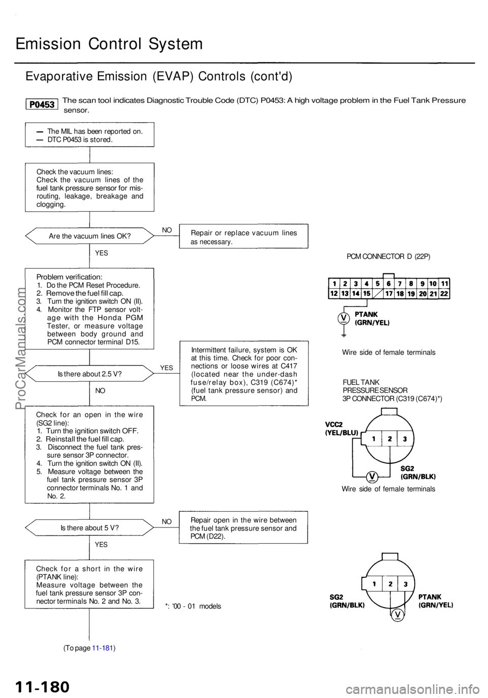
Emission Contro l Syste m
Evaporativ e Emissio n (EVAP ) Control s (cont'd )
The sca n too l indicate s Diagnosti c Troubl e Cod e (DTC ) P0453 : A hig h voltag e proble m in th e Fue l Tan k Pressur e
sensor.
The MI L ha s bee n reporte d on .
DT C P045 3 is stored .
Chec k th e vacuu m lines :
Chec k th e vacuu m line s o f th e
fuel tan k pressur e senso r fo r mis -routing , leakage , breakag e an dclogging .
Are th e vacuu m line s OK ?
YES
Proble m verification :1. D o th e PC M Rese t Procedure .2. Remov e th e fue l fil l cap .3. Tur n th e ignitio n switc h O N (II) .
4 . Monito r th e FT P sensor volt-
age wit h th e Hond a PG MTester , o r measur e voltag e
betwee n bod y groun d an d
PC M connecto r termina l D15 .
I s ther e abou t 2. 5 V ?
NO
Chec k fo r a n ope n i n th e wir e
(SG 2 line) :
1. Tur n th e ignitio n switc h OFF .2. Reinstal l th e fue l fil l cap .3. Disconnec t th e fue l tan k pres -
sur e senso r 3 P connector .
4 . Tur n th e ignitio n switc h O N (II) .
5 . Measur e voltag e betwee n th e
fue l tan k pressur e senso r 3 P
connecto r terminal s No . 1 an d
No. 2 .
Is ther e abou t 5 V ?
YE S
Chec k fo r a shor t i n th e wir e
(PTAN K line) :
Measur e voltag e betwee n th e
fue l tan k pressur e senso r 3 P con -
necto r terminal s No . 2 an d No . 3 .
(T o pag e 11-181 ) Repai
r o r replac e vacuu m line s
as necessary .
PCM CONNECTO R D (22P )
YES
Intermitten t failure , syste m is O K
a t thi s time . Chec k fo r poo r con -
nection s o r loos e wire s a t C41 7
(locate d nea r th e under-das h
fuse/rela y box) , C31 9 (C674) *
(fue l tan k pressur e sensor ) an d
PCM .
Wire sid e o f femal e terminal s
FUE L TAN K
PRESSUR E SENSO R
3 P CONNECTO R (C31 9 (C674)* )
Repai r ope n in th e wir e betwee n
th e fue l tan k pressur e senso r an d
PC M (D22) .
* : '0 0 - 0 1 model s
NO
Wir e sid e o f femal e terminal s
NO
ProCarManuals.com
Page 766 of 1954
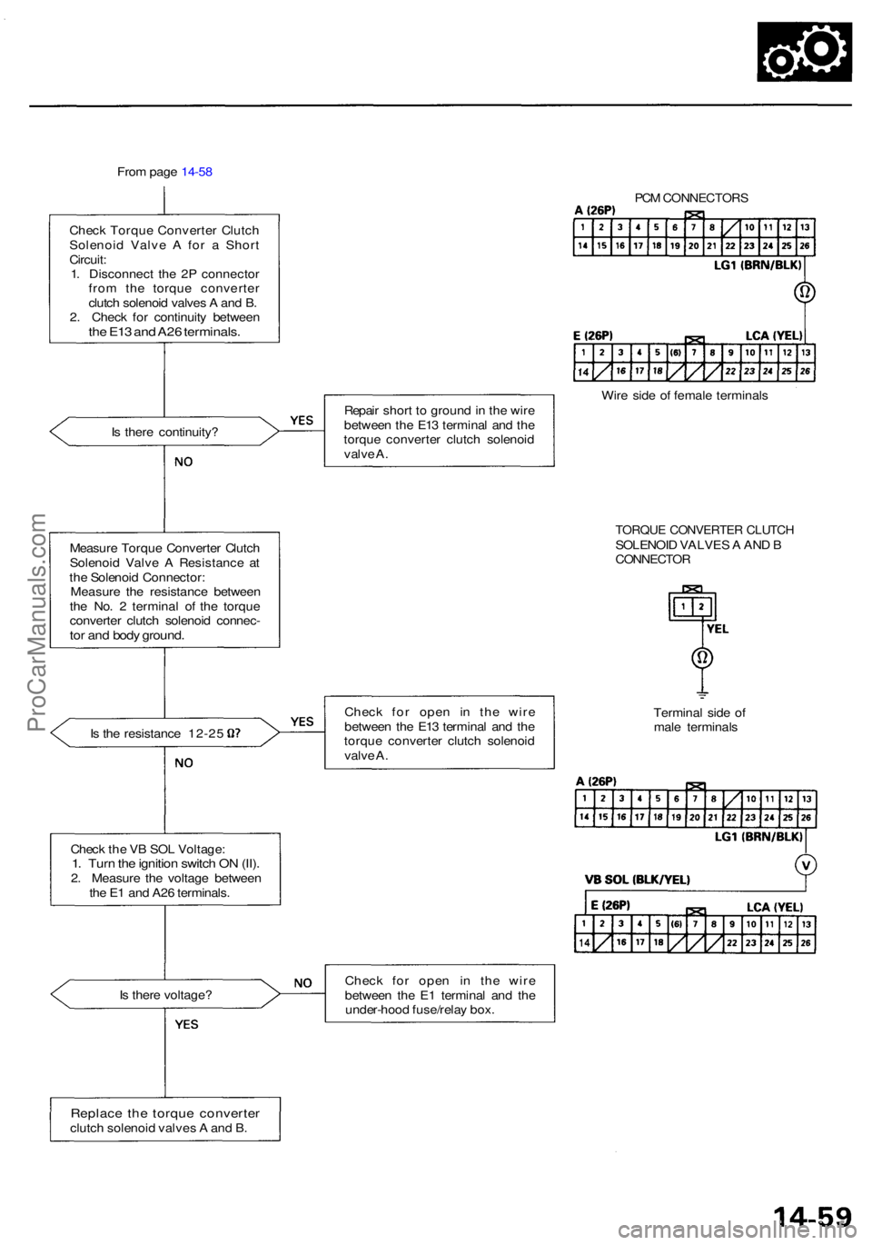
From pag e 14-5 8
Chec k Torqu e Converte r Clutc h
Solenoi d Valv e A fo r a Shor t
Circuit :
1 . Disconnec t th e 2 P connecto r
fro m th e torqu e converte r
clutc h solenoi d valve s A an d B .
2 . Chec k fo r continuit y betwee n
the E1 3 an d A2 6 terminals .
Is ther e continuity ?
Measur e Torqu e Converte r Clutc h
Solenoi d Valv e A Resistanc e a t
th e Solenoi d Connector :
Measur e th e resistanc e betwee n
th e No . 2 termina l o f th e torqu e
converte r clutc h solenoi d connec -
tor an d bod y ground .
Is th e resistanc e 12-2 5
Chec k th e V B SO L Voltage :
1. Tur n th e ignitio n switc h O N (II) .2. Measur e th e voltag e betwee n
th e E 1 an d A2 6 terminals .
I s ther e voltage ?
Replace th e torqu e converte rclutch solenoi d valve s A an d B . Repai
r shor t t o groun d in th e wir e
betwee n th e E1 3 termina l an d th e
torqu e converte r clutc h solenoi d
valv e A .
Chec k fo r ope n i n th e wir e
betwee n th e E1 3 termina l an d th e
torqu e converte r clutc h solenoi d
valv e A .
Chec k fo r ope n i n th e wir e
betwee n th e E 1 termina l an d th e
under-hoo d fuse/rela y box .
PCM CONNECTOR S
Wire sid e o f femal e terminal s
Termina l sid e o f
mal e terminal s
TORQUE CONVERTE R CLUTC HSOLENOI D VALVE S A AN D BCONNECTO R
ProCarManuals.com
Page 768 of 1954
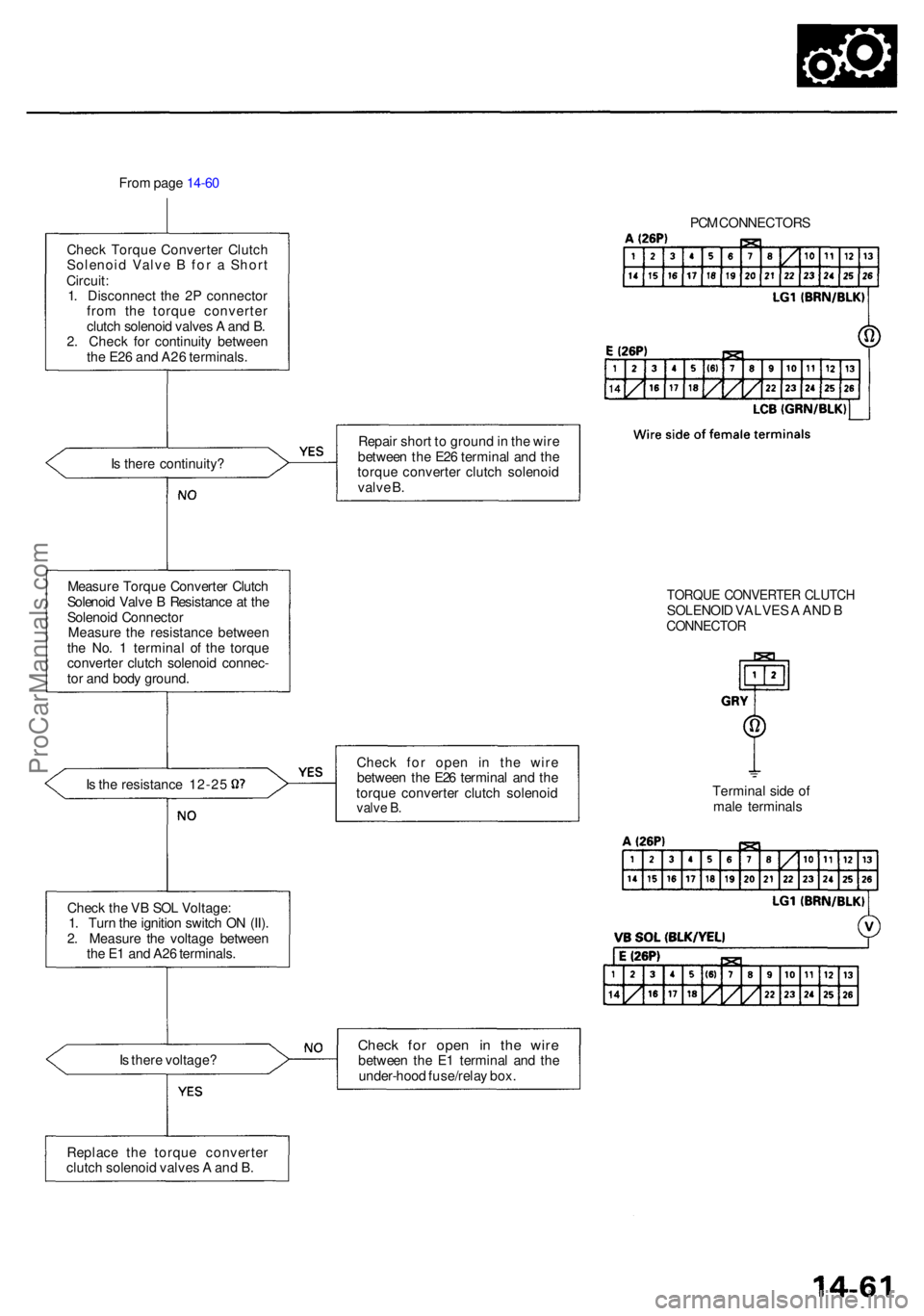
From pag e 14-6 0
Chec k Torqu e Converte r Clutc h
Solenoi d Valv e B fo r a Shor t
Circuit :
1 . Disconnec t th e 2 P connecto r
fro m th e torqu e converte r
clutc h solenoi d valve s A an d B .
2 . Chec k fo r continuit y betwee n
th e E2 6 an d A2 6 terminals .
I s ther e continuity ?
Measur e Torqu e Converte r Clutc h
Solenoi d Valv e B Resistanc e a t th e
Solenoi d Connecto r
Measur e th e resistanc e betwee n
th e No . 1 termina l o f th e torqu e
converte r clutc h solenoi d connec -
to r an d bod y ground .
Is th e resistanc e 12-2 5
Chec k th e V B SO L Voltage :
1 . Tur n th e ignitio n switc h O N (II) .
2 . Measur e th e voltag e betwee n
th e E 1 an d A2 6 terminals .
I s ther e voltage ? PC
M CONNECTOR S
Repai r shor t t o groun d in th e wir e
betwee n th e E2 6 termina l an d th e
torqu e converte r clutc h solenoi d
valv e B .
Chec k fo r ope n i n th e wir e
betwee n th e E2 6 termina l an d th e
torqu e converte r clutc h solenoi d
valve B .
Chec k fo r ope n i n th e wir ebetwee n th e E 1 termina l an d th e
under-hoo d fuse/rela y box .
TORQU E CONVERTE R CLUTC HSOLENOI D VALVE S A AN D BCONNECTO R
Terminal sid e o f
mal e terminal s
Replac e th e torqu e converte r
clutc h solenoi d valve s A an d B .
ProCarManuals.com
Page 776 of 1954
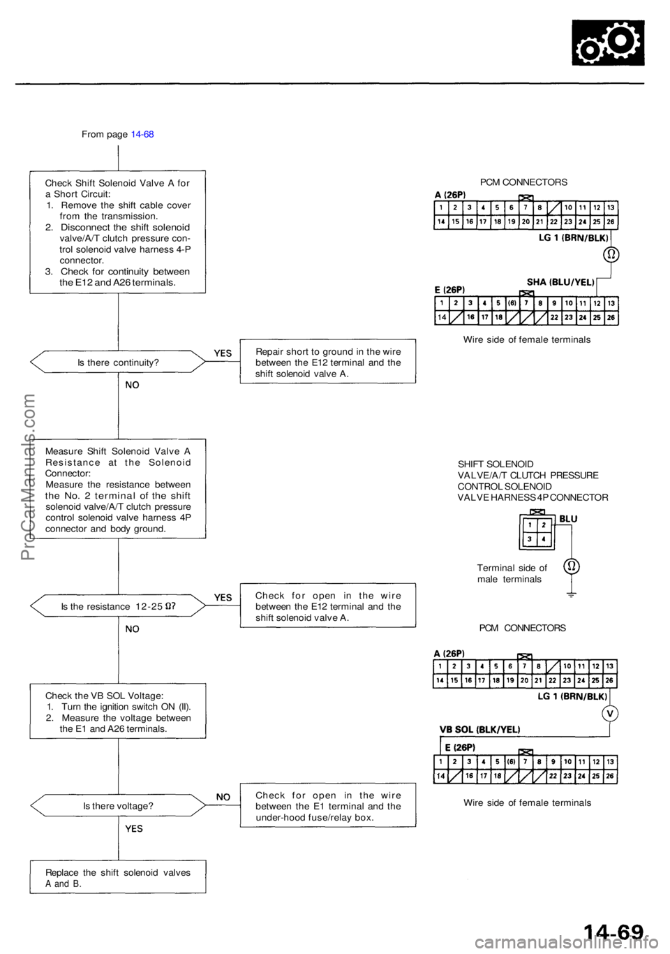
From pag e 14-6 8
Chec k Shif t Solenoi d Valv e A fo r
a Shor t Circuit :
1 . Remov e th e shif t cabl e cove r
fro m th e transmission .
2. Disconnec t th e shif t solenoi dvalve/A/ T clutc h pressur e con -
tro l solenoi d valv e harnes s 4- P
connector .
3. Chec k fo r continuit y betwee nthe E1 2 an d A2 6 terminals .
Is ther e continuity ?
Measur e Shif t Solenoi d Valv e A
Resistanc e a t th e Solenoi d
Connector :
Measur e th e resistanc e betwee n
the No . 2 termina l o f th e shif tsolenoi d valve/A/ T clutc h pressur e
contro l solenoi d valv e harnes s 4 P
connecto r an d bod y ground .
Is th e resistanc e 12-2 5
Chec k th e V B SO L Voltage :
1 . Tur n th e ignitio n switc h O N (II) .
2 . Measur e th e voltag e betwee n
th e E 1 an d A2 6 terminals .
I s ther e voltage ? Repai
r shor t t o groun d in th e wir e
betwee n th e E1 2 termina l an d th e
shif t solenoi d valv e A .
Chec k fo r ope n i n th e wir e
betwee n th e E1 2 termina l an d th e
shif t solenoi d valv e A .
Chec k fo r ope n i n th e wir e
betwee n th e E 1 termina l an d th e
under-hoo d fuse/rela y box . PC
M CONNECTOR S
Wir e sid e o f femal e terminal s
SHIF T SOLENOI D
VALVE/A/ T CLUTC H PRESSUR E
CONTRO L SOLENOI D
VALV E HARNES S 4P CONNECTO R
Termina l sid e o f
mal e terminal s
PC M CONNECTOR S
Wir e sid e o f femal e terminal s
Replac e th e shif t solenoi d valve s
A an d B .
ProCarManuals.com
Page 778 of 1954
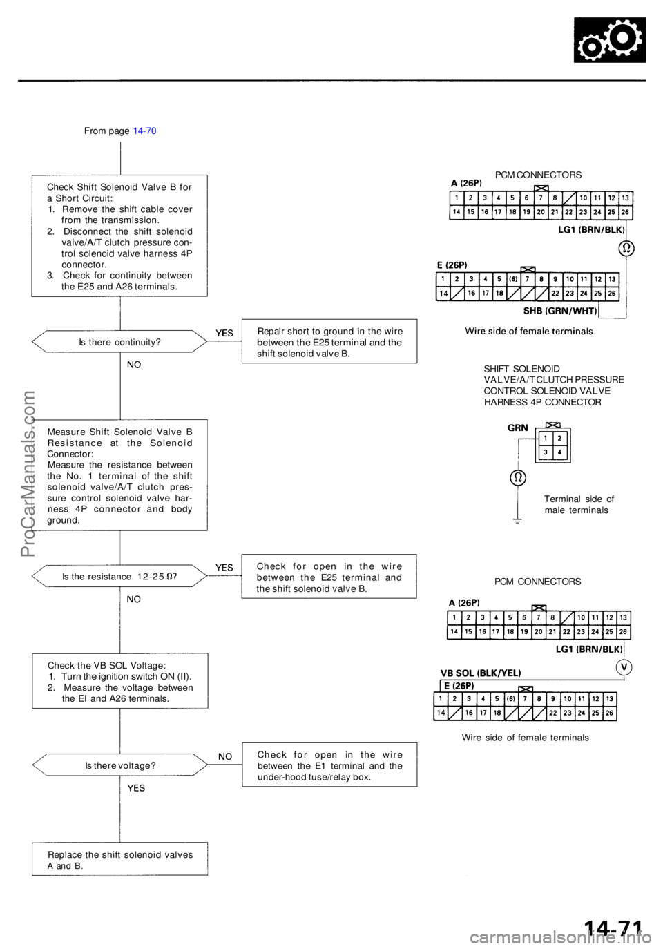
From pag e 14-7 0
Chec k Shif t Solenoi d Valv e B fo r
a Shor t Circuit :
1 . Remov e th e shif t cabl e cove r
fro m th e transmission .
2 . Disconnec t th e shif t solenoi d
valve/A/ T clutc h pressur e con -
tro l solenoi d valv e harnes s 4 P
connector .
3 . Chec k fo r continuit y betwee n
th e E2 5 an d A2 6 terminals .
I s ther e continuity ?
Measur e Shif t Solenoi d Valv e B
Resistanc e a t th e Solenoi d
Connector :
Measur e th e resistanc e betwee n
th e No . 1 termina l o f th e shif t
solenoi d valve/A/ T clutc h pres -
sur e contro l solenoi d valv e har -
nes s 4 P connecto r an d bod y
ground .
Is th e resistanc e 12-2 5
Replac e th e shif t solenoi d valve s
A an d B .
Repai r shor t t o groun d in th e wir ebetwee n th e E2 5 termina l an d th eshif t solenoi d valv e B .
Chec k fo r ope n i n th e wir e
betwee n th e E2 5 termina l an d
th e shif t solenoi d valv e B .
Chec k fo r ope n i n th e wir e
betwee n th e E 1 termina l an d th e
under-hoo d fuse/rela y box . PC
M CONNECTOR S
SHIF T SOLENOI D
VALVE/A/ T CLUTC H PRESSUR E
CONTRO L SOLENOI D VALV E
HARNES S 4 P CONNECTO R
Termina l sid e o f
mal e terminal s
PC M CONNECTOR S
Wir e sid e o f femal e terminal s
Chec
k th e V B SO L Voltage :
1. Tur n th e ignitio n switc h O N (II) .2. Measur e th e voltag e betwee n
th e E l an d A2 6 terminals .
I s ther e voltage ?
ProCarManuals.com
Page 783 of 1954
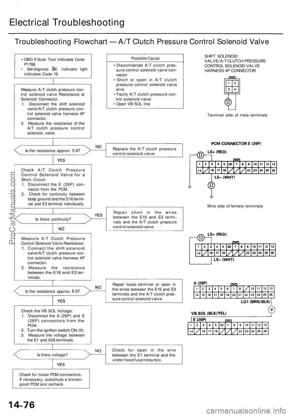
Electrical Troubleshootin g
Troubleshooting Flowchar t — A/ T Clutc h Pressur e Contro l Solenoi d Valv e
• OB D II Sca n Too l indicate s Cod e
P1768 .
• Self-diagnosi s indicator ligh t
indicate s Cod e 16 .
Measur e A/ T clutc h pressur e con -
tro l solenoi d valv e Resistanc e a t
Solenoi d Connector :
1 . Disconnec t th e shif t solenoi d
valve/A/ T clutc h pressur e con -
tro l solenoi d valv e harnes s 4 P
connector .
2 . Measur e th e resistanc e o f th e
A/ T clutc h pressur e contro l
solenoi d valve .
Is th e resistanc e approx . 5
Chec k A/ T Clutc h Pressur e
Control Solenoi d Valv e fo r aShor t Circuit :
1 . Disconnec t th e E (26P ) con -
necto r fro m th e PCM .
2 . Chec k fo r continuit y betwee n
body groun d an d th e E1 6 termi -nal an d E 3 termina l individually .
I s ther e continuity ?
Is th e resistanc e approx .
Chec k th e V B SO L Voltage :
1 . Disconnec t th e A (26P ) an d E
(26P ) connector s fro m th ePCM .2. Tur n th e ignitio n switc h O N (II) .3. Measur e th e voltag e betwee n
th e E 1 an d A2 6 terminals .
I s ther e voltage ?
Chec k fo r loos e PC M connectors .
I f necessary , substitut e a known -
goo d PC M an d recheck . Possibl
e Caus e
• Disconnecte d A/ T clutc h pres -
sur e contro l solenoi d valv e con -
necto r
• Shor t o r ope n i n A/ T clutc h
pressur e contro l solenoi d valv e
wir e
• Fault y A/ T clutc h pressur e con -
tro l solenoi d valv e
• Ope n V B SO L lin e
Replac e th e A/ T clutc h pressur e
contro l solenoi d valve .
Repai r shor t i n th e wire s
betwee n th e E1 6 an d E 3 termi -
nal s an d th e A/ T clutc h pressur e
contro l solenoi d valve .
Repai r loos e termina l o r ope n i n
th e wire s betwee n th e E1 6 an d E 3
terminal s an d th e A/ T clutc h pres -
sur e contro l solenoi d valve .
Chec k fo r ope n i n th e wir e
betwee n th e E 1 termina l an d th eunder-hoo d fuse/rela y box . SHIF
T SOLENOI D
VALVE/A/ T CLUTC H PRESSUR E
CONTRO L SOLENOI D VALV E
HARNES S 4 P CONNECTO R
Termina l sid e o f mal e terminal s
Wir e sid e o f femal e terminal s
Measur e A/ T Clutc h Pressur e
Contro l Solenoi d Valv e Resistance :
1. Connec t th e shif t solenoi dvalve/A/T clutc h pressur e con -
tro l solenoi d valv e harnes s 4 P
connector .
2 . Measur e th e resistanc e
between th e E1 6 an d E 3 ter -minals .
ProCarManuals.com
Page 1081 of 1954
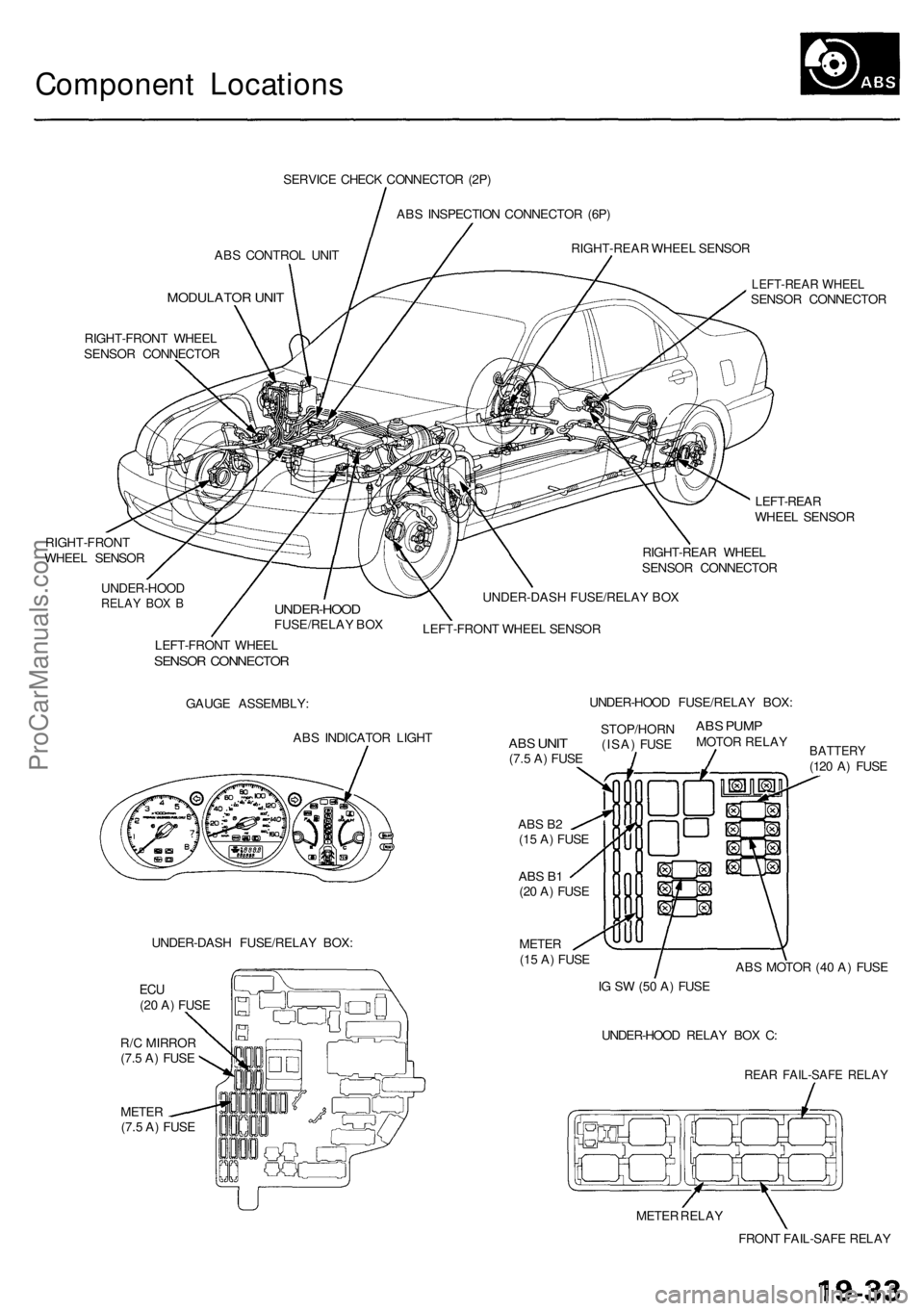
Component Locations
ABS CONTROL UNIT
MODULATOR UNIT
SERVICE CHECK CONNECTOR (2P)
ABS INSPECTION CONNECTOR (6P)
RIGHT-REAR WHEEL SENSOR
RIGHT-FRONT WHEEL
SENSOR CONNECTOR
RIGHT-FRONT
WHEEL SENSOR
LEFT-REAR WHEEL
SENSOR CONNECTOR
LEFT-REAR
WHEEL SENSOR
RIGHT-REAR WHEEL
SENSOR CONNECTOR
UNDER-HOOD
RELAY BOX B
UNDER-HOOD
FUSE/RELAY BOX
UNDER-DASH FUSE/RELAY BOX
LEFT-FRONT WHEEL SENSOR
LEFT-FRONT WHEEL
SENSOR CONNECTOR
GAUGE ASSEMBLY:
ABS INDICATOR LIGHT
UNDER-DASH FUSE/RELAY BOX:
METER
(7.5 A) FUSE
ABS B2
(15 A) FUSE
ABS B1
(20 A) FUSE
METER
(15 A) FUSE
BATTERY
(120 A) FUSE
ABS MOTOR (40 A) FUSE
IG SW (50 A) FUSE
UNDER-HOOD RELAY BOX C:
REAR FAIL-SAFE RELAY
METER RELAY
FRONT FAIL-SAFE RELAY
ABS
UNIT
(7.5 A) FUSE
STOP/HORN
(ISA) FUSE
ABS PUMP
MOTOR RELAY
UNDER-HOOD FUSE/RELAY BOX:
ECU
(20 A) FUSE
R/C MIRROR
(7.5 A) FUSEProCarManuals.com
Page 1087 of 1954
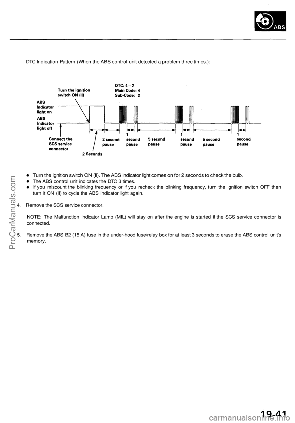
DTC Indication Pattern (When the ABS control unit detected a problem three times.):
Turn the ignition switch ON (II). The ABS indicator light comes on for 2 seconds to check the bulb.
The ABS control unit indicates the DTC 3 times.
If you miscount the blinking frequency or if you recheck the blinking frequency, turn the ignition switch OFF then
turn it ON (II) to cycle the ABS indicator light again.
4. Remove the SCS service connector.
NOTE: The Malfunction Indicator Lamp (MIL) will stay on after the engine is started if the SCS service connector is
connected.
5. Remove the ABS B2 (15 A) fuse in the under-hood fuse/relay box for at least 3 seconds to erase the ABS control unit's
memory.ProCarManuals.com
Page 1089 of 1954
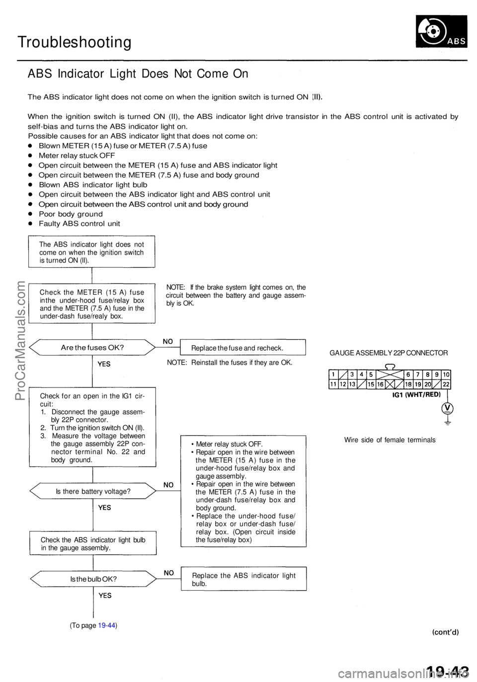
Troubleshooting
ABS Indicato r Ligh t Doe s No t Com e O n
Th e AB S indicato r ligh t doe s no t com e o n whe n th e ignitio n switc h is turne d O N
Whe n th e ignitio n switc h i s turne d O N (II) , th e AB S indicator light driv e transisto r i n th e AB S contro l uni t i s activate d b y
self-bia s an d turn s th e AB S indicato r ligh t on .
Possibl e cause s fo r a n AB S indicato r ligh t tha t doe s no t com e on :
Blow n METE R (1 5 A ) fus e o r METE R (7. 5 A ) fus e
Mete r rela y stuc k OF F
Ope n circui t betwee n th e METE R (1 5 A ) fus e an d AB S indicato r ligh t
Ope n circui t betwee n th e METE R (7. 5 A ) fus e an d bod y groun d
Blow n AB S indicato r ligh t bul b
Ope n circui t betwee n th e AB S indicato r ligh t an d AB S contro l uni t
Ope n circui t betwee n th e AB S contro l uni t an d bod y groun d
Poor bod y groun d
Fault y AB S contro l uni t
The AB S indicato r ligh t doe s no t
com e o n whe n th e ignitio n switc h
i s turne d O N (II) .
Chec k th e METE R (1 5 A ) fus e
i n th e under-hoo d fuse/rela y bo x
an d th e METE R (7. 5 A ) fus e in th e
under-das h fuse/real y box . NOTE
: I f th e brak e syste m ligh t come s on , th e
circui t betwee n th e batter y an d gaug e assem -
bly is OK .
Are th e fuse s OK ?Replac e th e fus e an d recheck .
NOTE : Reinstal l th e fuse s i f the y ar e OK . GAUG
E ASSEMBL Y 22 P CONNECTO R
Chec k fo r a n ope n in th e IG 1 cir -
cuit :
1 . Disconnec t th e gaug e assem -
bl y 22 P connector .
2. Tur n th e ignitio n switc h O N (II) .3. Measur e th e voltag e betwee n
th e gaug e assembl y 22 P con -
necto r termina l No . 2 2 an d
bod y ground .
I s ther e batter y voltage ? Mete
r rela y stuc k OFF .
Repai r ope n in th e wir e betwee n
th e METE R (1 5 A ) fus e i n th e
under-hoo d fuse/rela y bo x an d
gaug e assembly .
Repai r ope n in th e wir e betwee n
th e METE R (7. 5 A ) fus e i n th e
under-das h fuse/rela y bo x an d
bod y ground .
Replac e th e under-hoo d fuse /
rela y bo x o r under-das h fuse /
rela y box . (Ope n circui t insid e
th e fuse/rela y box ) Wir
e sid e o f femal e terminal s
Is th e bul b OK ?Replac e th e AB S indicato r ligh t
bulb .
(T o pag e 19-44 )
Chec
k th e AB S indicato r ligh t bul b
i n th e gaug e assembly .
ProCarManuals.com
Page 1091 of 1954
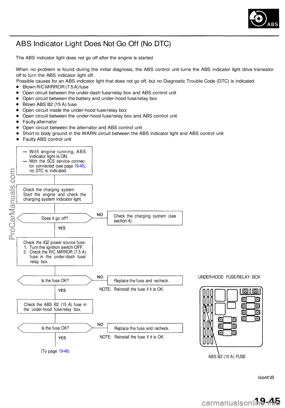
ABS Indicato r Ligh t Doe s No t G o Of f (N o DTC )
The AB S indicato r ligh t doe s no t g o of f afte r th e engine is starte d
Whe n n o proble m is foun d durin g th e initia l diagnosis , th e AB S contro l uni t turn s th e AB S indicato r ligh t driv e transisto r
of f t o tur n th e AB S indicato r ligh t off .
Possibl e cause s fo r a n AB S indicato r ligh t tha t doe s no t g o off , bu t n o Diagnosti c Troubl e Cod e (DTC ) i s indicated :
Blow n R/ C MIRRO R (7. 5 A ) fus e
Ope n circui t betwee n th e under-das h fuse/rela y bo x an d AB S contro l uni t
Ope n circui t betwee n th e batter y an d under-hoo d fuse/rela y bo x
Blow n AB S B 2 (1 5 A ) fus e
Ope n circui t insid e th e under-hoo d fuse/rela y bo x
Ope n circui t betwee n th e under-hoo d fuse/rela y bo x an d AB S contro l uni t
Fault y alternato r
Ope n circui t betwee n th e alternato r an d AB S contro l uni t
Shor t t o bod y groun d in th e WAR N circui t betwee n th e AB S indicator light an d AB S contro l uni t
Fault y AB S contro l uni t
Wit h engin e running , AB Sindicato r ligh t i s ON .With th e SC S servic e connec -
to r connecte d (se e pag e 19-40 ),
n o DT C is indicated .
Chec k th e chargin g system :
Star t th e engin e an d chec k th e
chargin g syste m indicato r light .
Does i t g o off ?
Chec k th e IG 2 powe r sourc e fuse :
1. Tur n th e ignitio n switc h OFF .2. Chec k th e R/ C MIRRO R (7. 5 A )
fus e i n th e under-das h fuse /
rela y box .
I s th e fus e OK ?
Chec k th e AB S B 2 (1 5 A ) fus e i n
th e under-hoo d fuse/rela y box .
I s th e fus e OK ?
(T o pag e 19-46 ) Chec
k th e chargin g syste m (se e
sectio n 4) .
Replac e th e fus e an d recheck . UNDER-HOO
D FUSE/RELA Y BO X
NOTE : Reinstal l th e fus e i f i t i s OK .
Replac e th e fus e an d recheck .
NOTE : Reinstal l th e fus e i f i t i s OK .
ABS B 2 (1 5 A ) FUS E
ProCarManuals.com