wheel ACURA RL KA9 1996 Service Owner's Manual
[x] Cancel search | Manufacturer: ACURA, Model Year: 1996, Model line: RL KA9, Model: ACURA RL KA9 1996Pages: 1954, PDF Size: 61.44 MB
Page 810 of 1954
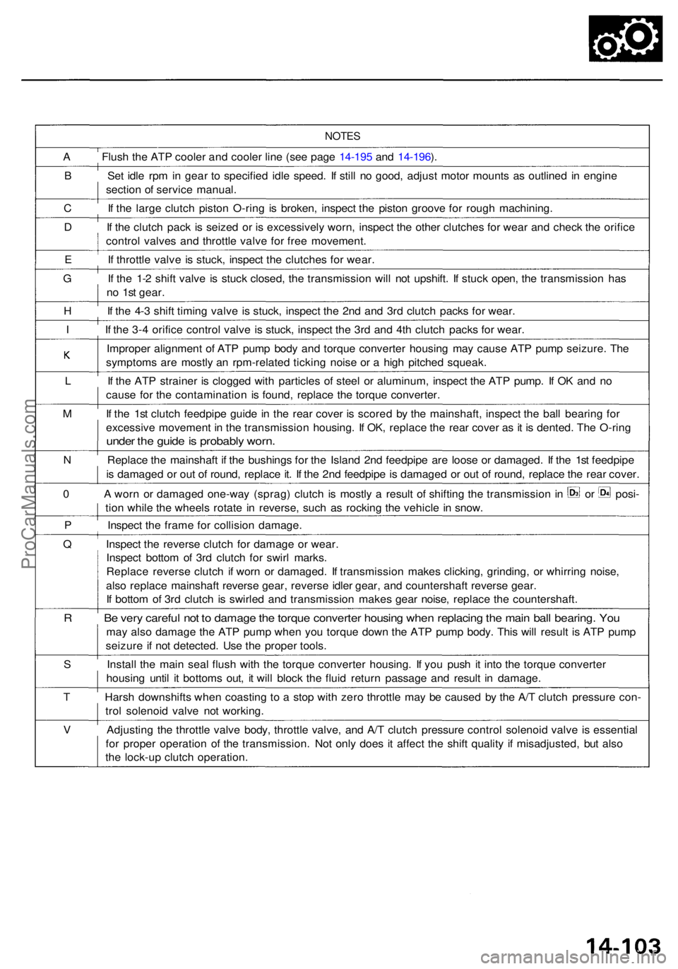
NOTES
A Flus h th e AT P coole r an d coole r lin e (se e pag e 14-19 5 an d 14-196 ).
B Se t idl e rp m in gea r t o specifie d idl e speed . I f stil l n o good , adjus t moto r mount s a s outline d i n engin e
sectio n o f servic e manual .
C I f th e larg e clutc h pisto n O-rin g i s broken , inspec t th e pisto n groov e fo r roug h machining .
D I f th e clutc h pac k i s seize d o r i s excessivel y worn , inspec t th e othe r clutche s fo r wea r an d chec k th e orific e
contro l valve s an d throttl e valv e fo r fre e movement .
E I f throttl e valv e i s stuck , inspec t th e clutche s fo r wear .
G I f th e 1- 2 shif t valv e i s stuc k closed , th e transmissio n wil l no t upshift . I f stuc k open , th e transmissio n ha s
n o 1s t gear .
H I f th e 4- 3 shif t timin g valv e i s stuck , inspec t th e 2n d an d 3r d clutc h pack s fo r wear .
I I f th e 3- 4 orific e contro l valv e i s stuck , inspec t th e 3r d an d 4t h clutc h pack s fo r wear .
Imprope r alignmen t o f AT P pum p bod y an d torqu e converte r housin g ma y caus e AT P pum p seizure . Th e
symptom s ar e mostl y a n rpm-relate d tickin g nois e o r a hig h pitche d squeak .
L I f th e ATP straine r i s clogge d wit h particle s o f stee l o r aluminum , inspec t th e AT P pump . I f O K an d n o
caus e fo r th e contaminatio n i s found , replac e th e torqu e converter .
M I f th e 1s t clutc h feedpip e guid e i n th e rea r cove r i s score d b y th e mainshaft , inspec t th e bal l bearin g fo r
excessiv e movemen t i n th e transmissio n housing . I f OK , replac e th e rea r cove r a s i t i s dented . Th e O-rin g
under th e guid e is probabl y worn .
N Replac e th e mainshaf t i f th e bushing s fo r th e Islan d 2n d feedpip e ar e loos e o r damaged . I f th e 1s t feedpip e
i s damage d o r ou t o f round , replac e it . I f th e 2n d feedpip e is damage d o r ou t o f round , replac e th e rea r cover .
0 A worn o r damage d one-wa y (sprag ) clutc h i s mostl y a resul t o f shiftin g th e transmissio n in o r posi -
tio n whil e th e wheel s rotat e i n reverse , suc h a s rockin g th e vehicl e in snow .
P Inspec t th e fram e fo r collisio n damage .
Q Inspec t th e revers e clutc h fo r damag e o r wear .
Inspec t botto m o f 3r d clutc h fo r swir l marks .
Replac e revers e clutc h i f wor n o r damaged . I f transmissio n make s clicking , grinding , o r whirrin g noise ,
als o replac e mainshaf t revers e gear , revers e idle r gear , an d countershaf t revers e gear .
I f botto m o f 3r d clutc h i s swirle d an d transmissio n make s gea r noise , replac e th e countershaft .
R B e ver y carefu l no t t o damag e th e torqu e converte r housin g whe n replacin g th e mai n bal l bearing . Yo u
may als o damag e th e AT P pum p whe n yo u torqu e dow n th e ATP pum p body . Thi s wil l resul t i s AT P pum p
seizur e i f no t detected . Us e th e prope r tools .
S Instal l th e mai n sea l flus h wit h th e torqu e converte r housing . I f yo u pus h i t int o th e torqu e converte r
housin g unti l i t bottom s out , i t wil l bloc k th e flui d retur n passag e an d resul t i n damage .
T Hars h downshift s whe n coastin g t o a sto p wit h zer o throttl e ma y b e cause d b y th e A/ T clutc h pressur e con -
tro l solenoi d valv e no t working .
V Adjustin g th e throttl e valv e body , throttl e valve , an d A/ T clutc h pressur e contro l solenoi d valv e i s essentia l
fo r prope r operatio n o f th e transmission . No t onl y doe s i t affec t th e shif t qualit y i f misadjusted , bu t als o
th e lock-u p clutc h operation .
ProCarManuals.com
Page 811 of 1954
Road Tes t
NOTE : War m u p th e engin e to norma l operatin g temperatur e (th e radiato r fa n come s on) .
1. Appl y parkin g brak e an d bloc k th e wheels . Star t th e engine , the n shif t t o positio n whil e pressin g th e brak e pedal .
Pres s th e accelerato r peda l an d releas e it suddenly . Th e engin e shoul d no t stall .
2. Repea t th e sam e tes t i n position .
3. Test-driv e th e vehicl e o n th e fla t roa d in position . Chec k tha t th e shif t point s occu r a t th e approximat e speed s
shown o n th e nex t page . Als o chec k fo r abnorma l nois e an d clutc h slippage .
NOTE : Throttl e positio n senso r voltag e represent s th e throttl e opening .
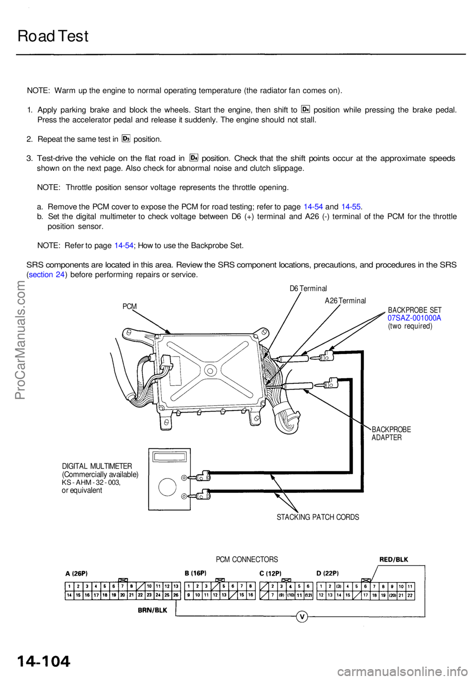
a . Remov e th e PC M cove r t o expos e th e PC M fo r roa d testing ; refe r t o pag e 14-5 4 an d 14-55 .
b . Se t th e digita l multimete r t o chec k voltag e betwee n D 6 (+ ) termina l an d A2 6 (- ) termina l o f th e PC M fo r th e throttl e
positio n sensor .
NOTE : Refe r t o pag e 14-54 ; Ho w to us e th e Backprob e Set .
SRS component s ar e locate d in thi s area . Revie w th e SR S componen t locations , precautions , an d procedure s in th e SR S
(sectio n 24 ) befor e performin g repair s o r service .
PCM
D6 Termina l
DIGITAL MULTIMETE R(Commercially available )KS - AH M - 3 2 - 003 ,or equivalen t
BACKPROB E SE T07SAZ-001000A(two required )
BACKPROB EADAPTER
STACKIN G PATC H CORD S
A26 Termina l
PCM CONNECTOR S
ProCarManuals.com
Page 814 of 1954
Stall Speed
Test
CAUTION:
• To prevent transmission damage, do not test stall speed for more than 10 seconds at a time.
• Do not shift the lever while raising the engine speed.
• Be sure to remove the pressure gauge before testing stall speed.
1. Engage the parking brake, and block the front wheels.
2. Connect a tachometer to the engine, and start the engine.
3. Make sure the A/C switch is OFF.
4. After the engine has warmed up to normal operating temperature (the radiator fan comes on), shift into position.
5. Fully press the brake pedal and accelerator for 6 to 8 seconds, and note engine speed.
6. Allow two minutes for cooling, then repeat the test in and positions.
NOTE:
• Stall speed tests should be used for diagnostic purposes only.
• Stall speed should be the same in and positions.
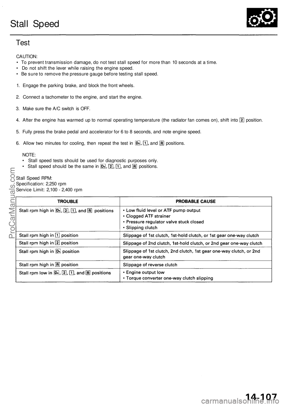
Stall Speed RPM:
Specification: 2,250 rpm
Service Limit: 2,100 - 2,400 rpmProCarManuals.com
Page 816 of 1954

Pressure Testin g
• Whil e testing , b e carefu l o f th e rotatin g fron t wheels .
• Mak e sur e lifts , jack s an d safet y stand s ar e place d properl y (se e sectio n 1 ).
CAUTION :
• Befor e testing , b e sur e th e transmissio n flui d is fille d to th e prope r level .
• War m up th e engin e befor e testing .
1 . Rais e th e fron t o f th e vehicle , an d suppor t i t wit h safet y stands .
2 . Se t th e parkin g brake , an d bloc k rea r wheel s securely .
3. Allo w th e fron t wheel s to rotat e freely .
4. War m u p th e engin e (th e radiator fan come s on) , the n sto p an d connec t a tachometer .
5 . Connec t th e specia l too l t o lin e pressur e inspectio n hole .
TORQUE : 1 8 N- m (1. 8 kgf-m , 1 3 Ibf-ft )
CAUTION : Connec t th e oi l pressur e gaug e securely , b e sur e no t t o allo w dus t an d othe r foreig n particle s t o ente r th e
inspectio n hole .
LINE PRESSUR E
INSPECTIO N HOL E
A/ T OI L PRESSUR E GAUG E
SE T W/PANE L
07406-002040 0
A/T LO W PRESSUR E
GAUG E W/PANE L
07406-007030 0
A/T PRESSUR E HOS E
ADAPTE R
07MAJ-PY4012 0(4 Required )
A/ T PRESSUR E HOSE ,
2210 mm07MAJ-PY4011 A(4 Required )
ProCarManuals.com
Page 819 of 1954
Lower Valv e Bod y Assembl y
Removal/Installatio n
Make sur e lifts , jack s an d safet y stand s ar e
place d properl y (se e sectio n 1 ).
1 . Rais e th e fron t o f th e vehicle , an d suppor t i t wit h
safet y stand s (se e sectio n 1 ).
2 . Se t th e parkin g brake , an d bloc k bot h rea r wheel s
securely .
3. Shif t th e transmissio n to th e position .
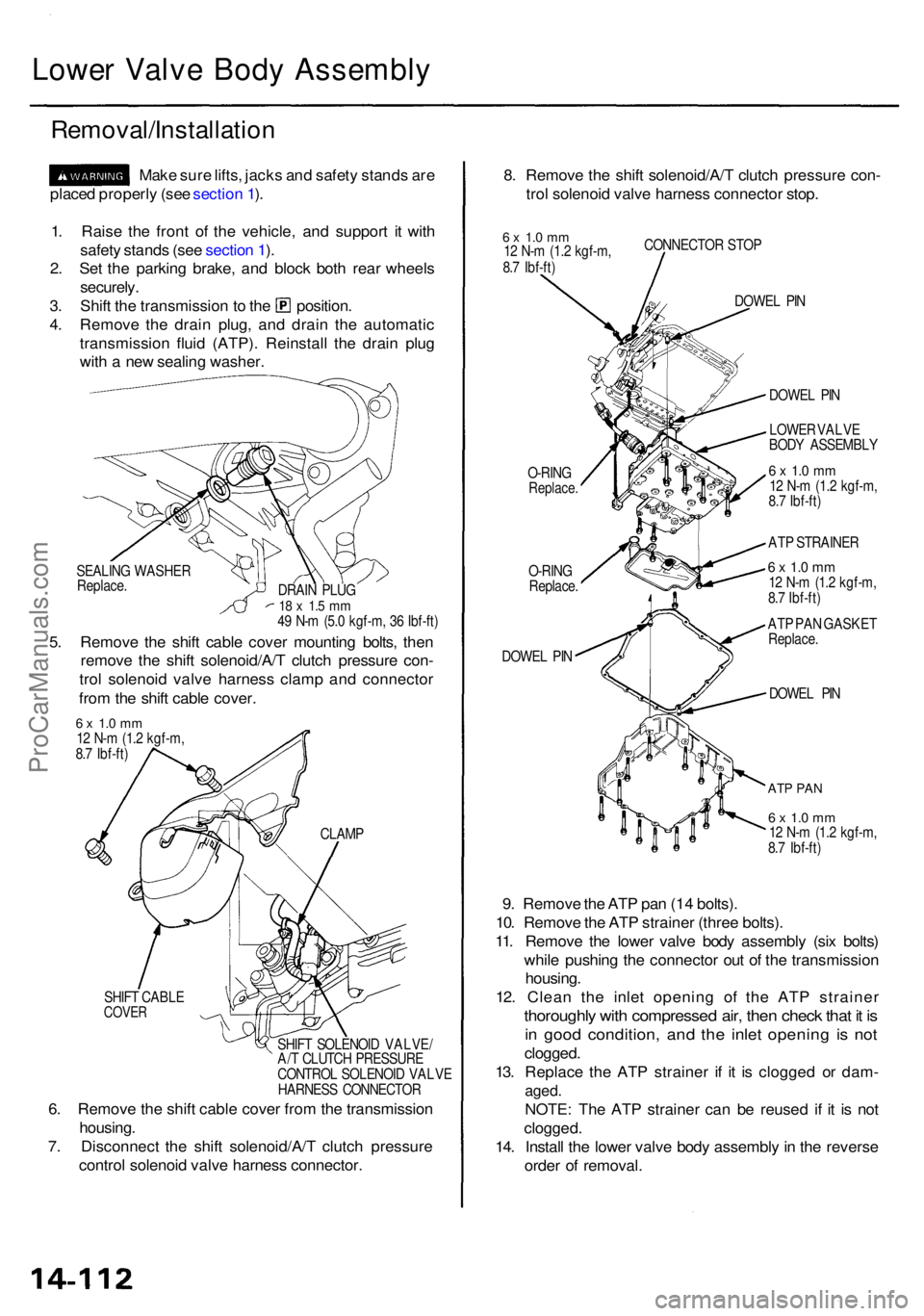
4 . Remov e th e drai n plug , an d drai n th e automati c
transmissio n flui d (ATP) . Reinstal l th e drai n plu g
wit h a ne w sealin g washer . 8
. Remov e th e shif t solenoid/A/ T clutc h pressur e con -
tro l solenoi d valv e harnes s connecto r stop .
6 x 1. 0 m m12 N- m (1. 2 kgf-m ,
8. 7 Ibf-ft ) CONNECTO
R STO P
O-RIN G
Replace .
O-RING
Replace .
DOWE L PI N DOWE
L PI N
DOWE L PI N
ATP PA N
6 x 1. 0 m m12 N- m (1. 2 kgf-m ,
8. 7 Ibf-ft )
9. Remov e th e AT P pa n (1 4 bolts) .
10 . Remov e th e AT P straine r (thre e bolts) .
11 . Remov e th e lowe r valv e bod y assembl y (si x bolts )
whil e pushin g th e connecto r ou t o f th e transmissio n
housing .
12 . Clea n th e inle t openin g o f th e AT P straine r
thoroughly wit h compresse d air , the n chec k tha t i t i s
in goo d condition , an d th e inle t openin g i s no t
clogged .
13 . Replac e th e AT P straine r i f i t i s clogge d o r dam -
aged.
NOTE : Th e AT P straine r ca n b e reuse d i f i t i s no t
clogged .
14. Instal l th e lowe r valv e bod y assembl y in th e revers e
orde r o f removal .
SEALING WASHE R
Replace .
5. Remov e th e shif t cabl e cove r mountin g bolts , the n
remov e th e shif t solenoid/A/ T clutc h pressur e con -
tro l solenoi d valv e harnes s clam p an d connecto r
fro m th e shif t cabl e cover .
DRAIN PLU G18 x 1. 5 m m49 N- m (5. 0 kgf-m , 3 6 Ibf-ft ) DOWE
L PI N
LOWE R VALV E
BOD Y ASSEMBL Y
6 x 1. 0 m m12 N- m (1. 2 kgf-m ,
8. 7 Ibf-ft )
AT P STRAINE R
6 x 1. 0 m m12 N- m (1. 2 kgf-m ,
8. 7 Ibf-ft )
AT P PA N GASKE T
Replace .
6 x 1. 0 m m12 N- m (1. 2 kgf-m ,
8. 7 Ibf-ft )
SHIF T CABL E
COVER
SHIFT SOLENOI D VALVE /
A/ T CLUTC H PRESSUR E
CONTRO L SOLENOI D VALV E
HARNES S CONNECTO R
CLAM
P
6. Remov e th e shif t cabl e cove r fro m th e transmissio n
housing .
7 . Disconnec t th e shif t solenoid/A/ T clutc h pressur e
contro l solenoi d valv e harnes s connector .
ProCarManuals.com
Page 909 of 1954
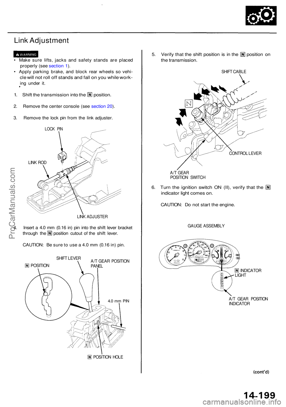
Link Adjustmen t
• Mak e sur e lifts , jack s an d safet y stand s ar e place d
properl y (se e sectio n 1 ).
• Appl y parkin g
brake, and bloc k rea r wheel s s o vehi -
cle wil l no t rol l of f stand s an d fal l o n yo u whil e work -
ing unde r it .
1. Shif t the transmissio n into the position .
2. Remov e th e cente r consol e (se e sectio n 20 ).
3 . Remov e th e loc k pi n fro m th e lin k adjuster .
LINK RO D
LINK ADJUSTE R
4. Inser t a 4. 0 m m (0.1 6 in ) pi n int o th e shif t leve r bracke t
through th e positio n cutou t o f th e shif t lever .
CAUTION : B e sur e t o us e a 4. 0 m m (0.1 6 in ) pin .
SHIF T LEVE R
POSITIO NA/T GEA R POSITIO N
PANE L
POSITIO N HOL E
5. Verif y tha t th e shif t positio n is i n th e positio n o n
the transmission .
SHIFT CABL E
CONTRO L LEVE R
A/ T GEA R
POSITIO N SWITC H
6. Tur n th e ignitio n switc h O N (II) , verif y tha t th e
indicato r ligh t come s on .
CAUTION : D o no t star t th e engine .
GAUGE ASSEMBL Y
INDICATOR
LIGH T
A/ T GEA R POSITIO N
INDICATO R
LOCK PI N
4.0 m m PI N
ProCarManuals.com
Page 911 of 1954
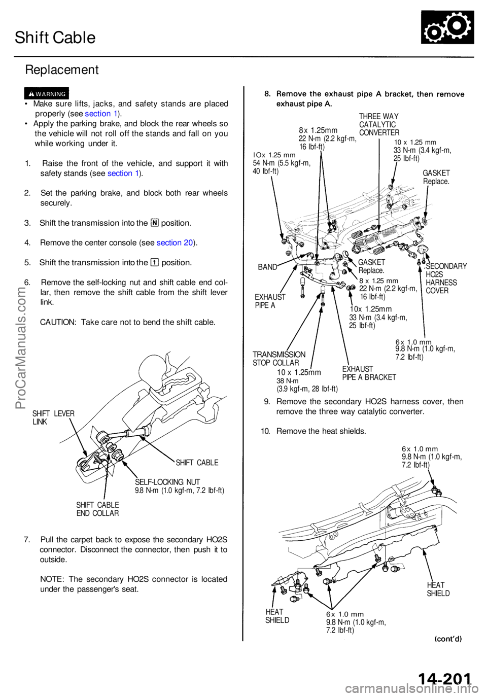
Shift Cabl e
Replacemen t
• Mak e sur e lifts , jacks , an d safet y stand s ar e place d
properl y (se e sectio n
1).
• Appl y th e parkin g brake , an d bloc k th e rea r wheel s s o
th e vehicl e wil l no t rol l of f th e stand s an d fal l o n yo u
whil e workin g unde r it .
1 . Rais e th e fron t o f th e vehicle , an d suppor t i t wit h
safet y stand s (se e sectio n
1).
2 . Se t th e parkin g brake , an d bloc k bot h rea r wheel s
securely .
3. Shif t th e transmissio n int o th e position .
4. Remov e th e cente r consol e (se e sectio n 20 ).
5 . Shif t th e transmissio n int o th e position .
6. Remov e th e self-lockin g nu t an d shif t cabl e en d col -
lar , the n remov e th e shif t cabl e fro m th e shif t leve r
link .
CAUTION : Tak e car e no t t o ben d th e shif t cable .
SHIFT LEVE RLINK
SHIF T CABL E
SELF-LOCKIN G NU T9.8 N- m (1. 0 kgf-m , 7.2 Ibf-ft )
SHIFT CABL E
EN D COLLA R
7. Pul l th e carpe t bac k t o expos e th e secondar y HO2 S
connector . Disconnec t th e connector , the n pus h i t t o
outside .
NOTE : Th e secondar y HO2 S connecto r i s locate d
unde r th e passenger' s seat .
BAND
EXHAUS TPIPE A
TRANSMISSIO NSTOP COLLA R
10 x 1.25m m38 N- m(3.9 kgf-m , 28 Ibf-ft )
SECONDAR Y
HO2 S
HARNES S
COVE R
6x 1. 0 m m9.8 N- m (1. 0 kgf-m ,7.2 Ibf-ft )
EXHAUS T
PIP E A BRACKE T
9. Remov e th e secondar y HO2 S harnes s cover , the n
remov e th e thre e wa y catalyti c converter .
10 . Remov e th e hea t shields .
6x 1. 0 m m9.8 N- m (1. 0 kgf-m ,7.2 Ibf-ft )
HEATSHIEL D6x 1.0 m m9.8 N- m (1. 0 kgf-m ,7.2 Ibf-ft )
HEAT
SHIEL D
8x 1.25m m22 N- m (2. 2 kgf-m ,16 Ibf-ft )
THRE E WA Y
CATALYTI C
CONVERTE R
10 x 1.2 5 mm33 N- m (3. 4 kgf-m ,25 Ibf-ft )
GASKE TReplace .
lOx 1.2 5 mm54 N- m (5. 5 kgf-m ,40 Ibf-ft )
GASKE T
Replace .
8 x 1.2 5 mm22 N- m (2. 2 kgf-m ,16 Ibf-ft )
10x 1.25m m33 N- m (3. 4 kgf-m ,25 Ibf-ft )
ProCarManuals.com
Page 916 of 1954
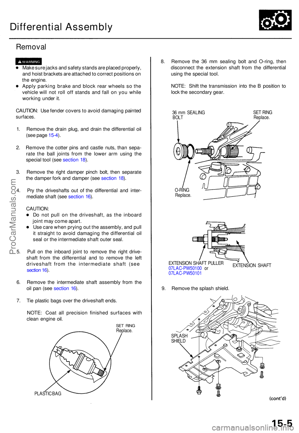
Differential Assembly
Removal
Make sur e jack s an d safet y stand s ar e place d properly ,
an d hois t bracket s ar e attache d to correc t position s o n
th e engine .
Appl y parkin g brak e an d bloc k rea r wheel s s o th e
vehicl e wil l no t rol l of f stand s an d fal l o n yo u whil e
workin g unde r it .
CAUTION : Us e fende r cover s to avoi d damagin g painte d
surfaces .
1. Remov e th e drai n plug , an d drai n th e differentia l oi l
(se e pag e 15-4 ).
2 . Remov e th e cotte r pin s an d castl e nuts , tha n sepa -
rat e th e bal l joint s fro m th e lowe r ar m usin g th e
specia l too l (se e sectio n 18 ).
3 . Remov e th e righ t dampe r pinc h bolt , the n separat e
th e dampe r for k an d dampe r (se e sectio n 18 ).
4 . Pr y th e driveshaft s ou t o f th e differentia l an d inter -
mediat e shaf t (se e sectio n 16 ).
CAUTION :
D o no t pul l o n th e driveshaft , a s th e inboar d
join t ma y com e apart .
Us e car e whe n pryin g ou t th e assembly , an d pul l
i t straigh t t o avoi d damagin g th e differentia l oi l
sea l o r th e intermediat e shaf t oute r seal .
5 . Pul l o n th e inboar d join t t o remov e th e righ t drive -
shaf t fro m th e differentia l an d t o remov e th e lef t
driveshaft from the intermediate shaft (see
section 16 ).
6 . Remov e th e intermediat e shaf t assembl y fro m th e
oi l pa n (se e sectio n 16 ).
7 . Ti e plasti c bag s ove r th e driveshaf t ends .
NOTE : Coa t al l precisio n finishe d surface s wit h
clea n engin e oil .
SE T RIN GReplace .
PLASTIC BA G
8. Remov e th e 3 6 m m sealin g bol t an d O-ring , the n
disconnec t th e extensio n shaf t fro m th e differentia l
usin g th e specia l tool .
NOTE : Shif t th e transmissio n int o th e B positio n t o
loc k th e secondar y gear .
36 m m SEALIN GBOLTSET RIN GReplace .
O-RINGReplace .
EXTENSIO N SHAF T PULLE R
07LAC-PW5010 0 o r
07LAC-PW5010 1 EXTENSIO
N SHAF T
9. Remov e th e splas h shield .
SPLAS HSHIELD
ProCarManuals.com
Page 945 of 1954
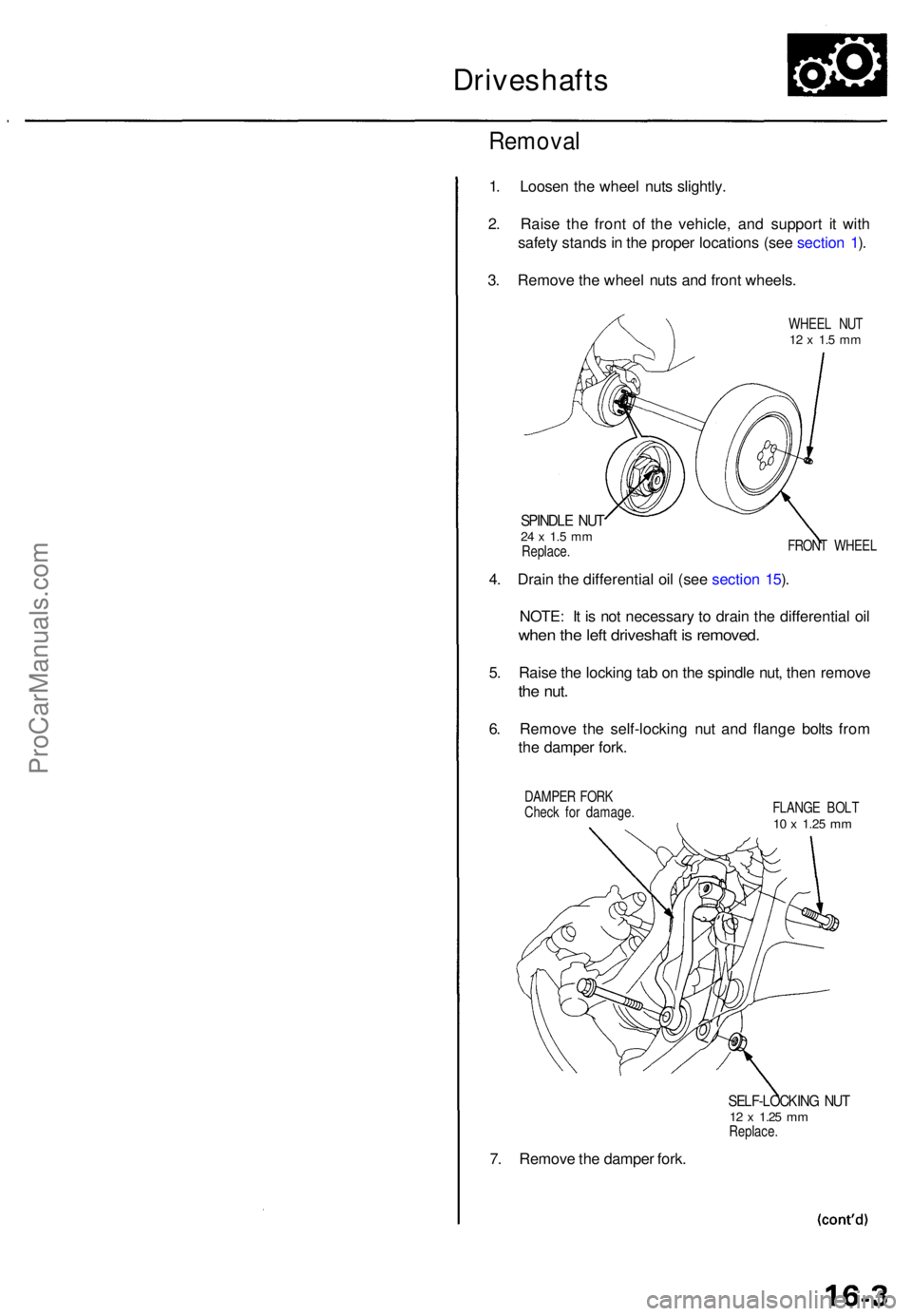
Driveshafts
Removal
1. Loose n th e whee l nut s slightly .
2 . Rais e th e fron t o f th e vehicle , an d suppor t i t wit h
safet y stand s in th e prope r location s (se e sectio n 1 ).
3 . Remov e th e whee l nut s an d fron t wheels .
WHEEL NU T12 x 1. 5 m m
SPINDL E NU T24 x 1. 5 m mReplace . FRON
T WHEE L
4. Drai n th e differentia l oi l (se e sectio n 15 ).
NOTE : I t i s no t necessar y t o drai n th e differentia l oi l
whe n th e lef t driveshaf t i s removed .
5. Rais e th e lockin g ta b o n th e spindl e nut , the n remov e
the nut .
6. Remov e th e self-lockin g nu t an d flang e bolt s fro m
th e dampe r fork .
DAMPE R FOR K
Chec k fo r damage . FLANG
E BOL T
10 x 1.2 5 mm
7. Remov e th e dampe r fork .
SELF-LOCKIN G NU T12 x 1.2 5 mmReplace .
ProCarManuals.com
Page 959 of 1954
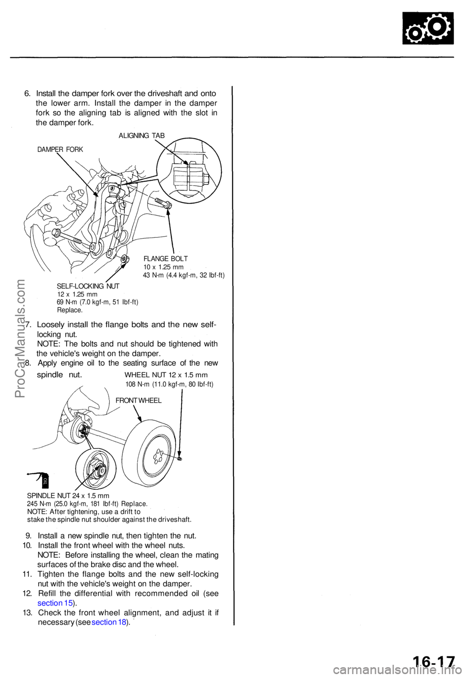
6. Instal l th e dampe r for k ove r th e driveshaf t an d ont o
the lowe r arm . Instal l th e dampe r i n th e dampe r
for k s o th e alignin g ta b i s aligne d wit h th e slo t i n
th e dampe r fork .
ALIGNIN G TAB
DAMPE R FOR K
FLANG E BOL T10 x 1.2 5 mm43 N- m (4. 4 kgf-m , 3 2 Ibf-ft )
SELF-LOCKIN G NU T12 x 1.2 5 mm69 N- m (7. 0 kgf-m , 5 1 Ibf-ft )Replace .
7. Loosel y instal l th e flang e bolt s an d th e ne w self -
lockin g nut .
NOTE : Th e bolt s an d nu t shoul d b e tightene d wit h
th e vehicle' s weigh t o n th e damper .
8 . Appl y engin e oi l t o th e seatin g surfac e o f th e ne w
spindl e nut . WHEE L NU T 1 2 x 1. 5 m m
108 N- m (11. 0 kgf-m , 8 0 Ibf-ft )
SPINDL E NU T 2 4 x 1. 5 m m245 N- m (25. 0 kgf-m , 18 1 Ibf-ft ) Replace .NOTE: Afte r tightening , us e a drif t t o
stak e th e spindl e nu t shoulde r agains t th e driveshaft .
9. Instal l a ne w spindl e nut , the n tighte n th e nut .
10 . Instal l th e fron t whee l wit h th e whee l nuts .
NOTE : Befor e installin g th e wheel , clea n th e matin g
surface s o f th e brak e dis c an d th e wheel .
11 . Tighten the flang e bolt s an d th e ne w self-lockin g
nu t wit h th e vehicle' s weigh t o n th e damper .
12 . Refil l th e differentia l with recommende d oi l (se e
sectio n 15 ).
13 . Chec k th e fron t whee l alignment , an d adjus t i t i f
necessar y (se e sectio n 18 ).
FRON T WHEE L
ProCarManuals.com