wheel ACURA RL KA9 1996 Service Repair Manual
[x] Cancel search | Manufacturer: ACURA, Model Year: 1996, Model line: RL KA9, Model: ACURA RL KA9 1996Pages: 1954, PDF Size: 61.44 MB
Page 1949 of 1954
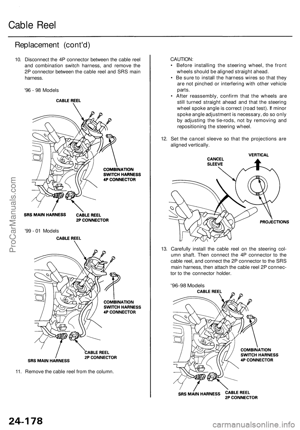
11. Remove the cable reel from the column.
13. Carefully install the cable reel on the steering col-
umn shaft. Then connect the 4P connector to the
cable reel, and connect the 2P connector to the SRS
main harness, then attach the cable reel 2P connec-
tor to the connector holder.
'96-98 Models
'99 - 01 Models
CAUTION:
• Before installing the steering wheel, the front
wheels should be aligned straight ahead.
• Be sure to install the harness wires so that they
are not pinched or interfering with other vehicle
parts.
• After reassembly, confirm that the wheels are
still turned straight ahead and that the steering
wheel spoke angle is correct (road test). If minor
spoke angle adjustment is necessary, do so only
by adjusting the tie-rods, not by removing and
repositioning the steering wheel.
12. Set the cancel sleeve so that the projections are
aligned vertically.
Replacement (cont'd)
10. Disconnect the 4P connector between the cable reel
and combination switch harness, and remove the
2P connector between the cable reel and SRS main
harness.
'96 - 98 Models
Cable ReelProCarManuals.com
Page 1950 of 1954
'99 - 01 Models
'99 - 01 Models
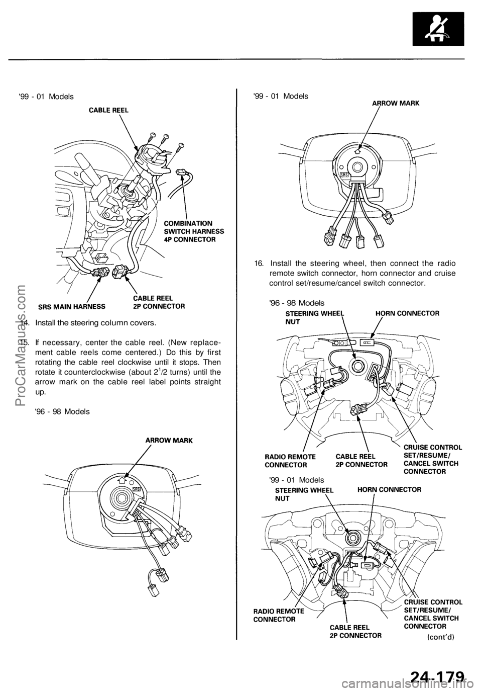
16. Install the steering wheel, then connect the radio
remote switch connector, horn connector and cruise
control set/resume/cancel switch connector.
'96 - 98 Models
14. Install the steering column covers.
15. If necessary, center the cable reel. (New replace-
ment cable reels come centered.) Do this by first
rotating the cable reel clockwise until it stops. Then
rotate it counterclockwise (about 21/2 turns) until the
arrow mark on the cable reel label points straight
up.
'96 - 98 Models
'99 - 01 ModelsProCarManuals.com
Page 1951 of 1954
Replacement (cont'd )
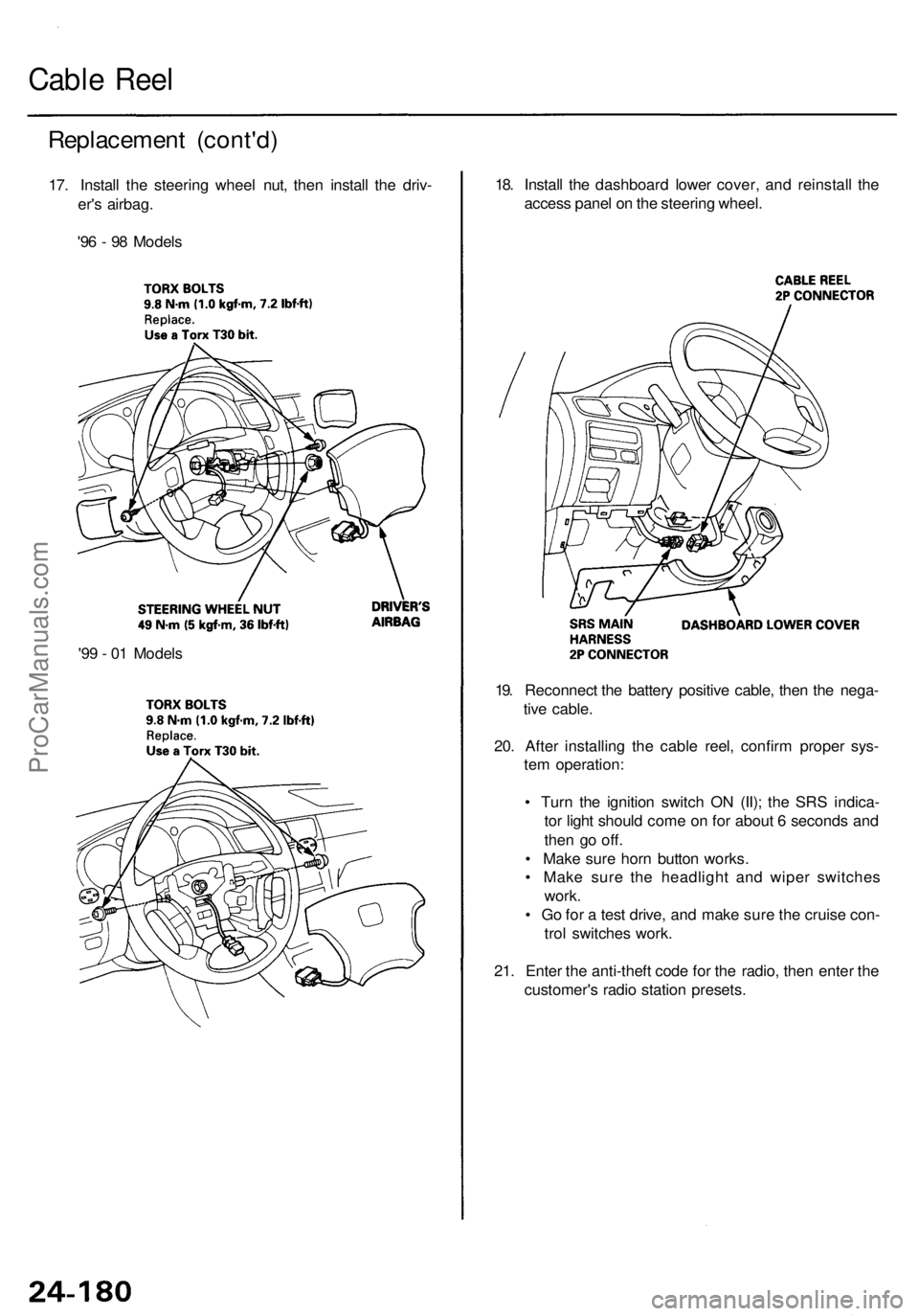
17. Instal l th e steerin g whee l nut , the n instal l th e driv -
er' s airbag .
'9 6 - 9 8 Model s
Cable Ree l
18. Instal l th e dashboar d lowe r cover , an d reinstal l th e
acces s pane l o n th e steerin g wheel .
19 . Reconnec t th e batter y positiv e cable , the n th e nega -
tiv e cable .
20 . Afte r installin g th e cabl e reel , confir m prope r sys -
te m operation :
• Tur n th e ignitio n switc h O N (II) ; th e SR S indica -
to r ligh t shoul d com e o n fo r abou t 6 second s an d
the n g o off .
• Mak e sur e hor n butto n works .
• Mak e sur e th e headligh t an d wipe r switche s
work .
• G o fo r a tes t drive , an d mak e sur e th e cruis e con -
tro l switche s work .
21 . Ente r th e anti-thef t cod e fo r th e radio , the n ente r th e
customer' s radi o statio n presets .
'9
9 - 0 1 Model s
ProCarManuals.com
Page 1952 of 1954
SRS Uni t
Replacemen t
CAUTION:
• Befor e disconnectin g an y par t o f th e SR S wir e har -
ness , disconnec t th e airba g connectors , sea t bel t ten -
sione r connector s an d sid e airba g connectors .
• Durin g installatio n o r replacement , d o no t bum p
(impac t wrench , hamme r etc. ) th e are a nea r th e SR S
unit.
• D o no t damag e th e SR S uni t terminal s o r connec -
tors.
• D o no t disassembl e th e SR S unit ; i t ha s n o service -
abl e parts .
• Stor e th e SR S uni t i n a clean , dr y area .
• D o no t us e an y SR S uni t whic h ha s bee n subjecte d
t o wate r damag e o r show s sign s o f bein g droppe d o r
improperl y handled , suc h a s dents , crack s o r defor -
mation .
1. Mak e sur e yo u hav e th e anti-thef t cod e fo r th e radio ,
the n writ e dow n th e frequencie s fo r th e radio' s pre -
set buttons .
2. Disconnec t th e batter y negativ e cable , the n discon -
nec t th e positiv e cabl e fro m th e battery , an d wai t a t
leas t 3 minutes .
3. Disconnec t th e airba g connectors , sea t bel t tensione r
connector s an d sid e airba g connectors .
Driver' s Airbag :
• Remov e th e acces s pane l fro m th e steerin g wheel ,
the n disconnec t th e 2 P connecto r betwee n th e driver' s
airba g an d cabl e ree l (se e pag e 24-33 ).
NOTE : Whe n th e disconnected , th e airba g connecto r
i s automaticall y shorted .
Fron t Passenger' s Airbag :
• Remov e th e glov e bo x (se e sectio n 20 ).
• Disconnec t th e 2 P ('9 6 - 9 8 Models ) o r 4 P ('9 9 - 0 1
Models ) connecto r betwee n th e fron t passenger' s
airba g an d SR S mai n harnes s (se e pag e 24-33 ).
NOTE : Whe n disconnected , th e airba g connecto r i s
automaticall y shorted .
Sid e Airba g ('9 9 - 0 1 Models) :
• Disconnec t th e 2 P connector s betwee n th e sid e airba g
an d th e SR S floo r harnes s (se e pag e 24-33 ).
NOTE : Whe n disconnected , th e sid e airba g connecto r
i s automaticall y shorted .
Sea t Bel t Tensioner :
• Remov e th e lef t an d righ t B-pilla r tri m panel s (se e
sectio n 20 ).
• Disconnec t th e sea t bel t tensione r 2 P connector s
fro m th e lef t sid e wir e harnes s (driver' s side ) an d th e
righ t sid e wir e harnes s (fron t passenger' s side ) (se e
pag e 24-33 ).
NOTE : Whe n disconnected , th e tensione r connecto r
is automaticall y shorted .
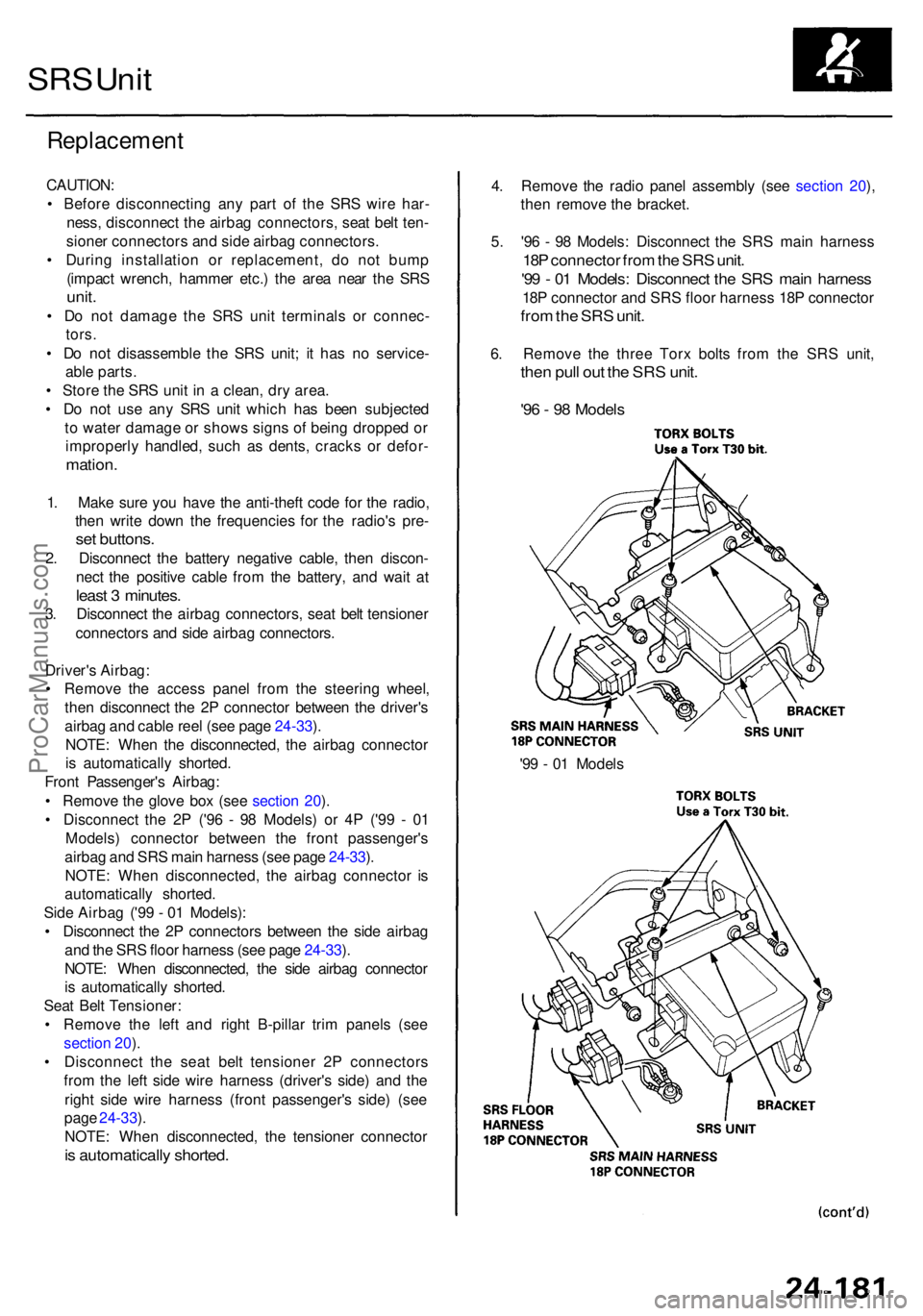
'99 - 0 1 Model s
4
. Remov e th e radi o pane l assembl y (se e sectio n 20 ),
the n remov e th e bracket .
5 . '9 6 - 9 8 Models : Disconnec t th e SR S mai n harnes s
18P connecto r fro m th e SR S unit .
'99 - 0 1 Models : Disconnec t th e SR S mai n harnes s
18P connecto r an d SR S floo r harnes s 18 P connecto r
from th e SR S unit .
6. Remov e th e thre e Tor x bolt s fro m th e SR S unit ,
then pul l ou t th e SR S unit .
'96 - 9 8 Model s
ProCarManuals.com
Page 1953 of 1954
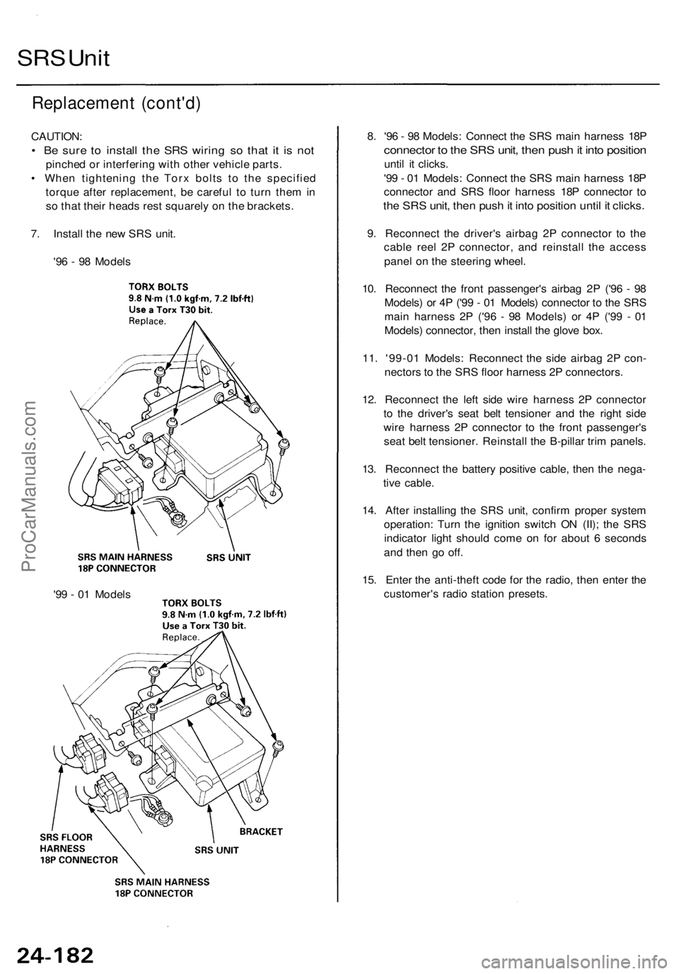
Replacement (cont'd )
CAUTION :
• B e sur e t o instal l th e SR S wirin g s o tha t i t i s no t
pinche d o r interferin g wit h othe r vehicl e parts .
• Whe n tightenin g th e Tor x bolt s t o th e specifie d
torqu e afte r replacement , b e carefu l t o tur n the m in
s o tha t thei r head s res t squarel y o n th e brackets .
7 . Instal l th e ne w SR S unit .
'9 6 - 9 8 Model s
SRS Uni t
8. '9 6 - 9 8 Models : Connec t th e SR S mai n harnes s 18 P
connecto r t o th e SR S unit , the n pus h it int o positio n
until i t clicks .
'9 9 - 0 1 Models : Connec t th e SR S mai n harnes s 18 P
connecto r an d SR S floo r harnes s 18 P connecto r t o
th e SR S unit , the n pus h it int o positio n unti l i t clicks .
9. Reconnec t th e driver' s airba g 2 P connecto r t o th e
cabl e ree l 2 P connector , an d reinstal l th e acces s
pane l o n th e steerin g wheel .
10 . Reconnec t th e fron t passenger' s airba g 2 P ('9 6 - 9 8
Models ) o r 4 P ('9 9 - 0 1 Models ) connecto r t o th e SR S
mai n harnes s 2 P ('9 6 - 9 8 Models ) o r 4 P ('9 9 - 0 1
Models ) connector , the n instal l th e glov e box .
11 . '99-0 1 Models : Reconnec t th e sid e airba g 2 P con -
nector s t o th e SR S floo r harnes s 2 P connectors .
12 . Reconnec t th e lef t sid e wir e harnes s 2 P connecto r
t o th e driver' s sea t bel t tensione r an d th e righ t sid e
wir e harnes s 2 P connecto r t o th e fron t passenger' s
sea t bel t tensioner . Reinstal l th e B-pilla r tri m panels .
13 . Reconnec t th e batter y positiv e cable , the n th e nega -
tiv e cable .
14 . Afte r installin g th e SR S unit , confir m prope r syste m
operation : Tur n th e ignitio n switc h O N (II) ; th e SR S
indicato r ligh t shoul d com e o n fo r abou t 6 second s
an d the n g o off .
15 . Ente r th e anti-thef t cod e fo r th e radio , the n ente r th e
customer' s radi o statio n presets .
'9 9 - 0 1 Model s
ProCarManuals.com