check engine ACURA RL KA9 1996 Service Manual PDF
[x] Cancel search | Manufacturer: ACURA, Model Year: 1996, Model line: RL KA9, Model: ACURA RL KA9 1996Pages: 1954, PDF Size: 61.44 MB
Page 1239 of 1954
Troubleshooting Precaution s
System Indicator s
If th e syste m is OK , th e AB S indicato r goe s of f onc e afte r turnin g th e ignitio n switc h O N (II ) withou t startin g th e engine ,
an d the n com e o n agai n an d g o of f severa l second s late r afte r startin g th e engine . Thi s occur s becaus e th e VS A contro l
uni t i s turne d o n b y th e IG 2 powe r source .
Th e AB S indicato r o r VS A syste m indicato r come s o n whe n th e VS A contro l uni t detect s a proble m in th e system .
Th e AB S indicato r o r VS A syste m indicato r wil l als o com e o n unde r thes e conditions , eve n thoug h th e syste m is oper -
atin g properly :
— Th e vehicl e goe s int o a spi n
— Th e AB S continue s t o operat e fo r a lon g tim e
— Th e vehicl e is subjecte d to a n electrica l signa l disturbanc e
I f ther e is a faul t i n th e PGM-F I system , onl y th e VS A syste m indicato r come s on .
Th e VS A Activatio n Indicato r wil l flas h whe n onl y th e driv e wheel s rotat e o r on e o f th e driv e wheel s is stuck . Whe n thi s
occurs , th e AB S indicato r an d VS A syste m indicato r d o no t com e on .
T o determin e th e actua l caus e o f th e problem , questio n th e custome r abou t th e problem , takin g thes e condition s int o con -
sideration .
Whe n a proble m is detecte d an d th e AB S o r VS A indicato r come s on , ther e ar e case s whe n th e indicato r stay s o n unti l
th e ignitio n switc h i s turne d OFF , an d case s whe n th e indicato r goe s of f automaticall y whe n th e syste m return s t o nor -
mal . Fo r DT C 6 1 an d 62 , th e indicato r goe s of f automaticall y whe n th e syste m return s t o normal . Fo r al l othe r codes ,
th e indicato r stay s o n unti l th e ignitio n switc h is turne d OFF .
Fo r DTC s 12 , 14 , 16 , 18 , 51 , 52 , 53 , 66 , 6 8 an d 84 , th e AB S indicato r goe s of f whe n th e vehicl e is drive n agai n an d th e
syste m is O K afte r th e ignitio n switc h is turne d fro m OF F to O N (II) . However , i f th e DT C is cleared , th e CP U reset s an d
th e indicato r goe s of f righ t afte r th e engin e is starte d if th e syste m is OK .
Th e AB S is no t operationa l whe n th e AB S indicato r i s ON ; th e VS A is no t operationa l whe n th e VS A indicato r i s ON .
Whe n th e VS A indicato r an d MI L ar e bot h ON , troubleshoo t th e PGM-F I syste m first .
Diagnosti c Troubl e Cod e (DTC )
Th e memor y ca n hol d an y numbe r o f DTCs . However , whe n th e sam e DT C is detecte d mor e tha n once , th e mor e recen t
DT C is writte n ove r th e earlie r one . Therefore , whe n th e sam e proble m is detecte d repeatedly , i t i s memorize d a s a sin -
gle DTC .
The DTC s ar e indicate d in ascendin g numbe r order , no t i n th e orde r the y occur .
Th e DTC s ar e memorize d in th e EEPRO M (non-volatil e memory) . Therefore , th e memorize d DTC s canno t b e cancele d
b y disconnectin g th e battery . Perfor m th e specifie d procedure s to clea r th e DTCs .
Self-diagnosi s
Self-diagnosis can be classifie d int o tw o categories :
— Initia l diagnosis : Performe d righ t afte r th e engin e start s an d unti l th e AB S o r VS A indicato r goe s off .
— Regula r diagnosis : Performe d righ t afte r th e initia l diagnosi s unti l th e ignitio n switc h is turne d OFF .
When a proble m is detecte d b y self-diagnosis , th e VS A contro l uni t shift s to fail-saf e mode .
Kickbac k
The pum p moto r operate s whe n th e AB S is functioning , an d th e flui d in th e reservoi r i s force d ou t t o th e maste r cylinder ,
causing kickbac k a t th e brak e pedal .
Pum p Moto r
Th e pum p moto r operate s whe n th e AB S is functioning .
The VS A contro l uni t check s th e pum p moto r operatio n durin g initia l diagnosi s whe n th e vehicl e is started .
You ma y hea r th e moto r operat e a t thi s time , bu t i t i s normal .
Brak e Flui d Replacement/Ai r Bleedin g
Brak e flui d replacemen t an d ai r bleedin g procedure s ar e identica l t o th e procedure s us e o n vehicle s no t equippe d wit h
VSA . T o eas e bleeding , star t wit h th e fron t wheels .
ProCarManuals.com
Page 1256 of 1954
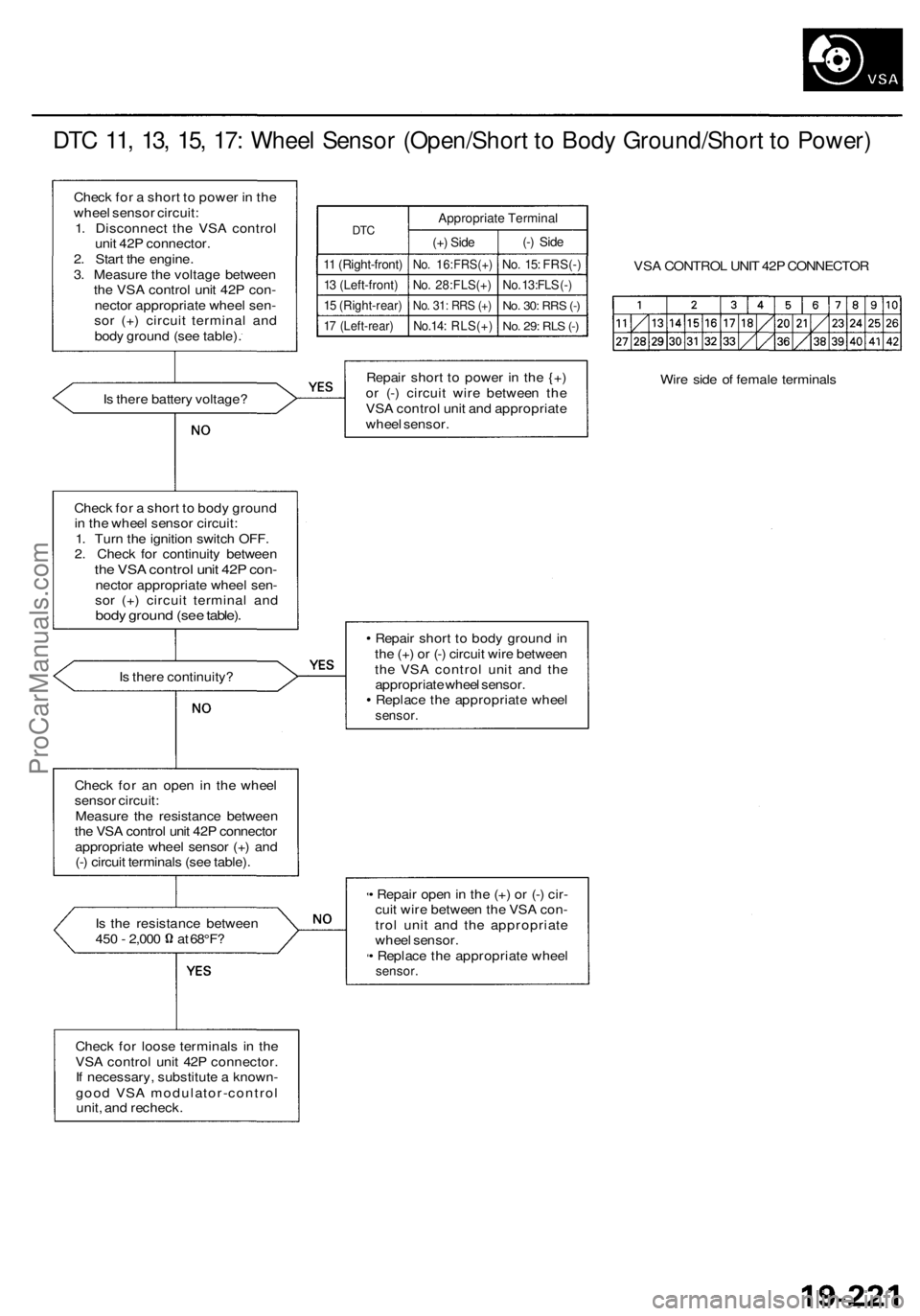
DTC 11, 13, 15, 17: Wheel Sensor (Open/Short to Body Ground/Short to Power)
Check for a short to power in the
wheel sensor circuit:
1. Disconnect the VSA control
unit 42P connector.
2. Start the engine.
3. Measure the voltage between
the VSA control unit 42P con-
nector appropriate wheel sen-
sor (+) circuit terminal and
body ground (see table).
DTC
11 (Right-front)
13 (Left-front)
15 (Right-rear)
17 (Left-rear)
Appropriate Terminal
(+) Side
No. 16:FRS(+)
No. 28:FLS(+)
No. 31: RRS (+)
No.14: RLS(+)
(-) Side
No. 15: FRS(-)
No. 13:FLS (-)
No. 30:
RRS
(-)
No. 29: RLS (-)
VSA CONTROL UNIT 42P CONNECTOR
Is there battery voltage?
Repair short to power in the {+)
or (-) circuit wire between the
VSA control unit and appropriate
wheel sensor.
Wire side of female terminals
Check for a short to body ground
in the wheel sensor circuit:
1. Turn the ignition switch OFF.
2. Check for continuity between
the VSA control unit 42P con-
nector appropriate wheel sen-
sor (+) circuit terminal and
body ground (see table).
Is there continuity?
Repair short to body ground in
the (+) or (-) circuit wire between
the VSA control unit and the
appropriate wheel sensor.
Replace the appropriate wheel
sensor.
Check for an open in the wheel
sensor circuit:
Measure the resistance between
the VSA control unit 42P connector
appropriate wheel sensor (+) and
(-) circuit terminals (see table).
Is the resistance between
450 - 2,000 at 68°F?
• Repair open in the (+) or (-) cir-
cuit wire between the VSA con-
trol unit and the appropriate
wheel sensor.
• Replace the appropriate wheel
sensor.
Check for loose terminals in the
VSA control unit 42P connector.
If necessary, substitute a known-
good VSA modulator-control
unit, and recheck.ProCarManuals.com
Page 1271 of 1954
Troubleshooting
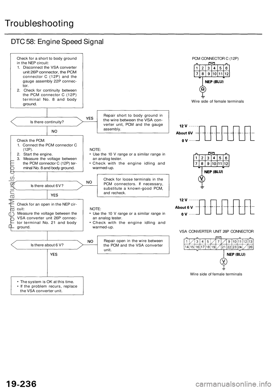
DTC 58: Engine Speed Signal
Check for a short to body ground
in the NEP circuit:
1. Disconnect the VSA converter
unit 26P connector, the PCM
connector C (12P) and the
gauge assembly 22P connec-
tor.
2. Check for continuity between
the PCM connector C (12P)
terminal No. 8 and body
ground.
Is there continuity?
Check the PCM:
1. Connect the PCM connector C
(12P).
2. Start the engine.
3. Measure the voltage between
the PCM connector C (12P) ter-
minal No. 8 and body ground.
Is there about 6V?
Check for an open in the NEP cir-
cuit:
Measure the voltage between the
VSA converter unit 26P connec-
tor terminal No. 21 and body
ground.
Is there about 6 V?
The system is OK at this time.
If the problem recurs, replace
the VSA converter unit.
PCM CONNECTOR C (12P)
Wire side of female terminals
Repair short to body ground in
the wire between the VSA con-
verter unit, PCM and the gauge
assembly.
NOTE:
Use the 10 V range or a similar range in
an analog tester.
Check with the engine idling and
warmed-up.
Check for loose terminals in the
PCM connectors. If necessary,
substitute a known-good PCM,
and recheck.
NOTE:
Use the 10 V range or a similar range in
an analog tester.
Check with the engine idling and
warmed-up.
VSA CONVERTER UNIT 26P CONNECTOR
Repair open in the wire between
the PCM and the VSA converter
unit.
Wire side of female terminalsProCarManuals.com
Page 1283 of 1954
Troubleshooting
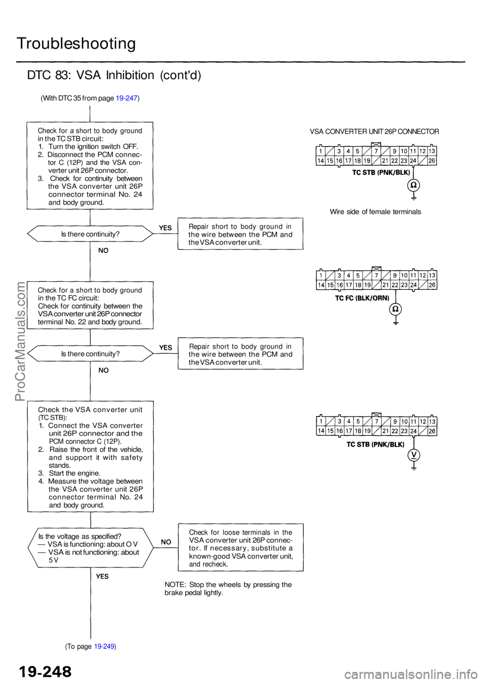
DTC 83 : VS A Inhibitio n (cont'd )
(With DT C 35 fro m pag e 19-247 )
Check fo r a shor t t o bod y groun din th e T C ST B circuit :
1 . Tur n th e ignitio n switc h OFF .
2 . Disconnec t th e PC M connec -
tor C (12P ) and th e VS A con -verte r uni t 26 P connector .
3 . Chec k fo r continuit y betwee n
th e VS A converte r uni t 26 P
connecto r termina l No . 2 4an d bod y ground .
I s ther e continuity ?
Check fo r a shor t t o bod y groun din th e T C F C circuit :
Chec k fo r continuit y betwee n th e
VS A converte r uni t 26 P connecto rterminal No . 2 2 an d bod y ground .
I s ther e continuity ?
Chec k the VSA converte r uni t
(TC STB) :1. Connec t th e VS A converte runit 26 P connecto r an d th ePC M connecto r C (12P) .2. Rais e th e fron t o f th e vehicle ,
an d suppor t i t wit h safet y
stands.3. Star t th e engine .
4 . Measur e th e voltag e betwee n
th e VS A converte r uni t 26 P
connecto r termina l No . 2 4
an d bod y ground .
I s th e voltag e a s specified ?
— VS A is functioning : abou t O V
— VS A is no t functioning : abou t5V
(T o pag e 19-249 )
VSA CONVERTE R UNI T 26 P CONNECTO R
Wire sid e o f femal e terminal s
Repair shor t t o bod y groun d i nth e wir e betwee n th e PC M an d
th e VS A converte r unit .
Repai r shor t t o bod y groun d i nth e wir e betwee n th e PC M an d
th e VS A converte r unit .
Chec k fo r loos e terminal s i n th eVS A converte r uni t 26 P connec -
tor . I f necessary , substitut e a
known-goo d VS A converte r unit ,
and recheck .
NOTE: Sto p th e wheel s b y pressin g th e
brak e peda l lightly .
ProCarManuals.com
Page 1304 of 1954

VSA Modulator-Control Unit
Removal/Installation
NOTE:
Do not spill brake fluid on the vehicle; it may damage the paint; if brake fluid does contact the paint, wash it off imme-
diately with water.
Take care not to damage or deform the brake lines during removal and installation.
To prevent the brake fluid from flowing, plug and cover the hose ends and joints with a shop towel or equivalent material.
Removal
1. Disconnect the pressure sensor 3P connector.
2. Pull the locking lever of the VSA control unit 42P connec-
tor up, then disconnect the connector.
3. Disconnect the six brake lines.
4. Remove the two 8 mm nuts.
5. Remove the VSA modulator-control unit.
Installation
1. Install the VSA modulator-control unit, then tighten the
two 8 mm nuts.
2. Align the connecting surfaces of the VSA control unit 42P
connector.
3. Push the locking lever of the VSA control unit 42P connec-
tor down until you hear a click.
4. Connect the pressure sensor 3P connector.
5. Connect the six brake lines.
6. Perform the precharge brake line bleeding (see page 19-
271).
7. Bleed the brake system, starting with the front wheels.
8. Start the engine, and check that the ABS indicator goes
off.
9. Test-drive the vehicle, and check that the ABS indicator
does not come on.
To right-rear
To left-rear
PRESSURE SENSOR
3P CONNECTOR
VSA MODULATOR
CONTROL UNIT
LOCKING LEVER
VSA CONTROL UNIT
42P CONNECTOR
To right-front
To left-front
FLARE NUT
15 N-m (1.5 kgf-m, 11 Ibf-ft)
MOUNTING BOLT
VSA CONTROL UNIT 42P CONNECTOR
8 mm BOLT
22 N-m (2.2 kgf-m, 16 Ibf-ft)
8 mm NUT
9 N-m (0.9 kgf-m, 7 Ibf-ft)
RUBBER MOUNT
BRACKETProCarManuals.com
Page 1451 of 1954
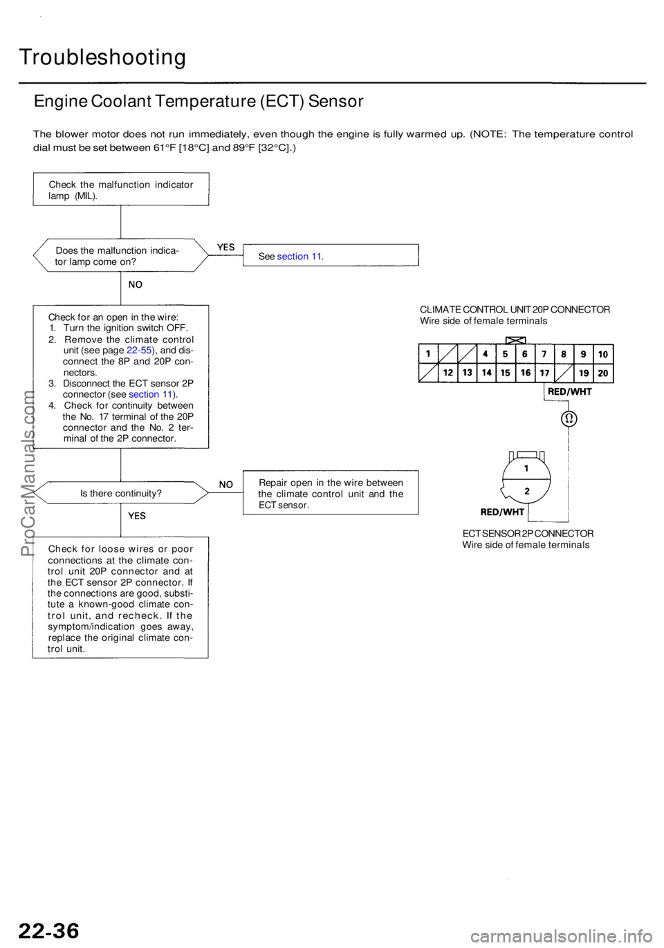
Troubleshooting
Engine Coolan t Temperatur e (ECT ) Senso r
The blowe r moto r doe s no t ru n immediately , eve n thoug h th e engin e is full y warme d up . (NOTE : Th e temperatur e contro l
dia l mus t b e se t betwee n 61° F [18°C ] an d 89° F [32°C]. )
Does th e malfunctio n indica -
to r lam p com e on ?
Chec k fo r a n ope n in th e wire :
1 . Tur n th e ignitio n switc h OFF .
2 . Remov e th e climat e contro l
uni t (se e pag e 22-55 ), an d dis -
connec t th e 8 P an d 20 P con -
nectors .
3 . Disconnec t th e EC T senso r 2 P
connecto r (se e sectio n 11 ).
4 . Chec k fo r continuit y betwee n
th e No . 1 7 termina l o f th e 20 P
connecto r an d th e No . 2 ter -
mina l o f th e 2 P connector .
I s ther e continuity ?
Chec k fo r loos e wire s o r poo r
connection s a t th e climat e con -trol uni t 20 P connecto r an d a t
th e EC T senso r 2 P connector . I f
th e connection s ar e good , substi -
tut e a known-goo d climat e con -
trol unit , an d recheck . I f th esymptom/indicatio n goe s away ,
replac e th e origina l climat e con -
tro l unit . Se
e sectio n 11 .
CLIMATE CONTRO L UNI T 20 P CONNECTO R
Wir e sid e o f femal e terminal s
Repai r ope n in th e wir e betwee n
th e climat e contro l uni t an d th e
EC T sensor .
ECT SENSO R 2P CONNECTO R
Wir e side of femal e terminal s
Chec
k th e malfunctio n indicato r
lam p (MIL) .
ProCarManuals.com
Page 1462 of 1954
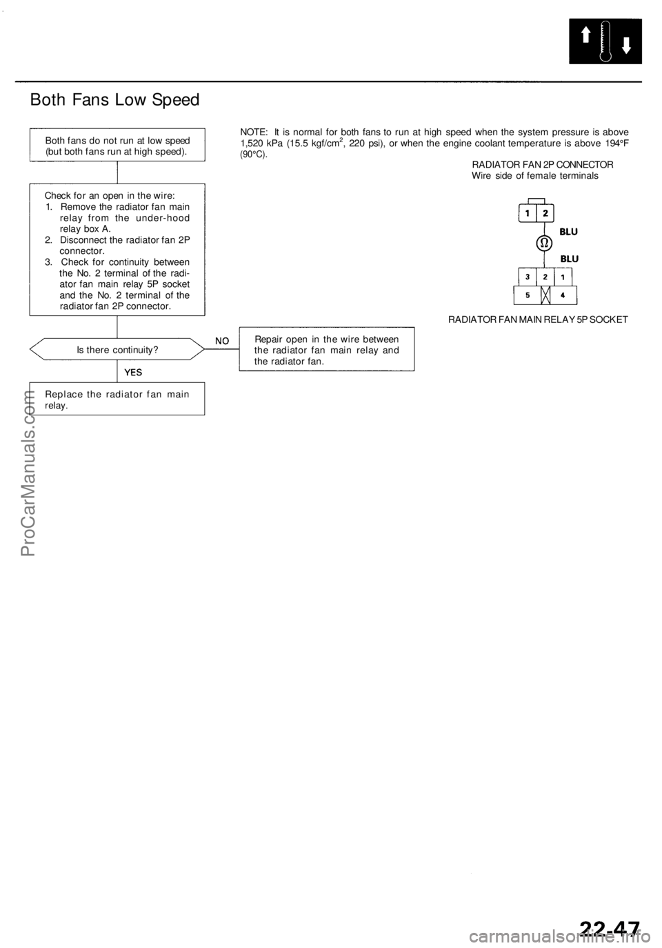
Both Fans Low Speed
Both fans do not run at low speed
(but both fans run at high speed).
Check for an open in the wire:
1. Remove the radiator fan main
relay from the under-hood
relay box A.
2. Disconnect the radiator fan 2P
connector.
3. Check for continuity between
the No. 2 terminal of the radi-
ator fan main relay 5P socket
and the No. 2 terminal of the
radiator fan 2P connector.
NOTE: It is normal for both fans to run at high speed when the system pressure is above
1,520 kPa (15.5 kgf/cm2, 220 psi), or when the engine coolant temperature is above 194°F
(90°C).
RADIATOR FAN 2P CONNECTOR
Wire side of female terminals
RADIATOR FAN MAIN RELAY 5P SOCKET
Is there continuity?
Repair open in the wire between
the radiator fan main relay and
the radiator fan.
Replace the radiator fan main
relay.ProCarManuals.com
Page 1466 of 1954
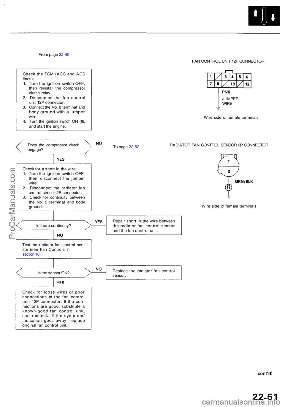
From pag e 22-4 9
Chec k th e PC M (AC C an d AC S
lines) :1. Tur n th e ignitio n switc h OFF ,then reinstal l th e compresso r
clutc h relay .
2 . Disconnec t th e fa n contro l
uni t 12 P connector .
3 . Connec t th e No . 8 termina l an d
bod y groun d wit h a jumpe rwire.
4 . Tur n th e ignitio n switc h O N (II) ,
an d star t th e engine .
Doe s th e compresso r clutc h
engage ?
Is ther e continuity ?
Test th e radiato r fa n contro l sen -
so r (se e Fa n Control s i n
section 10 ).
Is th e senso r OK ?
Chec k fo r loos e wire s o r poo r
connection s a t th e fa n contro l
uni t 12 P connector . I f th e con -
nection s ar e good , substitut e a
known-goo d fa n contro l unit ,
an d recheck . I f th e symptom /
indicatio n goe s away , replac e
origina l fa n contro l unit . FA
N CONTRO L UNI T 12 P CONNECTO R
T o pag e 22-5 2 Wir
e sid e o f femal e terminal s
RADIATO R FA N CONTRO L SENSO R 2 P CONNECTO R
Wir e sid e o f femal e terminal s
Repai r shor t i n th e wir e betwee n
th e radiato r fa n contro l senso r
an d th e fa n contro l unit .
Replac e th e radiato r fa n contro lsensor.
Check fo r a shor t i n th e wire :1. Tur n th e ignitio n switc h OFF ,then disconnec t th e jumpe rwire.2. Disconnec t th e radiato r fa n
contro l senso r 2 P connector .
3 . Chec k fo r continuit y betwee n
th e No . 2 termina l an d bod y
ground . JUMPE
R
WIRE
ProCarManuals.com
Page 1595 of 1954
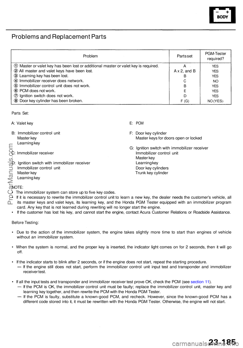
Problems an d Replacemen t Part s
Proble m
Master o r vale t ke y ha s bee n los t o r additiona l maste r o r vale t ke y is required .
Al l maste r an d vale t key s hav e bee n lost .
Learnin g ke y ha s bee n lost .
Immobilize r receive r doe s network .
Immobilize r contro l uni t doe s no t work .
PC M doe s no t work .
Ignitio n switc h doe s no t work .
Doo r ke y cylinde r ha s bee n broken . Part
s se t
PGM-Teste r
required?
YES
YES
YE S
NO
YE S
YE S
YES
NO (YES )
A
A x 2 , an d B
B
C
B
E
D
F (G )
Part s Set :
A: Vale t ke y
B : Immobilize r contro l uni t
Maste r ke y
Learnin g ke y
C : Immobilize r receive r
D : Ignitio n switc h wit h immobilize r receive r
Immobilize r contro l uni t
Maste r ke y
Learnin g ke yE: PC M
F: Doo r ke y cylinde r
Maste r key s fo r door s ope n o r locke d
G : Ignitio n switc h wit h immobilize r receive r
Immobilize r contro l uni t
Maste r ke y
Learnin g ke y
Doo r ke y cylinder s
Trun k ke y cylinde r
NOTE:
• Th e immobilize r syste m ca n stor e u p to fiv e ke y codes .
• I f i t i s necessar y t o rewrit e th e immobilize r contro l uni t t o lear n a ne w key , th e deale r need s th e customer' s vehicle , al l
it s maste r key s an d vale t keys , it s learnin g key , an d th e Hond a PG M Teste r equippe d wit h a n immobilize r progra m
card . An y ke y tha t i s no t learne d durin g rewritin g wil l n o longe r star t th e engine .
• I f th e custome r ha s los t hi s key , an d canno t star t th e engine , contac t Acur a Custome r Relation s o r Roadsid e Assistance .
Before Testing :
• Du e t o th e actio n o f th e immobilize r system , th e engin e take s slightl y mor e tim e t o star t tha n engine s o f vehicl e
withou t a n immobilize r system .
• Whe n th e syste m is normal , an d th e prope r ke y i s inserted , th e indicato r ligh t come s o n fo r 2 seconds , the n i t wil l g o
off .
• I f th e indicato r start s t o blin k afte r 2 seconds , o r i f th e engin e doe s no t start , repea t th e startin g procedure .
If th e engin e stil l doe s no t start , perfor m th e immobilize r contro l uni t inpu t tes t an d transponde r an d immobilize r
receive r test .
• I f al l th e inpu t test s an d transponde r an d immobilize r receive r tes t prov e OK , chec k th e PC M (se e sectio n 11 ).
I f th e PC M is OK , th e immobilize r contro l uni t mus t b e faulty ; replac e th e immobilize r contro l unit , maste r ke y an d
learnin g ke y together , an d the n rewrit e th e PC M wit h th e Hond a PG M Tester .
If th e PC M is faulty , substitut e a known-goo d PCM , an d recheck . However , sinc e th e known-goo d PC M ha s a
differen t cod e store d int o it , i t mus t b e rewritte n wit h th e Hond a PG M Tester . Otherwise , th e engin e wil l no t start .
ProCarManuals.com
Page 1858 of 1954
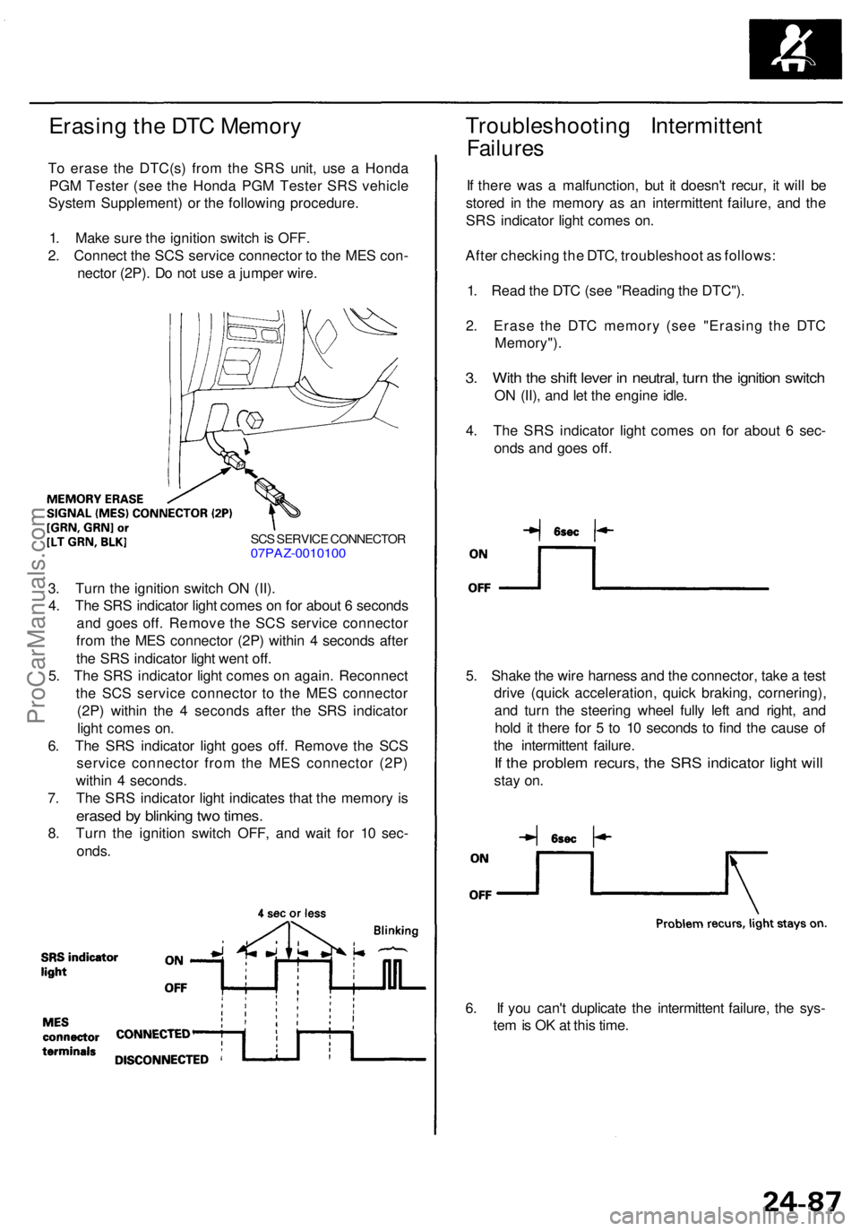
Erasing th e DT C Memor y
To eras e th e DTC(s ) fro m th e SR S unit , us e a Hond a
PG M Teste r (se e th e Hond a PG M Teste r SR S vehicl e
Syste m Supplement ) o r th e followin g procedure .
1 . Mak e sur e th e ignitio n switc h is OFF .
2 . Connec t th e SC S servic e connecto r t o th e ME S con -
necto r (2P) . D o no t us e a jumpe r wire .
Troubleshootin g Intermitten t
Failures
If ther e wa s a malfunction , bu t i t doesn' t recur , i t wil l b e
store d i n th e memor y a s a n intermitten t failure , an d th e
SR S indicato r ligh t come s on .
Afte r checkin g th e DTC , troubleshoo t a s follows :
1 . Rea d th e DT C (se e "Readin g th e DTC") .
2 . Eras e th e DT C memor y (se e "Erasin g th e DT C
Memory") .
3. Wit h th e shif t leve r i n neutral , tur n th e ignitio n switc h
ON (II) , an d le t th e engine idle.
4 . Th e SR S indicato r ligh t come s o n fo r abou t 6 sec -
ond s an d goe s off .
SCS SERVIC E CONNECTO R07PAZ-001010 0
3. Tur n th e ignitio n switc h O N (II) .
4 . Th e SR S indicato r ligh t come s o n fo r abou t 6 second s
an d goe s off . Remov e th e SC S servic e connecto r
fro m th e ME S connecto r (2P ) withi n 4 second s afte r
th e SR S indicato r ligh t wen t off .
5 . Th e SR S indicato r ligh t come s o n again . Reconnec t
th e SC S servic e connecto r t o th e ME S connecto r
(2P ) withi n th e 4 second s afte r th e SR S indicato r
ligh t come s on .
6 . Th e SR S indicato r ligh t goe s off . Remov e th e SC S
servic e connecto r fro m th e ME S connecto r (2P )
withi n 4 seconds .
7 . Th e SR S indicato r ligh t indicate s tha t th e memor y i s
erase d b y blinkin g tw o times .
8. Tur n th e ignitio n switc h OFF , an d wai t fo r 1 0 sec -
onds . 5
. Shak e th e wir e harnes s an d th e connector , tak e a tes t
driv e (quic k acceleration , quic k braking , cornering) ,
an d tur n th e steerin g whee l full y lef t an d right , an d
hol d i t ther e fo r 5 to 1 0 second s t o fin d th e caus e o f
th e intermitten t failure .
If th e proble m recurs , th e SR S indicato r ligh t wil l
stay on .
6 . I f yo u can' t duplicat e th e intermitten t failure , th e sys -
te m is O K a t thi s time .
ProCarManuals.com