check engine ACURA RL KA9 1996 Service Service Manual
[x] Cancel search | Manufacturer: ACURA, Model Year: 1996, Model line: RL KA9, Model: ACURA RL KA9 1996Pages: 1954, PDF Size: 61.44 MB
Page 661 of 1954
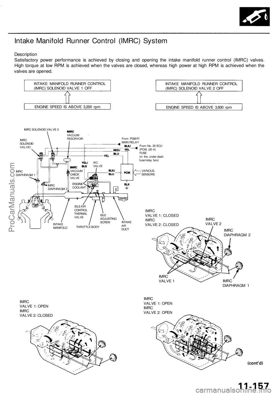
Intake Manifol d Runne r Contro l (IMRC ) Syste m
Descriptio n
Satisfactor y powe r performanc e i s achieve d b y closin g an d openin g th e intak e manifol d runne r contro l (IMRC ) valves .
Hig h torqu e a t lo w RP M is achieve d whe n th e valve s ar e closed , wherea s hig h powe r a t hig h RP M is achieve d whe n th e
valve s ar e opened .
INTAKE MANIFOL D RUNNE R CONTRO L
(IMRC ) SOLENOI D VALV E 1 OF F INTAK
E MANIFOL D RUNNE R CONTRO L
(IMRC ) SOLENOI D VALV E 2 OF F
ENGIN E SPEE D IS ABOV E 3,20 0 rp m
ENGINE SPEE D IS ABOV E 3,80 0 rp m
IMR C SOLENOI D VALV E 2
IMR C
SOLENOI D
VALVE !
IMR C
DIAPHRAG M 1
VARIOU SSENSOR S
IMRC
VALVE 1: CLOSED IMRC
VALVE 2: CLOSED
IMR C
VALV E 2
IMR C
DIAPHRAG M 2
IMR C
VALV E 1 IMR
C
DIAPHRAG M 1
IMR C
VALV E 1 : OPE N
IMR C
VALV E 2 : CLOSE D IMR
C
VALV E 1 : OPE N
IMR C
VALV E 2 : OPE N
From No . 2 0 EC U(PCM ) (20 A )FUS E
(i n th e under-das h
fuse/rela y box )
Fro
m PGM-F I
MAI N RELA Y
IACVALV E
ENGIN ECOOLAN T
VACUU
M
RESORVOI R
IMRC
DIAPHRAG M 2 VACUU
M
CHECKVALV E
INTAK E
MANIFOL DTHROTTL
E BOD Y
IDL
E AI R
CONTRO L
THERMA L
VALVEIDLEADJUSTIN GSCREWINTAK EAIRDUC T
ProCarManuals.com
Page 712 of 1954
Description
The automatic transmission is a combination of a 3-element torque converter and a dual-shaft electronically controlled
automatic transmission which provides 4 speeds forward and 1 reverse. The entire unit is positioned in line with the engine.
Torque Converter, Gears and Clutches
The torque converter consists of a pump, turbine and stator, assembled in a single unit. They are connected to the engine
crankshaft so they turn together as a unit as the engine turns. Around the outside of the drive plate is a ring gear which
meshes with the starter pinion when the engine is being started.
The entire torque converter assembly serves as a flywheel while transmitting power to the transmission mainshaft.
The transmission has two parallel shafts: the mainshaft and the countershaft. The mainshaft is in line with the engine
crankshaft. The mainshaft includes the 1st, 4th and 2nd clutches and gears for 4th, 1st, 2nd and reverse (3rd gear is integral
with the mainshaft). The countershaft includes the 3rd, 1st-hold and reverse clutches, and gears for 3rd, 4th, 1st, 2nd,
reverse and park. The secondary drive gear is integrated with the countershaft. The gears on the mainshaft are in constant
mesh with those on the countershaft. When certain combinations of gears in the transmission are engaged by clutches,
power is transmitted from the mainshaft to the countershaft to provide , , , and positions.
Electronic Control
The electronic control system consists of a Powertrain Control Module (PCM), sensors, a A/T clutch pressure control solenoid
and four solenoid valves. Shifting and lock-up are electronically controlled for comfortable driving under all conditions.
The PCM is located below the dashboard, under the front lower panel on the passenger's side.
Hydraulic Control
The lower valve body assembly includes the main valve body, the secondary valve body, the throttle valve body, the
solenoid, the shift solenoid valves and the ATF passage body. They are bolted on the lower part of the transmission hous-
ing. Other valve bodies, the regulator valve body, the ATF pump body and the accumulator body, are bolted to the torque
converter housing.
The main valve body contains the manual valve, the 1-2 shift valve, the 2-3 shift valve, the 3-4 shift valve, the 4-3 kick-down
valve and the main orifice control valve. The secondary valve body contains the 3-4 orifice control valve, the 4-3 shift timing
valve, the line pressure control valve, the modulator valve and the accumulator pistons. The throttle valve body includes
the throttle valve which is bolted onto the secondary valve body. The A/T clutch pressure control solenoid is joined to the
throttle valve body. The regulator valve body contains the regulator valve, the lock-up shift valve and the cooler relief valve.
Fluid from the regulator passes through the manual valve to the various control valves. The ATF pump body contains the
lock-up timing valve, the lock-up control valve and the relief valve. The torque converter check valve is located in the torque
converter housing under the ATF pump body. The accumulator body contains the accumulator pistons. The reverse accu-
mulator and the 1st-hold accumulator pistons are assembled in the rear cover.
The 1st, 1st-hold, 2nd and reverse clutches receive fluid from their respective feed pipes, and the 3rd and 4th clutches
receive fluid from the internal hydraulic circuit.
Shift Control Mechanism
Input from various sensors located throughout the vehicle determines which shift solenoid valve the PCM will activate.
Activating a shift solenoid valve changes modulator pressure, causing a shift valve to move. This pressurizes a line to one
of the clutches, engaging the clutch and its corresponding gear.
Lock-up Mechanism
In position, in 2nd, 3rd, and 4th, and position in 3rd, pressurized fluid is drained from the back of the torque con-
verter through a fluid passage, causing the lock-up piston to be held against the torque converter cover. As this takes
place, the mainshaft rotates at the same speed as the engine crankshaft. Together with hydraulic control, the PCM opti-
mizes the timing of the lock-up mechanism. The lock-up valves control the range of lock-up according to torque converter
clutch (lock-up control) solenoid valves A and B, and throttle valve. When torque converter clutch (lock-up control)
solenoid valves A and B activate, modulator pressure changes. The torque converter clutch (lock-up control) solenoid
valves A and B are mounted on the torque converter housing, and are controlled by the PCM.ProCarManuals.com
Page 728 of 1954
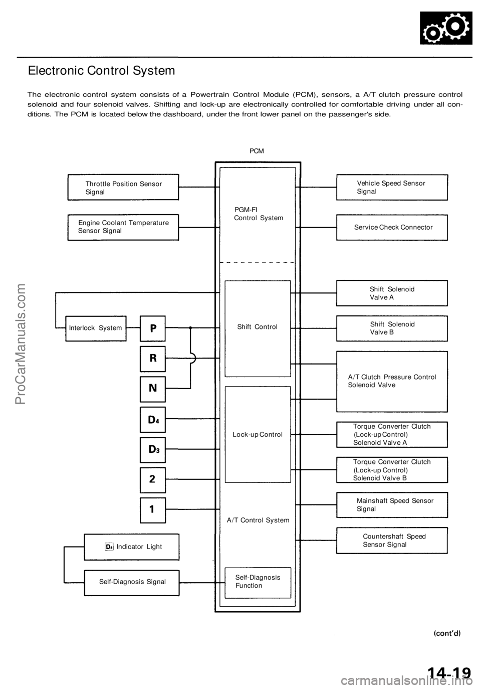
Electronic Control System
The electronic control system consists of a Powertrain Control Module (PCM), sensors, a A/T clutch pressure control
solenoid and four solenoid valves. Shifting and lock-up are electronically controlled for comfortable driving under all con-
ditions. The PCM is located below the dashboard, under the front lower panel on the passenger's side.
PCM
Throttle Position Sensor
Signal
Engine Coolant Temperature
Sensor Signal
Indicator Light
Self-Diagnosis Signal
PGM-FI
Control System
Shift Control
Lock-up Control
A/T Control System
Self-Diagnosis
Function
Vehicle Speed Sensor
Signal
Service Check Connector
Shift Solenoid
Valve A
Shift Solenoid
Valve B
A/T Clutch Pressure Control
Solenoid Valve
Torque Converter Clutch
(Lock-up Control)
Solenoid Valve A
Torque Converter Clutch
(Lock-up Control)
Solenoid Valve B
Mainshaft Speed Sensor
Signal
Countershaft Speed
Sensor Signal
Interlock SystemProCarManuals.com
Page 738 of 1954
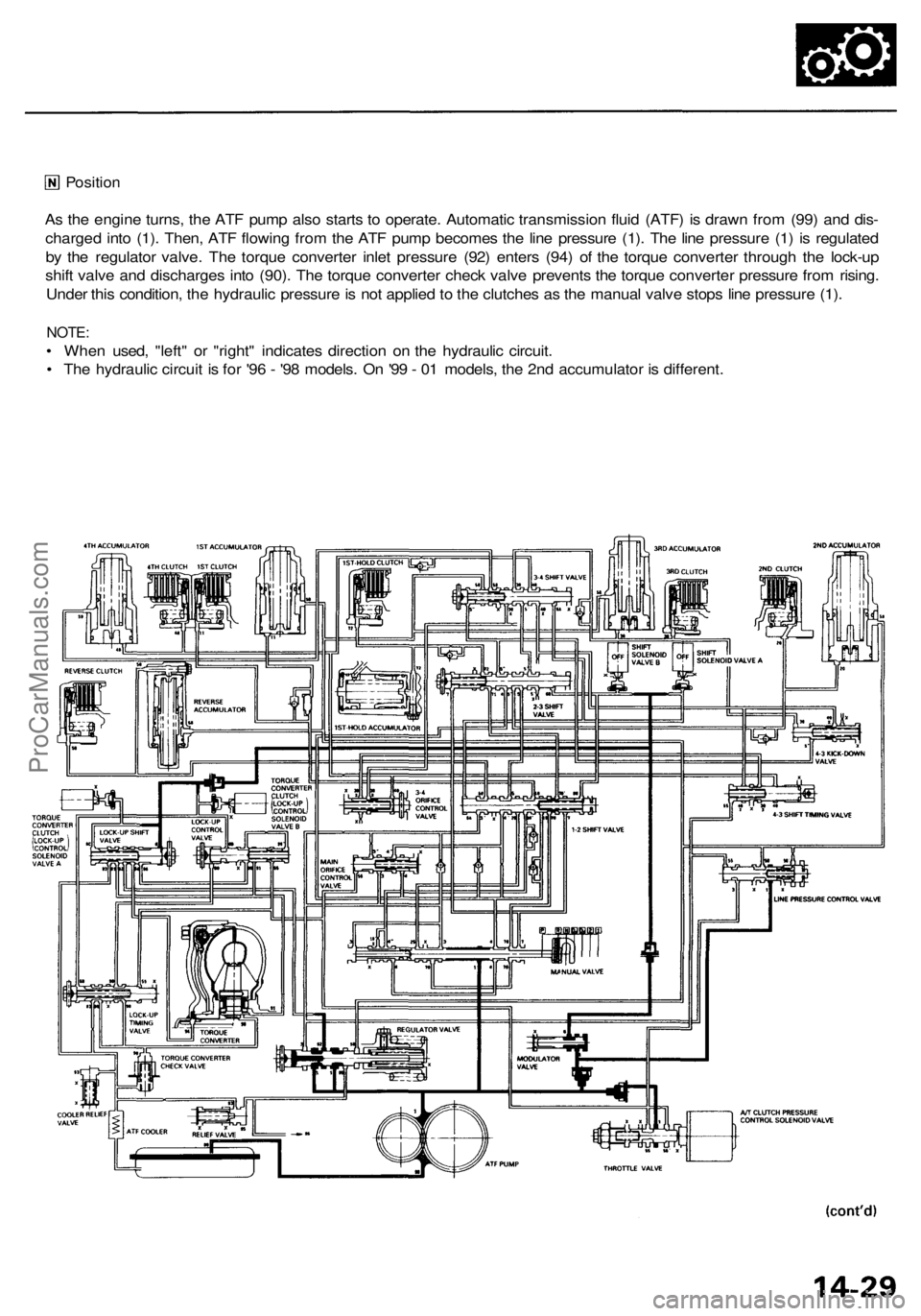
Position
As the engine turns, the ATF pump also starts to operate. Automatic transmission fluid (ATF) is drawn from (99) and dis-
charged into (1). Then, ATF flowing from the ATF pump becomes the line pressure (1). The line pressure (1) is regulated
by the regulator valve. The torque converter inlet pressure (92) enters (94) of the torque converter through the lock-up
shift valve and discharges into (90). The torque converter check valve prevents the torque converter pressure from rising.
Under this condition, the hydraulic pressure is not applied to the clutches as the manual valve stops line pressure (1).
NOTE:
• When used, "left" or "right" indicates direction on the hydraulic circuit.
• The hydraulic circuit is for '96 - '98 models. On '99 - 01 models, the 2nd accumulator is different.ProCarManuals.com
Page 802 of 1954
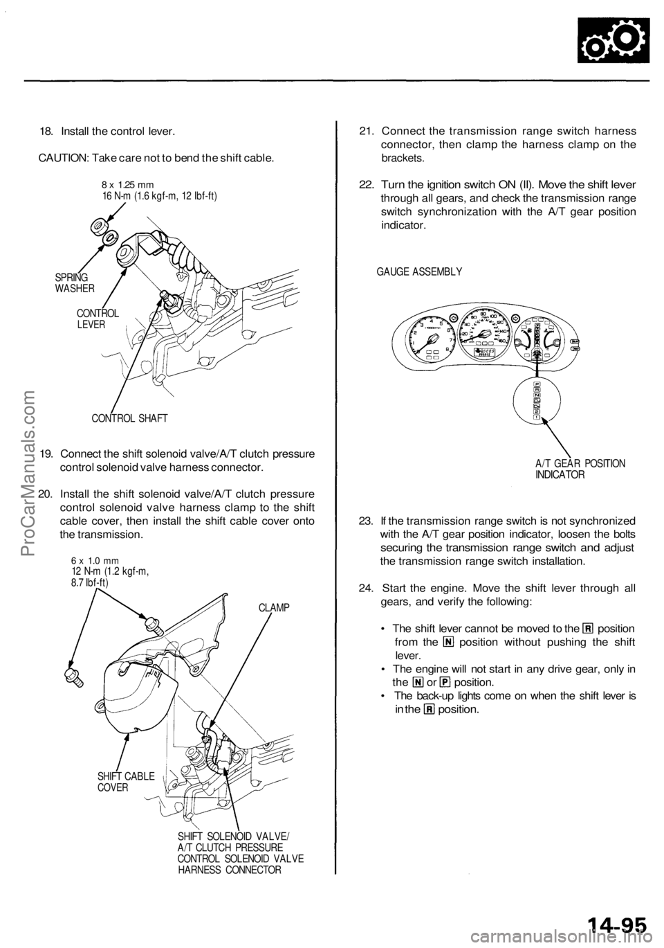
18. Install the control lever.
CAUTION: Take care not to bend the shift cable.
SPRING
WASHER
CONTROL SHAFT
19. Connect the shift solenoid valve/A/T clutch pressure
control solenoid valve harness connector.
20. Install the shift solenoid valve/A/T clutch pressure
control solenoid valve harness clamp to the shift
cable cover, then install the shift cable cover onto
the transmission.
CLAMP
SHIFT CABLE
COVER
SHIFT SOLENOID VALVE/
A/T CLUTCH PRESSURE
CONTROL SOLENOID VALVE
HARNESS CONNECTOR
21. Connect the transmission range switch harness
connector, then clamp the harness clamp on the
brackets.
22. Turn the ignition switch ON (II). Move the shift lever
through all gears, and check the transmission range
switch synchronization with the A/T gear position
indicator.
GAUGE ASSEMBLY
A/T GEAR POSITION
INDICATOR
23. If the transmission range switch is not synchronized
with the A/T gear position indicator, loosen the bolts
securing the transmission range switch and adjust
the transmission range switch installation.
24. Start the engine. Move the shift lever through all
gears, and verify the following:
• The shift lever cannot be moved to the position
from the position without pushing the shift
lever.
• The engine will not start in any drive gear, only in
the or position.
• The back-up lights come on when the shift lever is
in the position.
8 x
1.25
mm
16 N-m (1.6 kgf-m, 12 Ibf-ft)
CONTROL
LEVER
6 x 1.0 mm
12 N-m (1.2 kgf-m,
8.7 Ibf-ft)ProCarManuals.com
Page 815 of 1954
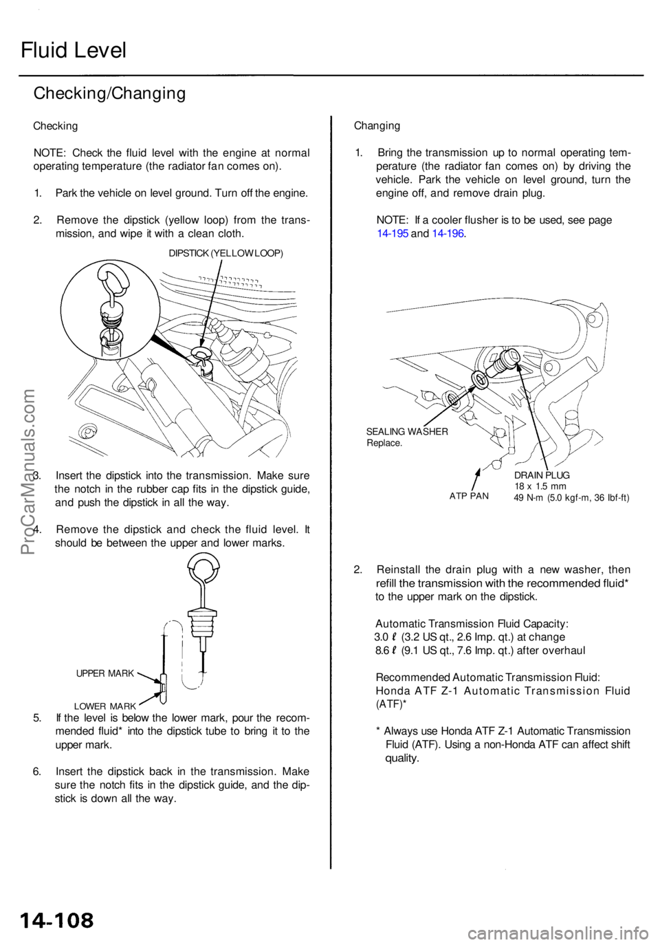
Fluid Leve l
Checking/Changin g
Checking
NOTE: Chec k th e flui d leve l wit h th e engin e a t norma l
operatin g temperatur e (th e radiato r fa n come s on) .
1 . Par k th e vehicl e o n leve l ground . Tur n of f th e engine .
2 . Remov e th e dipstic k (yello w loop ) fro m th e trans -
mission , an d wip e it wit h a clea n cloth .
DIPSTIC K (YELLO W LOOP )
3. Inser t th e dipstic k int o th e transmission . Mak e sur e
th e notc h i n th e rubbe r ca p fit s i n th e dipstic k guide ,
an d pus h th e dipstic k i n al l th e way .
4 . Remov e th e dipstic k an d chec k th e flui d level . I t
shoul d b e betwee n th e uppe r an d lowe r marks .
UPPER MAR K
5. I f th e leve l i s belo w th e lowe r mark , pou r th e recom -
mende d fluid * int o th e dipstic k tub e t o brin g i t t o th e
uppe r mark .
6 . Inser t th e dipstic k bac k i n th e transmission . Mak e
sur e th e notc h fit s i n th e dipstic k guide , an d th e dip -
stic k i s dow n al l th e way .
Changin g
1. Brin g th e transmissio n u p t o norma l operatin g tem -
peratur e (th e radiato r fa n come s on ) b y drivin g th e
vehicle . Par k th e vehicl e o n leve l ground , tur n th e
engin e off , an d remov e drai n plug .
NOTE : I f a coole r flushe r i s to b e used , se e pag e
14-19 5 an d 14-196 .
SEALIN G WASHE RReplace.
ATP PA N
DRAI N PLU G18 x 1. 5 m m49 N- m (5. 0 kgf-m , 3 6 Ibf-ft )
2. Reinstal l th e drai n plu g wit h a ne w washer , the n
refill th e transmissio n wit h th e recommende d fluid *
to th e uppe r mar k o n th e dipstick .
Automati c Transmissio n Flui d Capacity :
3.0 (3. 2 U S qt. , 2. 6 Imp . qt. ) a t chang e
8.6 (9. 1 U S qt. , 7. 6 Imp . qt. ) afte r overhau l
Recommende d Automati c Transmissio n Fluid :
Hond a AT F Z- 1 Automati c Transmissio n Flui d
(ATF) *
* Alway s us e Hond a AT F Z- 1 Automati c Transmissio n
Flui d (ATF) . Usin g a non-Hond a AT F ca n affec t shif t
quality .
LOWE R MAR K
ProCarManuals.com
Page 817 of 1954
Pressure Testing
(cont'd)
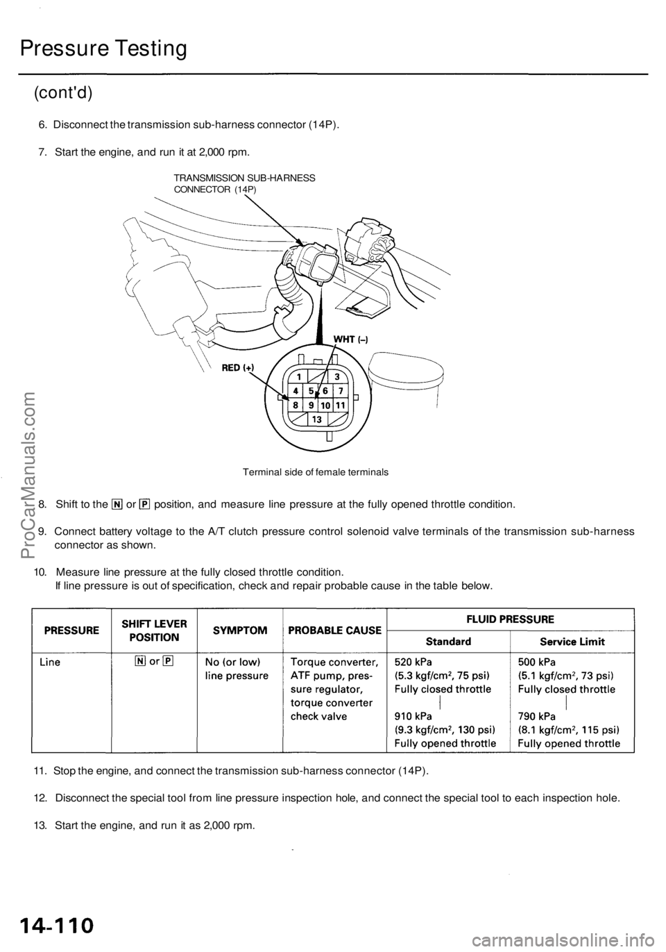
6. Disconnect the transmission sub-harness connector (14P).
7. Start the engine, and run it at 2,000 rpm.
Terminal side of female terminals
8. Shift to the or position, and measure line pressure at the fully opened throttle condition.
9. Connect battery voltage to the A/T clutch pressure control solenoid valve terminals of the transmission sub-harness
connector as shown.
10. Measure line pressure at the fully closed throttle condition.
If line pressure is out of specification, check and repair probable cause in the table below.
11. Stop the engine, and connect the transmission sub-harness connector (14P).
12. Disconnect the special tool from line pressure inspection hole, and connect the special tool to each inspection hole.
13. Start the engine, and run it as 2,000 rpm.
TRANSMISSION SUB-HARNESS
CONNECTOR (14P)ProCarManuals.com
Page 915 of 1954
Maintenance
Differential Oil
NOTE: Check the differential oil with engine OFF, and
the vehicle on level ground.
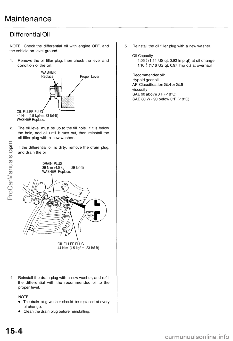
1. Remove the oil filler plug, then check the level and
condition of the oil.
WASHER
Replace.
Proper Lever
OIL FILLER PLUG
44 N-m (4.5 kgf-m, 33 Ibf-ft)
WASHER Replace.
2. The oil level must be up to the fill hole. If it is below
the hole, add oil until it runs out, then reinstall the
oil filler plug with a new washer.
3. If the differential oil is dirty, remove the drain plug,
and drain the oil.
DRAIN PLUG
39 N-m (4.0 kgf-m, 29 Ibf-ft)
WASHER Replace.
OIL FILLER PLUG
44 N-m (4.5 kgf-m, 33 Ibf-ft)
4. Reinstall the drain plug with a new washer, and refill
the differential with the recommended oil to the
proper level.
NOTE:
The drain plug washer should be replaced at every
oil change.
Clean the drain plug before reinstalling.
5. Reinstall the oil filler plug with a new washer.
Oil Capacity
1.05 (1.11 US qt, 0.92 Imp qt) at oil change
1.10 (1.16 US qt, 0.97 Imp qt) at overhaul
Recommended oil:
Hypoid gear oil
API Classification GL4 or GL5
viscosity:
SAE 90 above 0°F (-18°C)
SAE 80 W - 90 below 0°F (-18°C)ProCarManuals.com
Page 981 of 1954
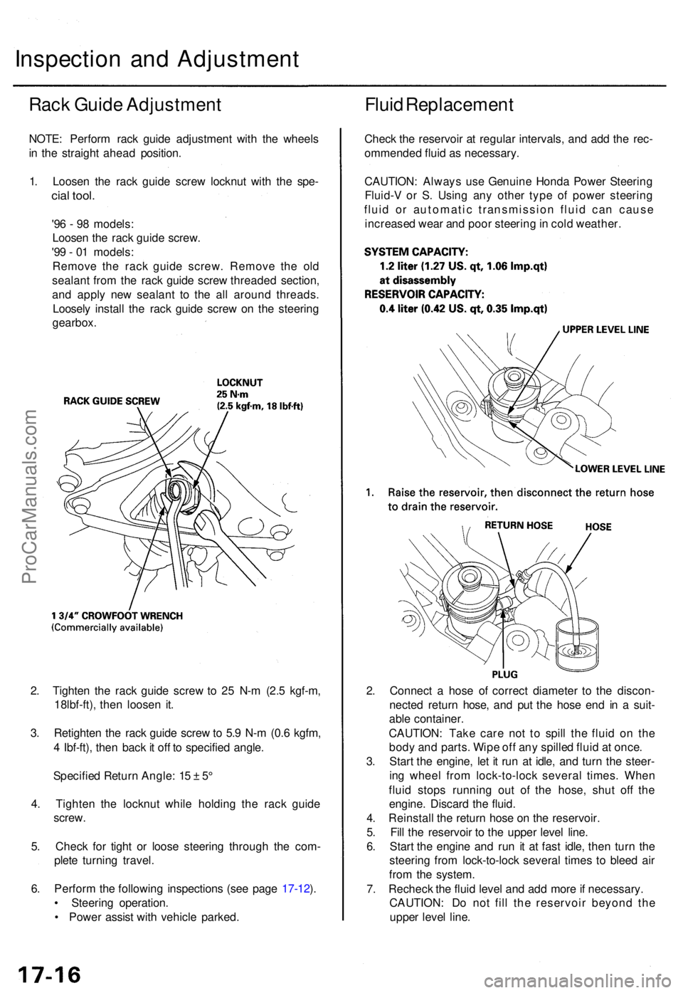
2. Tighte n th e rac k guid e scre w to 2 5 N- m (2. 5 kgf-m ,
18lbf-ft) , the n loose n it .
3 . Retighte n th e rac k guid e scre w to 5. 9 N- m (0. 6 kgfm ,
4 Ibf-ft) , the n bac k it of f t o specifie d angle .
Specifie d Retur n Angle : 1 5 ± 5°
4 . Tighte n th e locknu t whil e holdin g th e rac k guid e
screw .
5 . Chec k fo r tigh t o r loos e steerin g throug h th e com -
plet e turnin g travel .
6 . Perfor m th e followin g inspection s (se e pag e 17-12 ).
• Steerin g operation .
• Powe r assis t wit h vehicl e parked . 2
. Connec t a hos e o f correc t diamete r t o th e discon -
necte d retur n hose , an d pu t th e hos e en d i n a suit -
abl e container .
CAUTION : Tak e car e no t t o spil l th e flui d o n th e
bod y an d parts . Wip e of f an y spille d flui d a t once .
3 . Star t th e engine , le t i t ru n a t idle , an d tur n th e steer -
in g whee l fro m lock-to-loc k severa l times . Whe n
flui d stop s runnin g ou t of the hose , shu t of f th e
engine . Discar d th e fluid .
4 . Reinstal l th e retur n hos e o n th e reservoir .
5 . Fil l th e reservoi r t o th e uppe r leve l line .
6 . Star t th e engin e an d ru n i t a t fas t idle , the n tur n th e
steerin g fro m lock-to-loc k severa l time s t o blee d ai r
fro m th e system .
7 . Rechec k th e flui d leve l an d ad d mor e if necessary .
CAUTION : D o no t fil l th e reservoi r beyon d th e
uppe r leve l line .
Inspectio n an d Adjustmen t
Rack Guid e Adjustmen t
NOTE: Perfor m rac k guid e adjustmen t wit h th e wheel s
i n th e straigh t ahea d position .
1 . Loose n th e rac k guid e scre w locknu t wit h th e spe -
cial tool .
'96 - 9 8 models :
Loose n th e rac k guid e screw .
'9 9 - 0 1 models :
Remov e th e rac k guid e screw . Remov e th e ol d
sealan t fro m th e rac k guid e scre w threade d section ,
an d appl y ne w sealan t t o th e al l aroun d threads .
Loosel y instal l th e rac k guid e scre w o n th e steerin g
gearbox .
Fluid Replacemen t
Check th e reservoi r a t regula r intervals , an d ad d th e rec -
ommende d flui d a s necessary .
CAUTION : Alway s us e Genuin e Hond a Powe r Steerin g
Fluid- V o r S . Usin g an y othe r typ e o f powe r steerin g
flui d o r automati c transmissio n flui d ca n caus e
increase d wea r an d poo r steerin g in col d weather .
ProCarManuals.com
Page 1022 of 1954
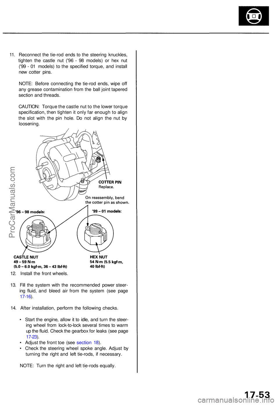
12. Instal l th e fron t wheels .
13 . Fil l th e syste m wit h th e recommende d powe r steer -
in g fluid , an d blee d ai r fro m th e syste m (se e pag e
17-16 ).
14 . Afte r installation , perfor m th e followin g checks .
• Star t th e engine , allo w it t o idle , an d tur n th e steer -
in g whee l fro m lock-to-loc k severa l time s t o war m
u p th e fluid . Chec k th e gearbo x fo r leak s (se e pag e
17-23 ).
• Adjus t th e fron t to e (se e sectio n 18 ).
• Chec k th e steerin g whee l spok e angle . Adjus t b y
turnin g th e righ t an d lef t tie-rods , i f necessary .
NOTE : Tur n th e righ t an d lef t tie-rod s equally .
11
. Reconnec t th e tie-ro d end s t o th e steerin g knuckles ,
tighte n th e castl e nu t ('9 6 - 9 8 models ) o r he x nu t
('9 9 - 0 1 models ) t o th e specifie d torque , an d instal l
ne w cotte r pins .
NOTE : Befor e connectin g th e tie-ro d ends , wip e of f
an y greas e contaminatio n fro m th e bal l join t tapere d
sectio n an d threads .
CAUTION : Torqu e th e castl e nu t t o th e lowe r torqu e
specification , the n tighte n it onl y fa r enoug h to alig n
th e slo t wit h th e pi n hole . D o no t alig n th e nu t b y
loosening .
ProCarManuals.com