bolt pattern ACURA TL 1995 Service User Guide
[x] Cancel search | Manufacturer: ACURA, Model Year: 1995, Model line: TL, Model: ACURA TL 1995Pages: 1771, PDF Size: 62.49 MB
Page 1083 of 1771
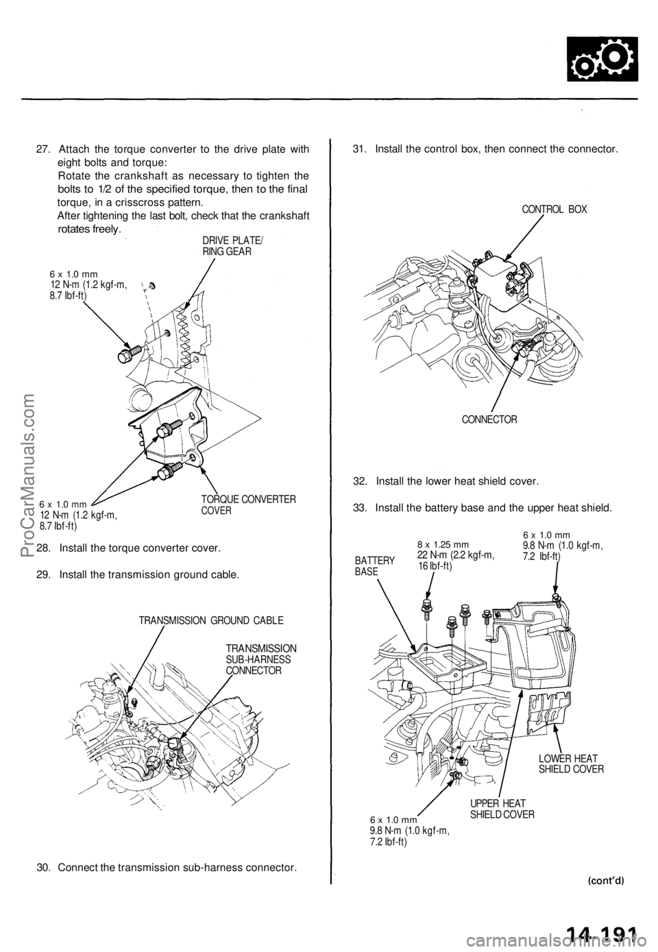
27. Attach the torque converter to the drive plate with
eight bolts and torque:
Rotate the crankshaft as necessary to tighten the
bolts to 1/2 of the specified torque, then to the final
torque, in a crisscross pattern.
After tightening the last bolt, check that the crankshaft
rotates freely.
DRIVE PLATE/
RING GEAR
6 x 1.0 mm
12 N-m (1.2 kgf-m,
8.7 Ibf-ft)
6 x 1.0 mm
12 N-m (1.2 kgf-m,
8.7 Ibf-ft)
TORQUE CONVERTER
COVER
28. Install the torque converter cover.
29. Install the transmission ground cable.
TRANSMISSION GROUND CABLE
TRANSMISSION
SUB-HARNESS
CONNECTOR
30. Connect the transmission sub-harness connector.
31. Install the control box, then connect the connector.
CONTROL BOX
CONNECTOR
32. Install the lower heat shield cover.
33. Install the battery base and the upper heat shield.
6 x 1.0 mm
9.8 N-m (1.0 kgf-m,
7.2 Ibf-ft)
LOWER HEAT
SHIELD COVER
6 x 1.0 mm
9.8 N-m (1.0 kgf-m,
7.2 Ibf-ft)
UPPER HEAT
SHIELD COVER
8 x
1.25
mm
22 N-m (2.2 kgf-m,
16 Ibf-ft)
BATTERY
BASEProCarManuals.com
Page 1101 of 1771
Differential Assembl y
Inspection (cont'd )
Bearing preloa d
6 . Remov e th e differentia l cas e cove r an d th e differen -
tia l carrier .
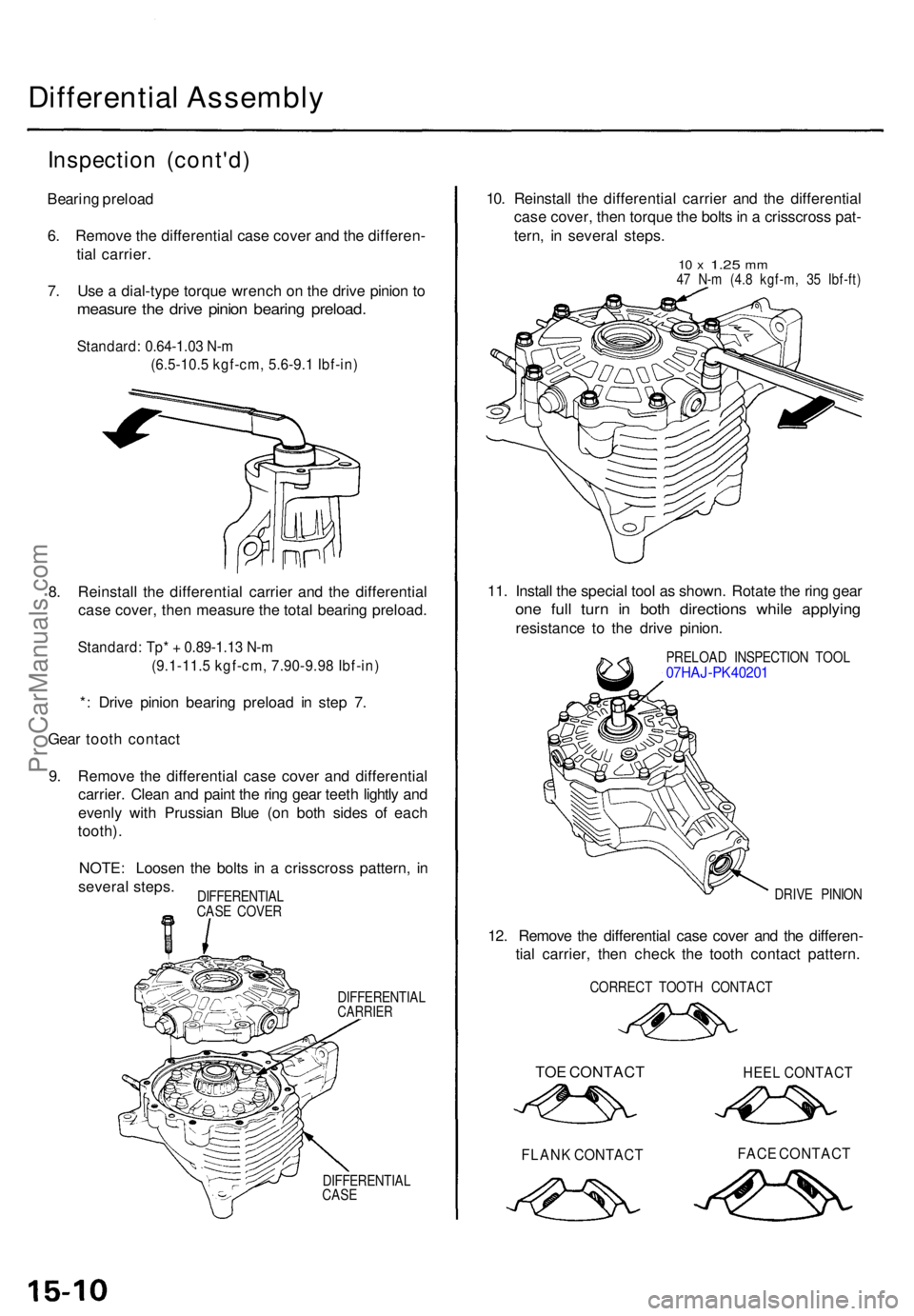
7 . Us e a dial-typ e torqu e wrenc h o n th e driv e pinio n t o
measur e th e driv e pinio n bearin g preload .
Standard: 0.64-1.03 N-m
(6.5-10.5 kgf-cm, 5.6-9.1 Ibf-in)
8. Reinstal l th e differentia l carrie r an d th e differentia l
cas e cover , the n measur e th e tota l bearin g preload .
Standard: Tp* + 0.89-1.13 N-m
(9.1-11.5 kgf-cm, 7.90-9.98 Ibf-in)
*: Driv e pinio n bearin g preloa d i n ste p 7 .
Gea r toot h contac t
9 . Remov e th e differentia l cas e cove r an d differentia l
carrier . Clea n an d pain t th e rin g gea r teet h lightl y an d
evenl y with Prussia n Blu e (o n bot h side s o f eac h
tooth) .
NOTE : Loose n th e bolt s i n a crisscros s pattern , i n
severa l steps .
DIFFERENTIA LCARRIER
DIFFERENTIA L
CAS E
10. Reinstal l th e differentia l carrie r an d th e differentia l
cas e cover , the n torqu e th e bolt s in a crisscros s pat -
tern , i n severa l steps .
10 x 1.2 5 mm47 N- m (4. 8 kgf-m , 3 5 Ibf-ft )
11. Instal l th e specia l too l a s shown . Rotat e th e rin g gea r
one ful l tur n i n bot h direction s whil e applyin g
resistanc e t o th e driv e pinion .
PRELOA D INSPECTIO N TOO L07HAJ-PK40201
DRIVE PINIO N
12. Remov e th e differentia l cas e cove r an d th e differen -
tia l carrier , the n chec k th e toot h contac t pattern .
CORREC T TOOT H CONTAC T
TOE CONTAC T HEE L CONTAC T
FLANK CONTAC T FAC E CONTAC T
DIFFERENTIA L
CAS E COVE R
ProCarManuals.com
Page 1102 of 1771
Disassembly
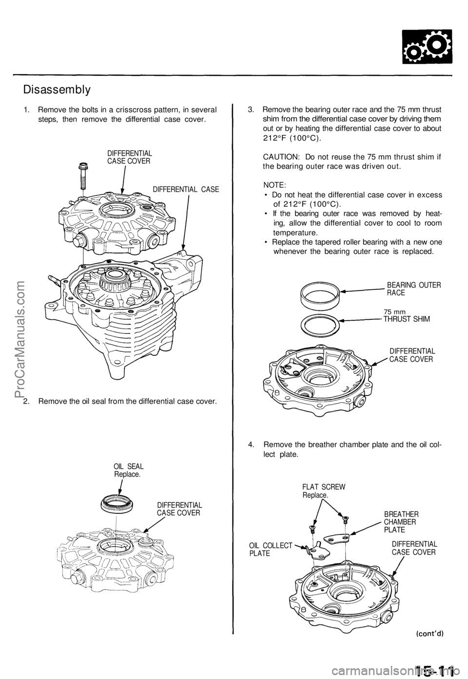
1. Remov e th e bolt s in a crisscros s pattern , i n severa l
steps , the n remov e th e differentia l cas e cover .
DIFFERENTIA L
CAS E COVE R
DIFFERENTIA L CAS E
2. Remov e th e oi l sea l fro m th e differentia l cas e cover .
OIL SEA LReplace .
DIFFERENTIA L
CAS E COVE R
3. Remov e th e bearin g oute r rac e an d th e 7 5 m m thrus t
shim fro m th e differentia l cas e cove r b y drivin g the m
out o r b y heatin g th e differentia l cas e cove r t o abou t
212°F (100°C) .
CAUTION : D o no t reus e th e 7 5 m m thrus t shi m if
th e bearin g oute r rac e wa s drive n out .
NOTE :
• D o no t hea t th e differentia l cas e cove r i n exces s
of 212° F (100°C) .
• I f th e bearin g oute r rac e wa s remove d b y heat -
ing , allo w th e differentia l cove r t o coo l t o roo m
temperature .
• Replac e th e tapere d rolle r bearin g wit h a ne w on e
wheneve r th e bearin g oute r rac e i s replaced .
BEARING OUTE RRACE
75 m mTHRUS T SHI M
DIFFERENTIA L
CAS E COVE R
4. Remov e th e breathe r chambe r plat e an d th e oi l col -
lec t plate .
FLAT SCRE W
Replace .
BREATHER
CHAMBE R
PLATE
OIL COLLEC T
PLAT E DIFFERENTIA
L
CAS E COVE R
ProCarManuals.com
Page 1107 of 1771
Backlash Inspectio n
1. Remov e th e tapere d rolle r bearing s (se e pag e 15-14 ).
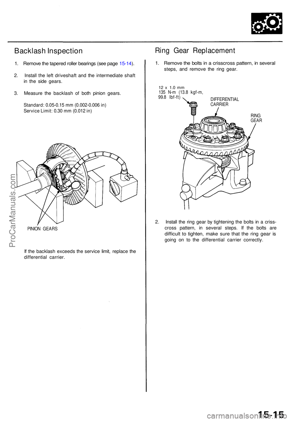
2 . Instal l th e lef t driveshaf t an d th e intermediat e shaf t
i n th e sid e gears .
3 . Measur e th e backlas h o f bot h pinio n gears .
Standard: 0.05-0.15 mm (0.002-0.006 in)
Service Limit: 0.30 mm (0.012 in)
PINION GEAR S
If th e backlas h exceed s th e servic e limit , replac e th e
differentia l carrier .
Ring Gea r Replacemen t
1. Remov e th e bolt s in a crisscros s pattern , i n severa l
steps, an d remov e th e rin g gear .
12 x 1. 0 m m135 N- m (13. 8 kgf-m ,
99. 8 Ibf-ft )
DIFFERENTIAL
CARRIER
RINGGEA R
2. Instal l th e rin g gea r b y tightenin g th e bolt s i n a criss -
cros s pattern , i n severa l steps . I f th e bolt s ar e
difficul t t o tighten , mak e sur e tha t th e rin g gea r i s
goin g o n t o th e differentia l carrie r correctly .
ProCarManuals.com
Page 1111 of 1771
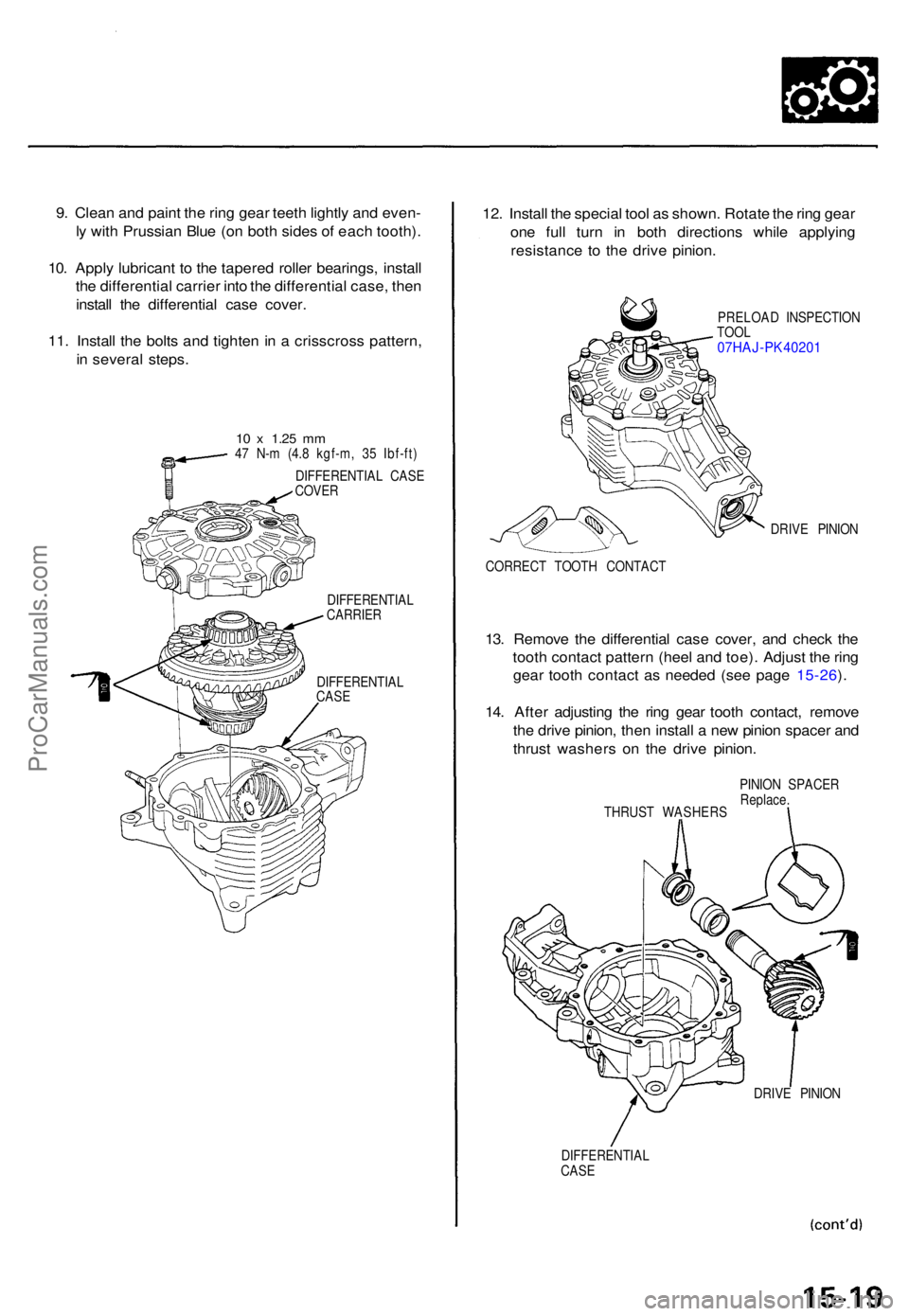
9. Clea n an d pain t th e rin g gea r teet h lightl y an d even -
l y wit h Prussia n Blu e (o n bot h side s o f eac h tooth) .
10 . Appl y lubrican t t o th e tapere d rolle r bearings , instal l
th e differentia l carrie r int o th e differentia l case , the n
instal l th e differentia l cas e cover .
11 . Instal l th e bolt s an d tighte n in a crisscros s pattern ,
i n severa l steps .
10 x 1.2 5 mm47 N- m (4. 8 kgf-m , 3 5 Ibf-ft )
DIFFERENTIA L CAS E
COVE R
DIFFERENTIA L
CARRIER
DIFFERENTIA L
CAS E
12. Instal l th e specia l too l a s shown . Rotat e th e rin g gea r
on e ful l tur n i n bot h direction s whil e applyin g
resistanc e t o th e driv e pinion .
PRELOA D INSPECTIO N
TOO L
07HAJ-PK40201
DRIV E PINIO N
CORREC T TOOT H CONTAC T
13. Remov e th e differentia l cas e cover , an d chec k th e
toot h contac t patter n (hee l an d toe) . Adjus t th e rin g
gea r toot h contac t a s neede d (se e pag e 15-26 ).
14 . Afte r adjustin g th e rin g gea r toot h contact , remov e
th e driv e pinion , the n instal l a ne w pinio n space r an d
thrus t washer s o n th e driv e pinion .
THRUS T WASHER SPINIO
N SPACE R
Replace .
DRIV E PINIO N
DIFFERENTIA L
CAS E
ProCarManuals.com
Page 1115 of 1771
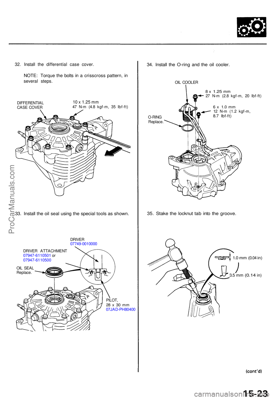
32. Instal l th e differentia l cas e cover .
NOTE: Torqu e th e bolt s i n a crisscros s pattern , i n
severa l steps .
DIFFERENTIA L
CAS E COVE R10 x 1.2 5 m m47 N- m (4. 8 kgf-m , 3 5 Ibf-ft )
33. Instal l th e oi l sea l usin g th e specia l tool s a s shown .
DRIVER07749-001000 0
DRIVER ATTACHMEN T07947-6110501 o r
07947-611050 0
OIL SEA L
Replace .
PILOT,
28 x 30 m m07JAD-PH80400
34. Instal l th e O-rin g an d th e oi l cooler .
OIL COOLE R
O-RIN G
Replace .
8 x 1.2 5 mm27 N- m (2. 8 kgf-m , 2 0 Ibf-ft )
6 x 1. 0 m m12 N- m (1. 2 kgf-m ,8.7 Ibf-ft )
35. Stak e th e locknu t ta b int o th e groove .
1.0 m m (0.04 in)
3.5 m m (0.1 4 in)
ProCarManuals.com