oil reset ACURA TL 1995 Service Repair Manual
[x] Cancel search | Manufacturer: ACURA, Model Year: 1995, Model line: TL, Model: ACURA TL 1995Pages: 1771, PDF Size: 62.49 MB
Page 96 of 1771
Cylinder Heads
Installation
Install th e cylinde r head s in th e revers e orde r o f removal .
NOTE:
Alway s us e ne w cylinde r hea d gaskets .
Cylinde r head s an d cylinde r bloc k surfac e mus t b e
clean .
Turn th e camshaft s s o th e pulle y locatin g pi n hole s
are a t th e top .
Turn th e crankshaf t s o th e No . 1 pisto n is a t TD C (se e
pag e 6-8 ).
Clea n th e oi l contro l orifice s befor e installing .
D o no t us e th e uppe r an d lowe r cover s t o stor e
remove d item .
Clea n th e uppe r an d lowe r cover s befor e installation .
1 . Alig n th e cylinde r hea d dowe l pins .
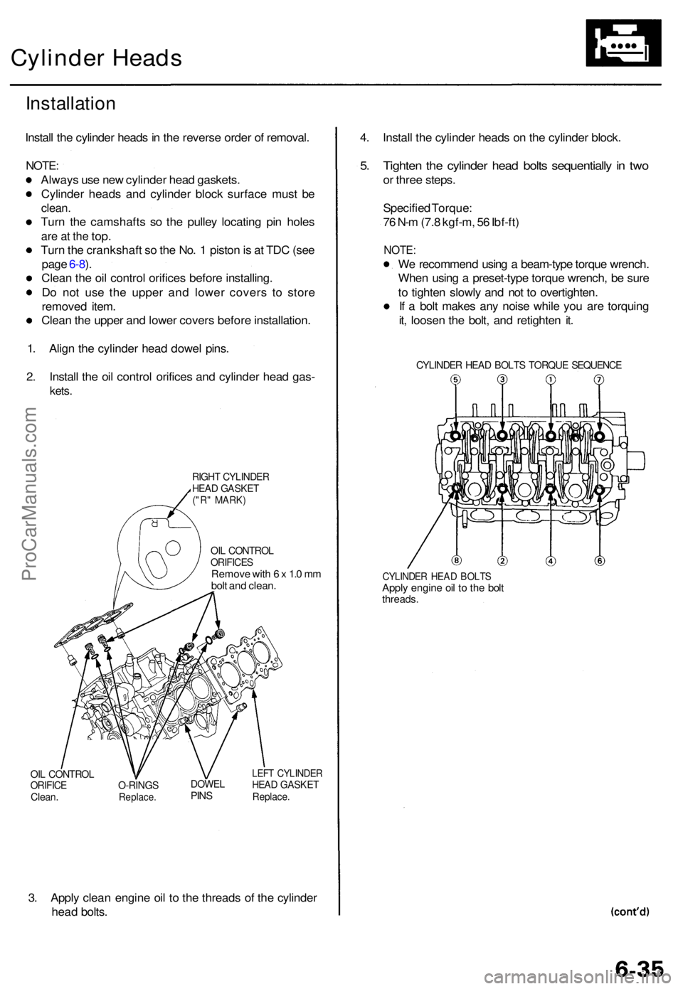
2 . Instal l th e oi l contro l orifice s an d cylinde r hea d gas -
kets.
RIGH T CYLINDE RHEAD GASKE T("R" MARK )
OIL CONTRO LORIFICESRemove wit h 6 x 1. 0 m m
bol t an d clean .
OIL CONTRO LORIFICEClean.O-RING SReplace .
DOWELPINS
LEF T CYLINDE RHEAD GASKE TReplace.
3. Appl y clea n engin e oi l t o th e thread s o f th e cylinde r
hea d bolts . 4
. Instal l th e cylinde r head s o n th e cylinde r block .
5. Tighte n th e cylinde r hea d bolt s sequentiall y in tw o
or thre e steps .
Specifie d Torque :
7 6 N- m (7. 8 kgf-m , 5 6 Ibf-ft )
NOTE :
We recommen d usin g a beam-typ e torqu e wrench .
Whe n usin g a preset-typ e torqu e wrench , b e sur e
t o tighte n slowl y an d no t t o overtighten .
I f a bol t make s an y nois e whil e yo u ar e torquin g
it , loose n th e bolt , an d retighte n it .
CYLINDE R HEA D BOLT S TORQU E SEQUENC E
CYLINDER HEA D BOLT SApply engin e oi l t o th e bol tthreads .
ProCarManuals.com
Page 565 of 1771
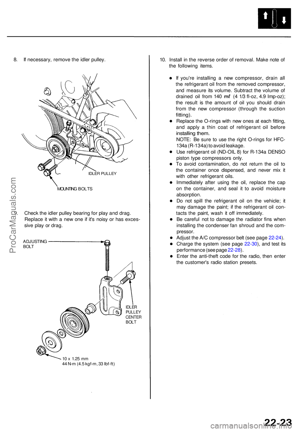
8. I f necessary , remov e th e idle r pulley .
IDLER PULLE Y
9.
MOUNTIN G BOLT S
Check th e idle r pulle y bearin g fo r pla y an d drag .
Replac e it wit h a ne w on e i f it' s nois y o r ha s exces -
siv e pla y o r drag .
ADJUSTIN GBOLT
IDLE RPULLE YCENTE RBOLT
10 x 1.2 5 mm44 N- m (4. 5 kgf-m , 3 3 Ibf-ft )
10. Instal l i n th e revers e orde r o f removal . Mak e not e o f
th e followin g items .
I f you'r e installin g a ne w compressor , drai n al l
th e refrigeran t oi l fro m th e remove d compressor ,
an d measur e it s volume . Subtrac t th e volum e o f
draine d oi l fro m 14 0 ( 4 1/ 3 fl-oz , 4. 9 Imp-oz) ;
th e resul t i s th e amoun t o f oi l yo u shoul d drai n
fro m th e ne w compresso r (throug h th e suctio n
fitting).
Replac e th e O-rings with ne w one s a t eac h fitting ,
an d appl y a thi n coa t of refrigeran t oi l befor e
installin g them .
NOTE : B e sur e t o us e th e righ t O-ring s fo r HFC -
134 a (R-134a ) t o avoi d leakage .
Us e refrigeran t oi l (ND-OI L 8 ) fo r R-134 a DENS O
pisto n typ e compressor s only .
T o avoi d contamination , d o no t retur n th e oi l t o
th e containe r onc e dispensed , an d neve r mi x i t
wit h othe r refrigeran t oils .
Immediatel y afte r usin g th e oil , replac e th e ca p
o n th e container , an d sea l i t t o avoi d moistur e
absorption .
D o no t spil l th e refrigeran t oi l o n th e vehicle ; i t
ma y damag e th e paint ; i f th e refrigeran t oi l con -
tact s th e paint , was h i t of f immediately .
B e carefu l no t t o damag e th e radiato r fin s whe n
installin g th e condense r fa n shrou d an d th e com -
pressor .
Adjust th e A/ C compresso r bel t (se e pag e 22-24 ).
Charg e th e syste m (se e pag e 22-30 ), an d tes t it s
performanc e (se e pag e 22-28 ).
Ente r th e anti-thef t cod e fo r th e radio , the n ente r
th e customer' s radi o statio n presets .
ProCarManuals.com
Page 586 of 1771
Starter Solenoid Test
1. Make sure you have the anti-theft code for the
radio, then write down the frequencies for the
radio's preset buttons.
2. Disconnect the battery negative cable, then discon-
nect the positive cable.
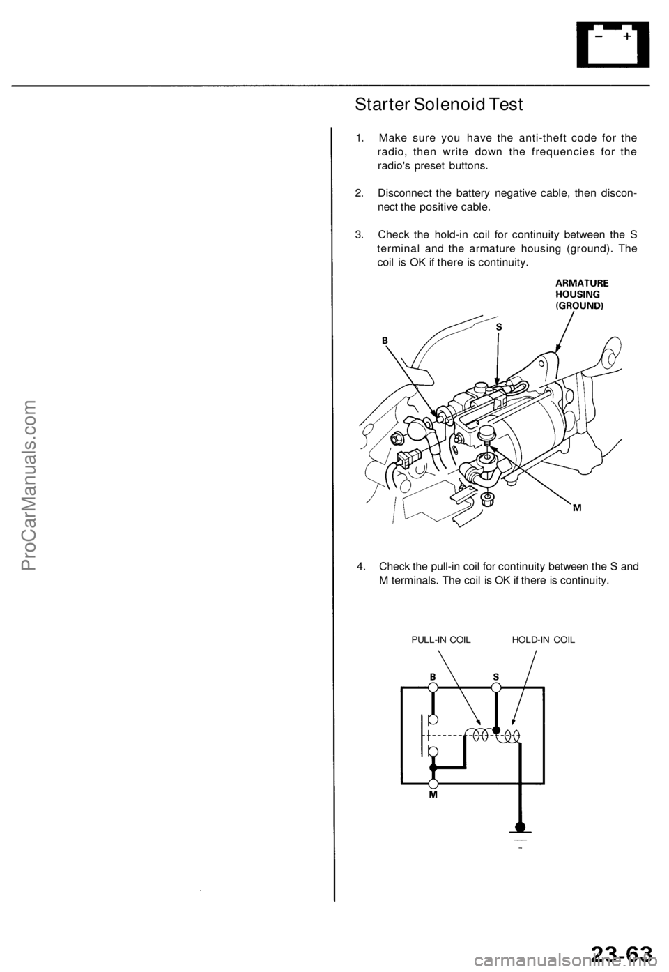
3. Check the hold-in coil for continuity between the S
terminal and the armature housing (ground). The
coil is OK if there is continuity.
4. Check the pull-in coil for continuity between the S and
M terminals. The coil is OK if there is continuity.
PULL-IN COIL HOLD-IN COILProCarManuals.com
Page 775 of 1771
Cylinder Head
Installation (cont'd)
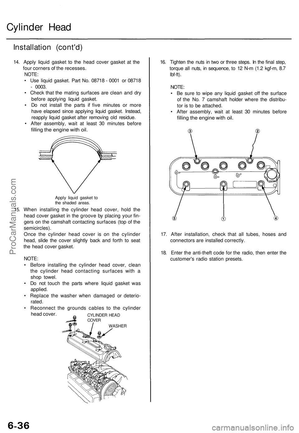
14. Apply liquid gasket to the head cover gasket at the
four corners of the recesses.
NOTE:
• Use liquid gasket. Part No. 08718 - 0001 or 08718
- 0003.
• Check that the mating surfaces are clean and dry
before applying liquid gasket.
• Do not install the parts if five minutes or more
have elapsed since applying liquid gasket. Instead,
reapply liquid gasket after removing old residue.
• After assembly, wait at least 30 minutes before
filling the engine with oil.
15.
Apply liquid gasket to
the shaded areas.
When installing the cylinder head cover, hold the
head cover gasket in the groove by placing your fin-
gers on the camshaft contacting surfaces (top of the
semicircles).
Once the cylinder head cover is on the cylinder
head, slide the cover slightly back and forth to seat
the head cover gasket.
NOTE:
• Before installing the cylinder head cover, clean
the cylinder head contacting surfaces with a
shop towel.
• Do not touch the parts where liquid gasket was
applied.
• Replace the washer when damaged or deterio-
rated.
• Reconnect the grounds cables to the cylinder
head cover.
16. Tighten the nuts in two or three steps. In the final step,
torque all nuts, in sequence, to 12 N-m (1.2 kgf-m, 8.7
Ibf-ft).
NOTE:
• Be sure to wipe any liquid gasket off the surface
of the No. 7 camshaft holder where the distribu-
tor is to be attached.
• After assembly, wait at least 30 minutes before
filling the engine with oil.
17. After installation, check that all tubes, hoses and
connectors are installed correctly.
18. Enter the anti-theft code for the radio, then enter the
customer's radio station presets.
CYLINDER HEAD
COVER
WASHERProCarManuals.com
Page 1558 of 1771
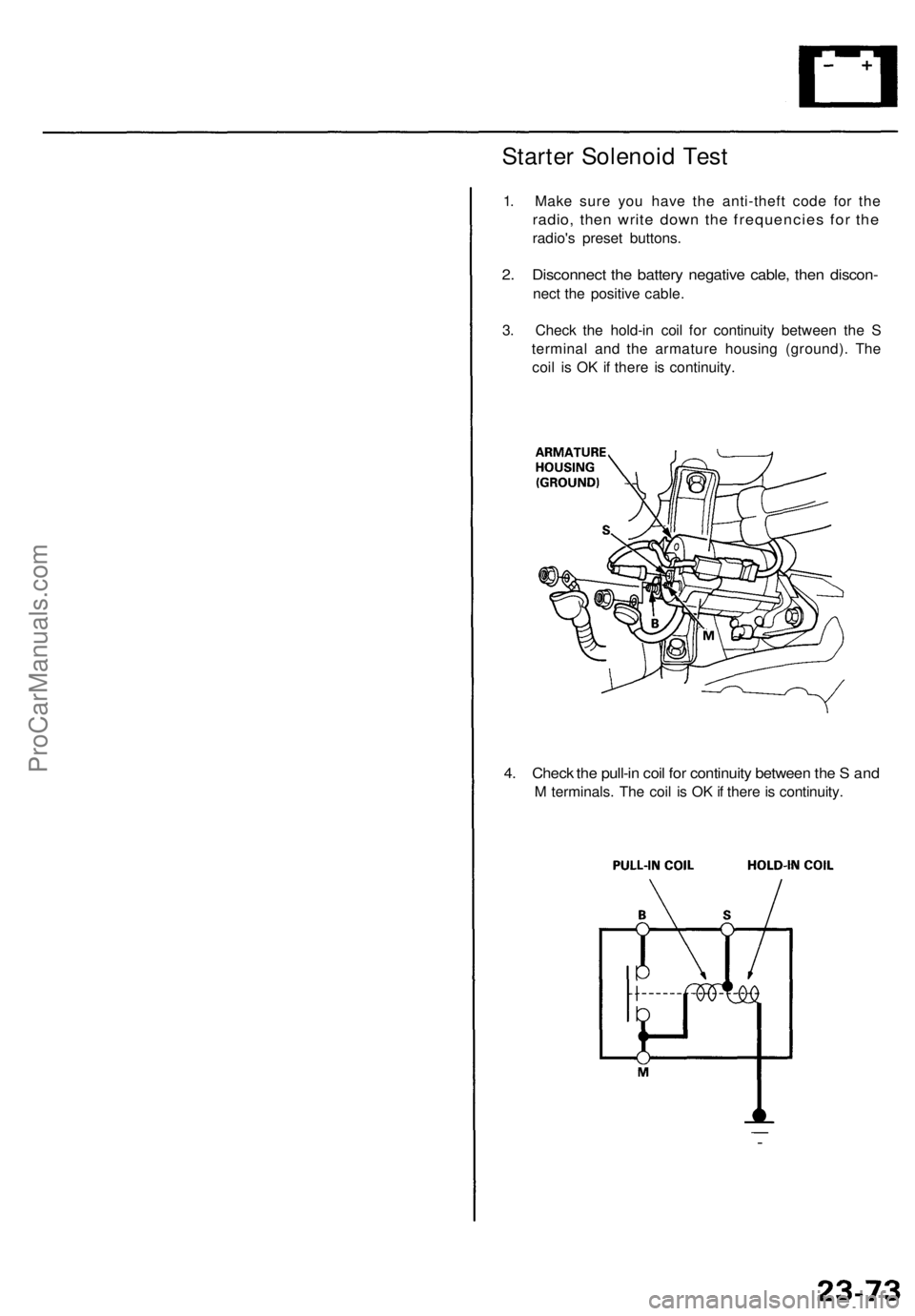
Starter Solenoid Test
1. Make sure you have the anti-theft code for the
radio, then write down the frequencies for the
radio's preset buttons.
2. Disconnect the battery negative cable, then discon-
nect the positive cable.
3. Check the hold-in coil for continuity between the S
terminal and the armature housing (ground). The
coil is OK if there is continuity.
4. Check the pull-in coil for continuity between the S and
M terminals. The coil is OK if there is continuity.ProCarManuals.com