differential ACURA TL 1995 Service Owner's Guide
[x] Cancel search | Manufacturer: ACURA, Model Year: 1995, Model line: TL, Model: ACURA TL 1995Pages: 1771, PDF Size: 62.49 MB
Page 1108 of 1771
Differential Assembl y
Reassembl y
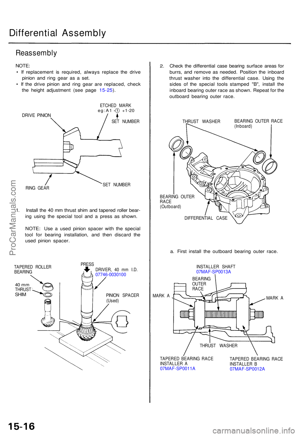
NOTE:
• I f replacemen t i s required , alway s replac e th e driv e
pinio n an d rin g gea r a s a set .
• I f th e driv e pinio n an d rin g gea r ar e replaced , chec k
th e heigh t adjustmen t (se e pag e 15-25 ).
DRIV E PINIO N
ETCHE D MAR Keg:A1 +1-2 0
SET NUMBE R
RIN G GEA R SE
T NUMBE R
1. Instal l th e 4 0 m m thrus t shi m an d tapere d rolle r bear -
in g usin g th e specia l too l an d a pres s a s shown .
NOTE : Us e a use d pinio n space r wit h th e specia l
too l fo r bearin g installation , an d the n discar d th e
use d pinio n spacer .
TAPERE D ROLLE R
BEARIN G
40 m mTHRUS TSHIM
PRES S
DRIVER , 4 0 m m I.D .
07746-0030100
PINIO N SPACE R
(Used )
2.Chec k th e differentia l cas e bearin g surfac e area s fo r
burrs , an d remov e a s needed . Positio n th e inboar d
thrus t washe r int o th e differentia l case . Usin g th e
side s o f th e specia l tool s stampe d "B" , instal l th e
inboar d bearin g oute r rac e a s shown . Repea t fo r th e
outboar d bearin g oute r race .
THRUS T WASHER BEARIN
G OUTE R RAC E
(Inboard )
BEARIN G OUTE R
RAC E
(Outboard )
DIFFERENTIA L CAS E
a. Firs t instal l th e outboar d bearin g oute r race .
INSTALLE R SHAF T07MAF-SP0013A
MARK A
MARK A
TAPERE D BEARIN G RAC E
INSTALLE R A
07MAF-SP0011A
TAPERE D BEARIN G RAC E
INSTALLE R B
07MAF-SP0012A
THRUS T WASHE R
BEARIN
G
OUTE R
RACE
ProCarManuals.com
Page 1110 of 1771
Differential Assembl y
Reassembl y (cont'd )
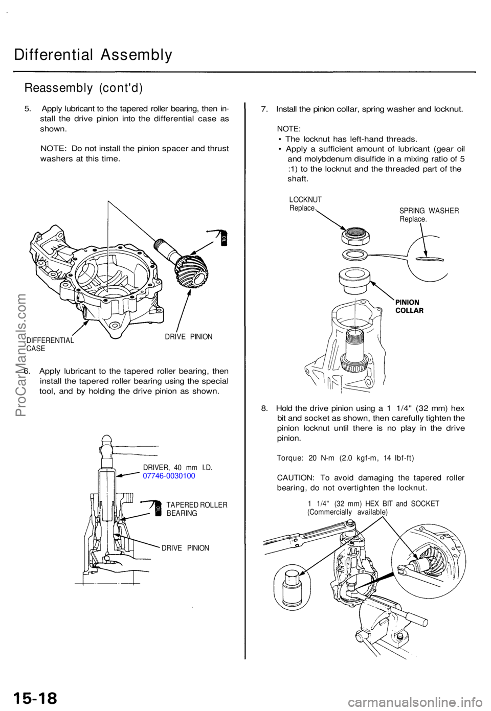
5. Appl y lubrican t t o th e tapere d rolle r bearing , the n in -
stal l th e driv e pinio n int o th e differentia l cas e a s
shown .
NOTE : D o no t instal l th e pinio n space r an d thrus t
washer s a t thi s time .
DIFFERENTIA L
CAS E DRIV
E PINIO N
6. Appl y lubrican t t o th e tapere d rolle r bearing , the n
instal l th e tapere d rolle r bearin g usin g th e specia l
tool , an d b y holdin g th e driv e pinio n a s shown .
DRIVER , 4 0 m m I.D .07746-0030100
TAPERE D ROLLE R
BEARIN G
DRIV E PINIO N
7. Instal l th e pinio n collar , sprin g washe r an d locknut .
NOTE:
• Th e locknu t ha s left-han d threads .
• Appl y a sufficien t amoun t o f lubrican t (gea r oi l
an d molybdenu m disulfid e in a mixin g rati o o f 5
: 1 ) t o th e locknu t an d th e threade d par t o f th e
shaft .
LOCKNU T
Replac e
SPRING WASHE R
Replace .
8. Hol d th e driv e pinio n usin g a 1 1/4 " (3 2 mm ) he x
bi t an d socke t a s shown , the n carefull y tighte n th e
pinio n locknu t unti l ther e i s n o pla y i n th e driv e
pinion .
Torque : 2 0 N- m (2. 0 kgf-m , 1 4 Ibf-ft )
CAUTION : T o avoi d damagin g th e tapere d rolle r
bearing , d o no t overtighte n th e locknut .
1 1/4 " (3 2 mm ) HE X BI T an d SOCKE T
(Commerciall y available )
ProCarManuals.com
Page 1112 of 1771
Differential Assembl y
Reassembl y (cont'd )
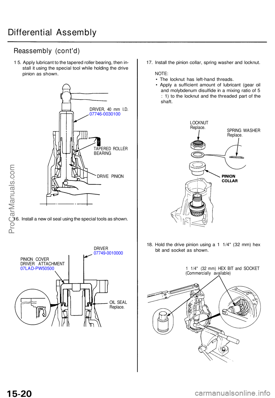
1 5 . Appl y lubrican t t o th e tapere d rolle r bearing , the n in -
stal l i t usin g th e specia l too l whil e holdin g th e driv e
pinio n a s shown .
DRIVER , 4 0 m m I.D .07746-0030100
TAPERE D ROLLE RBEARING
DRIVE PINIO N
16. Instal l a ne w oi l sea l usin g th e specia l tool s a s shown .
PINION COVE R
DRIVE R ATTACHMEN T
07LAD-PW50500
DRIVER07749-0010000
OIL SEA L
Replace .
17. Instal l th e pinio n collar , sprin g washe r an d locknut .
NOTE:
• Th e locknu t ha s left-han d threads .
• Appl y a sufficien t amoun t o f lubrican t (gea r oi l
an d molybdenu m disulfid e in a mixin g rati o o f 5
: 1 ) t o th e locknu t an d th e threade d par t o f th e
shaft .
LOCKNU T
Replace .
SPRING WASHE R
Replace .
18. Hol d th e driv e pinio n usin g a 1 1/4 " (3 2 mm ) he x
bi t an d socke t a s shown.
1 1/4 " (3 2 mm ) HE X BI T an d SOCKE T
(Commerciall y available )
ProCarManuals.com
Page 1114 of 1771
Differential Assembl y
Reassembl y (cont'd )
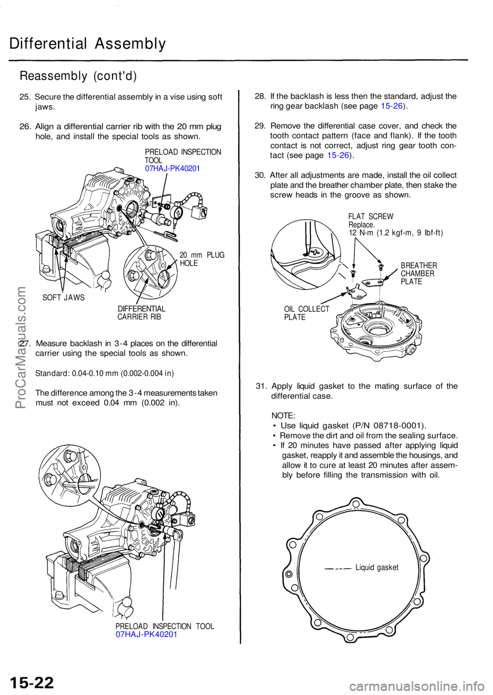
25. Secur e th e differentia l assembl y in a vis e usin g sof t
jaws .
26. Alig n a differentia l carrie r ri b wit h th e 2 0 m m plu g
hole , an d instal l th e specia l tool s a s shown .
PRELOA D INSPECTIO NTOOL07HAJ-PK40201
20 m m PLU G
HOL E
SOF T JAW S
DIFFERENTIA LCARRIER RI B
27. Measur e backlas h in 3- 4 place s o n th e differentia l
carrie r usin g th e specia l tool s a s shown .
Standard: 0.04-0.10 mm (0.002-0.004 in)
The differenc e amon g th e 3- 4 measurement s take n
mus t no t excee d 0.0 4 m m (0.00 2 in) .
PRELOA D INSPECTIO N TOO L07HAJ-PK4020 1
28. I f th e backlas h is les s the n th e standard , adjus t th e
rin g gea r backlas h (se e pag e 15-26 ).
29 . Remov e th e differentia l cas e cover , an d chec k th e
toot h contac t patter n (fac e an d flank) . I f th e toot h
contac t i s no t correct , adjus t rin g gea r toot h con -
tac t (se e pag e 15-26 ).
30 . Afte r al l adjustment s ar e made , instal l th e oi l collec t
plat e an d th e breathe r chambe r plate , the n stak e th e
scre w head s i n th e groov e a s shown .
FLAT SCRE W
Replace .
12 N- m (1. 2 kgf-m , 9 Ibf-ft )
BREATHE RCHAMBER
PLAT E
OI L COLLEC T
PLAT E
31. Appl y liqui d gaske t t o th e matin g surfac e of the
differentia l case .
NOTE :
• Us e liqui d gaske t (P/ N 08718-0001) .
• Remov e th e dir t an d oi l fro m th e sealin g surface .
• I f 2 0 minute s hav e passe d afte r applyin g liqui d
gasket , reappl y it an d assembl e th e housings , an d
allo w it t o cur e a t leas t 2 0 minute s afte r assem -
bl y befor e fillin g th e transmissio n wit h oil .
Liqui d gaske t
ProCarManuals.com
Page 1116 of 1771
Differential Assembl y
Reassembl y (cont'd )
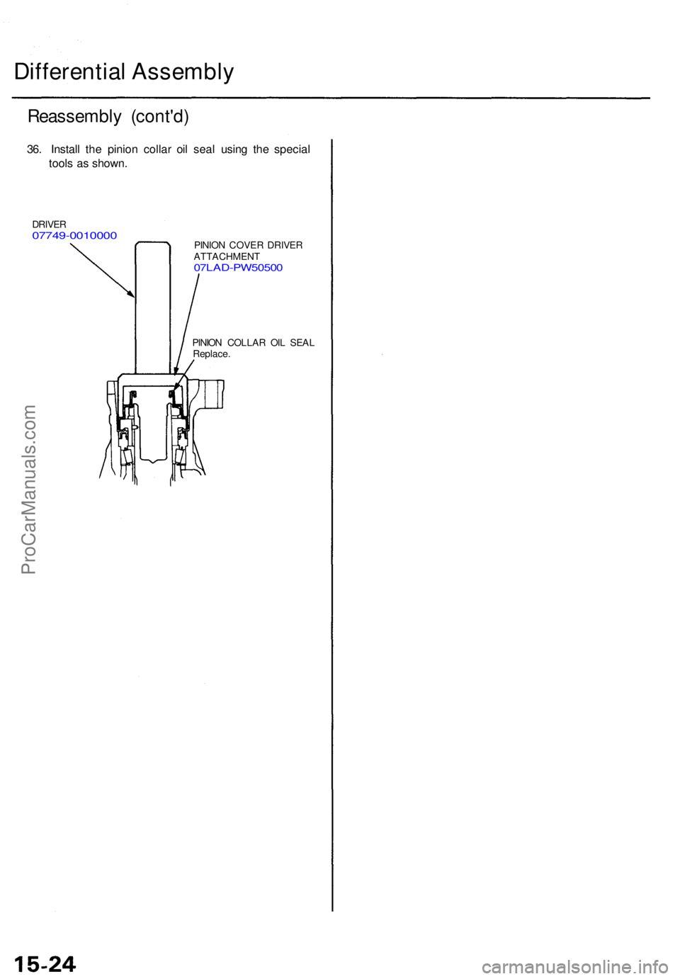
36. Instal l th e pinio n colla r oi l sea l usin g th e specia l
tool s a s shown .
DRIVER07749-001000 0PINION COVE R DRIVE R
ATTACHMEN T
07LAD-PW5050 0
PINION COLLA R OI L SEA L
Replace .
ProCarManuals.com
Page 1119 of 1771
Differential Assembl y
Installation
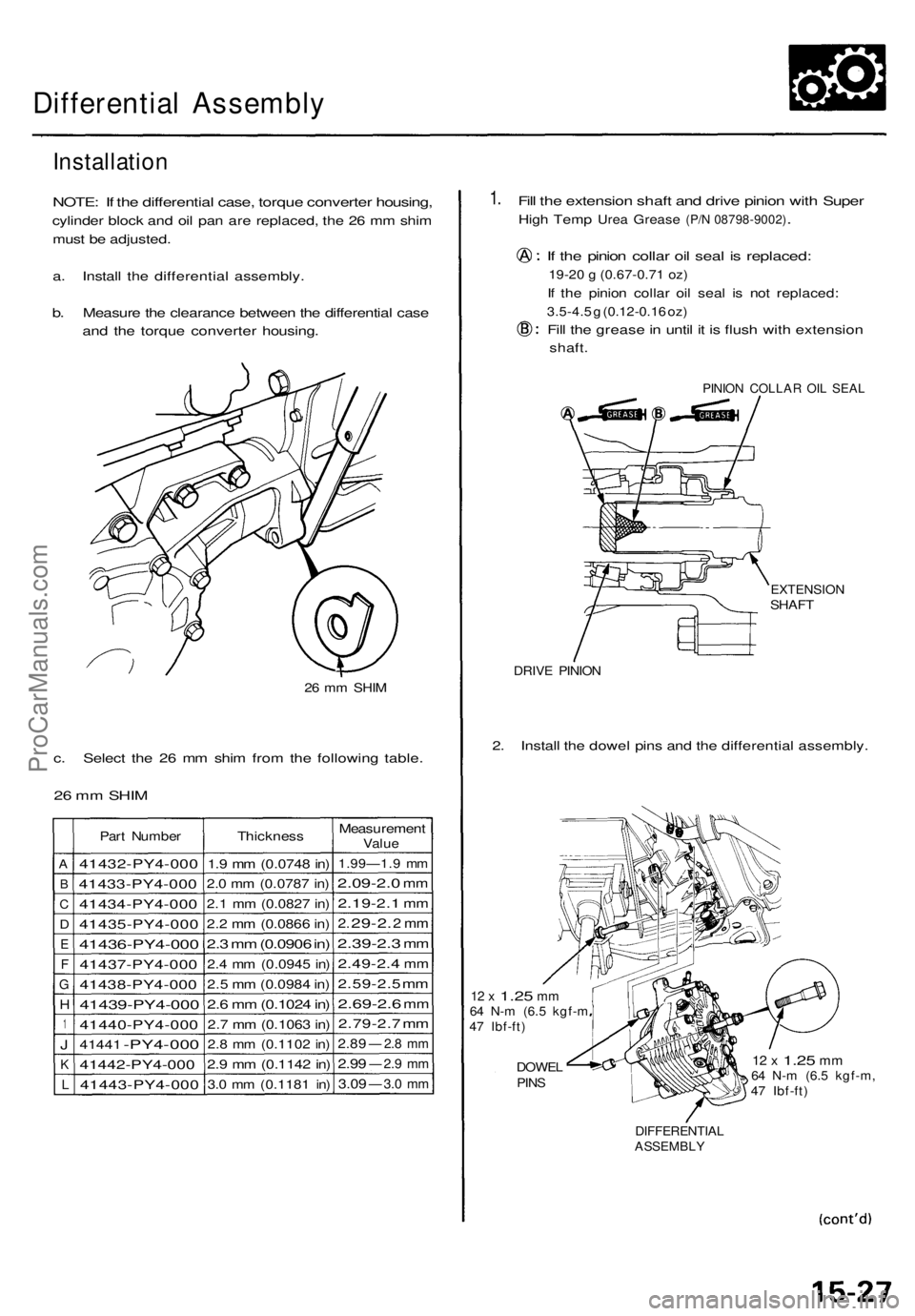
NOTE: I f th e differentia l case , torqu e converte r housing ,
cylinder bloc k an d oi l pa n ar e replaced , th e 2 6 m m shi m
mus t b e adjusted .
a. Instal l th e differentia l assembly .
b. Measur e th e clearanc e betwee n th e differentia l cas e
and th e torqu e converte r housing .
26 m m SHI M
c. Selec t th e 2 6 m m shi m fro m th e followin g table .
26 m m SHI M
A
B
C
D
E
F
G
H
1
J
K
L
Part Numbe r
41432-PY4-00 0
41433-PY4-00 0
41434-PY4-00 0
41435-PY4-00 0
41436-PY4-000
41437-PY4-00 0
41438-PY4-00 0
41439-PY4-000
41440-PY4-00 0
41441 -PY4-00 0
41442-PY4-00 0
41443-PY4-00 0
Thickness
1.9 m m (0.074 8 in )
2.0 m m (0.078 7 in )
2.1 m m (0.082 7 in )
2.2 m m (0.086 6 in )
2.3 m m (0.090 6 in )
2. 4 m m (0.094 5 in )
2.5 m m (0.098 4 in )
2.6 m m (0.102 4 in )
2.7 m m (0.106 3 in )
2.8 m m (0.110 2 in )
2.9 m m (0.114 2 in )
3.0 m m (0.118 1 in )
Measuremen tValue
1.99—1. 9 m m
2.09-2. 0 mm
2.19-2. 1 mm
2. 29-2 . 2 m m
2.39-2. 3 mm
2.49-2. 4 mm
2.59-2. 5 m m
2.69-2. 6 mm
2.79-2. 7 m m
2.8 9 — 2.8 m m
2.9 9 — 2.9 m m
3.0 9 — 3.0 m m
1. Fil l th e extensio n shaf t an d driv e pinio n wit h Supe r
High Tem p Urea Greas e (P/N 08798-9002).
If th e pinio n colla r oi l sea l i s replaced :
19-20 g (0.67-0.71 oz)
If th e pinio n colla r oi l sea l i s no t replaced :
3.5-4.5 g (0.12-0.1 6 oz )
Fill th e greas e in unti l i t i s flus h wit h extensio n
shaft.
PINIO N COLLA R OI L SEA L
EXTENSIO NSHAFT
DRIVE PINIO N
2. Instal l th e dowe l pin s an d th e differentia l assembly .
12 x 1.2 5 mm64 N- m (6. 5 kgf- m47 Ibf-ft )
DOWE LPINS
12 x 1.2 5 mm64 N- m (6. 5 kgf-m ,47 Ibf-ft )
DIFFERENTIA LASSEMBLY
ProCarManuals.com
Page 1120 of 1771
Differential Assembl y
Installation (cont'd )
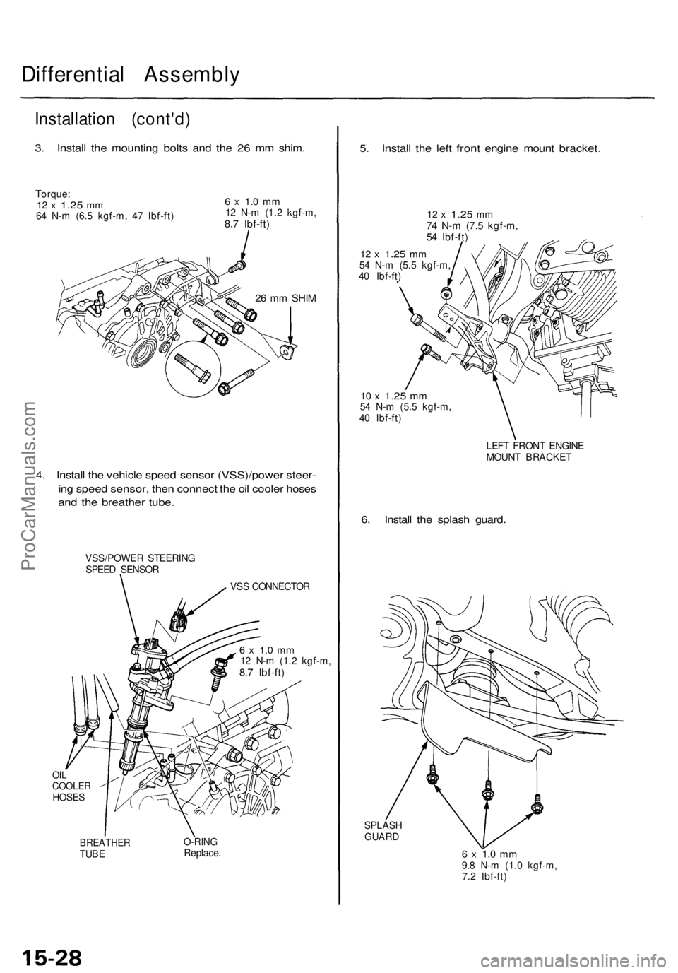
3. Instal l th e mountin g bolt s an d th e 2 6 m m shim .
Torque :12 x 1.2 5 mm64 N- m (6. 5 kgf-m , 4 7 Ibf-ft )
6 x 1. 0 m m12 N- m (1. 2 kgf-m ,8.7 Ibf-ft )
26 m m SHI M
4. Instal l th e vehicl e spee d senso r (VSS)/powe r steer -
in g spee d sensor , the n connec t th e oi l coole r hose s
an d th e breathe r tube .
VSS/POWE R STEERIN G
SPEE D SENSO R
VSS CONNECTO R
6 x 1. 0 m m12 N- m (1. 2 kgf-m ,8.7 Ibf-ft )
OILCOOLE RHOSES
BREATHE RTUBEO-RIN GReplace .
5. Instal l th e lef t fron t engin e moun t bracket .
12 x 1.2 5 mm74 N- m (7. 5 kgf-m ,54 Ibf-ft )
12 x 1.2 5 mm54 N- m (5. 5 kgf-m ,
4 0 Ibf-ft )
10 x 1.2 5 mm54 N- m (5. 5 kgf-m ,
4 0 Ibf-ft )
LEFT FRON T ENGIN E
MOUN T BRACKE T
6. Instal l th e splas h guard .
SPLAS HGUARD
6 x 1. 0 m m9.8 N- m (1. 0 kgf-m ,
7. 2 Ibf-ft )
ProCarManuals.com
Page 1124 of 1771
Driveshafts
Removal
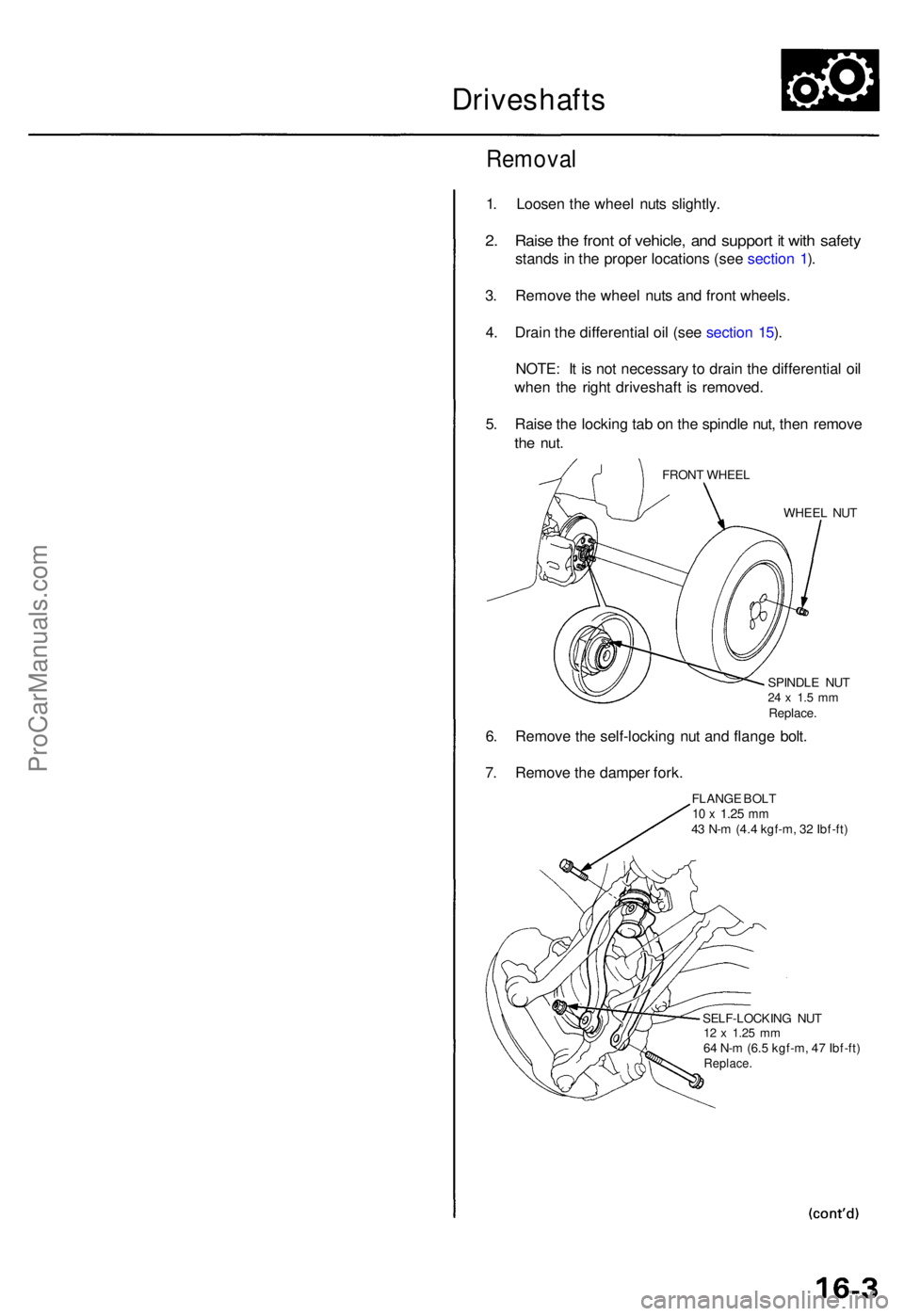
1. Loose n th e whee l nut s slightly .
2. Rais e th e fron t o f vehicle , an d suppor t i t wit h safet y
stand s in th e prope r location s (se e sectio n 1 ).
3 . Remov e th e whee l nut s an d fron t wheels .
4 . Drai n th e differential oil (se e sectio n 15 ).
NOTE : I t i s no t necessar y t o drai n th e differential oil
whe n th e righ t driveshaf t i s removed .
5 . Rais e th e lockin g ta b o n th e spindl e nut , the n remov e
the nut .
FRON T WHEE L
WHEEL NU T
SPINDL E NU T
24 x 1. 5 m mReplace .
6. Remov e th e self-lockin g nu t an d flang e bolt .
7 . Remov e th e dampe r fork .
FLANG E BOL T10 x 1.2 5 mm43 N- m (4. 4 kgf-m , 3 2 Ibf-ft )
SELF-LOCKIN G NU T
12 x 1.2 5 m m64 N- m (6. 5 kgf-m , 4 7 Ibf-ft )Replace .
ProCarManuals.com
Page 1125 of 1771
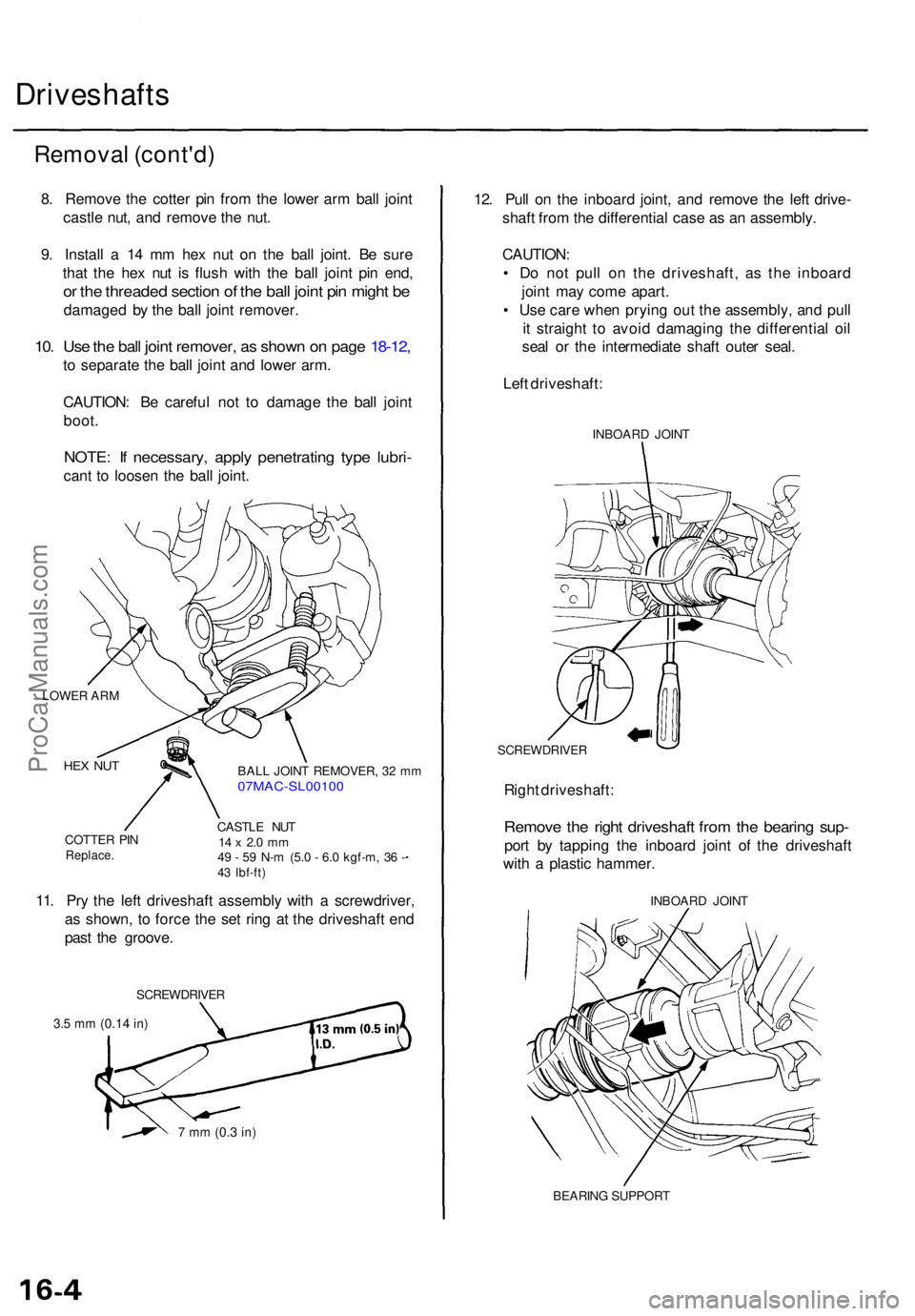
Driveshafts
Removal (cont'd )
8. Remov e th e cotte r pi n fro m th e lowe r ar m bal l join t
castl e nut , an d remov e th e nut .
9 . Instal l a 1 4 m m he x nu t o n th e bal l joint . B e sur e
tha t th e he x nu t i s flus h wit h th e bal l join t pi n end ,
or th e threade d sectio n o f th e bal l join t pi n migh t b e
damage d b y th e bal l join t remover .
10. Us e th e bal l join t remover , a s show n o n pag e 18-12 ,
to separat e th e bal l join t an d lowe r arm .
CAUTION : B e carefu l no t t o damag e th e bal l join t
boot .
NOTE : I f necessary , appl y penetratin g typ e lubri -
cant t o loose n th e bal l joint .
LOWE R AR M
HEX NU T
COTTE R PI NReplace .
BALL JOIN T REMOVER , 3 2 m m07MAC-SL0010 0
CASTLE NU T14 x 2. 0 m m49 - 5 9 N- m (5. 0 - 6. 0 kgf-m , 3 6 -43 Ibf-ft )
11. Pr y th e lef t driveshaf t assembl y wit h a screwdriver ,
a s shown , t o forc e th e se t rin g a t th e driveshaf t en d
pas t th e groove .
SCREWDRIVE R
3.5 m m (0.1 4 in)
7 m m (0. 3 in)
12. Pul l o n th e inboar d joint , an d remov e th e lef t drive -
shaf t fro m th e differential case a s a n assembly .
CAUTION :
• D o no t pul l o n th e driveshaft , a s th e inboar d
join t ma y com e apart .
• Us e car e whe n pryin g ou t th e assembly , an d pul l
i t straigh t t o avoi d damagin g th e differentia l oi l
sea l o r th e intermediat e shaf t oute r seal .
Lef t driveshaft :
INBOARD JOIN T
SCREWDRIVE R
Right driveshaft :
Remove th e righ t driveshaf t fro m th e bearin g sup -
port b y tappin g th e inboar d join t o f th e driveshaf t
wit h a plasti c hammer .
INBOARD JOIN T
BEARIN G SUPPOR T
ProCarManuals.com
Page 1136 of 1771

4. Instal l th e inboar d en d o f th e driveshaf t int o th e dif -
ferentia l o r th e intermediat e shaft .
SET RIN GReplace .Make sur e th e lef t driveshaf t lock s in th e differen -
tia l sid e gea r groove , an d th e inboar d join t sub-axl e
bottom s i n th e differential .
Lef t Driveshaf t
SE T RIN G GROOV E SE
T RIN G
Replace .
Right Driveshaf t
Inser t th e righ t driveshaf t inboar d join t sub-axl e int o
the intermediat e shaf t unti l th e intermediat e shaf tset rin g lock s in th e groov e in th e righ t driveshaft .
5. Instal l th e knuckl e o n th e lowe r arm , the n tighte n
the castl e nu t an d instal l a ne w cotte r pin .
FLANG E BOL T10 x 1.2 5 mm43 N- m (4. 4 kgf-m , 3 2 Ibf-ft )
SELF-LOCKIN G NU T
12 x 1.2 5 mm64 N- m (6. 5 kgf-m , 4 7 Ibf-ft )Replace .
CASTL E NU T
14 x 2. 0 m m49-5 9 N- m (5. 0 - 6. 0 kgf-m ,
36-4 3 Ibf-ft )
6. Instal l th e dampe r for k ove r th e driveshaf t an d ont o
th e lowe r arm . Instal l th e dampe r i n th e dampe r
fork s o th e alignin g ta b i s aligne d wit h th e slo t i n
th e dampe r for k (se e sectio n 18 ).
Loosel y instal l th e flang e bolt s an d th e ne w self -
lockin g nut .
NOTE : Th e bolt s an d nu t shoul d b e tightene d wit h
the vehicle' s weigh t o n th e damper .
Install a ne w spindl e nut , the n tighte n th e nut .
7.
8.
FRON T WHEE L
WHEE L NU T
SPINDL E NU T24 x 1. 5 m mReplace .
9. Instal l th e fron t whee l wit h th e whee l nuts .
NOTE : Befor e installin g th e wheel , clea n th e matin g
surface s o f th e brak e dis c an d th e wheel .
10 . Tighte n th e flang e bolt s an d th e ne w self-lockin g
nu t wit h th e vehicle' s weigh t o n th e damper .
11. Refil l th e transmissio n wit h recommende d flui d (se e
sectio n 14 ).
12 . Chec k th e fron t whee l alignmen t an d adjus t i f nec -
essar y (se e sectio n 18 ).
COTTE R PI N'Replace .On reassembly , ben d th ecotte r pi n a s shown .
SET RIN G GROOV ESIDE GEA R
ProCarManuals.com