differential ACURA TL 1995 Service User Guide
[x] Cancel search | Manufacturer: ACURA, Model Year: 1995, Model line: TL, Model: ACURA TL 1995Pages: 1771, PDF Size: 62.49 MB
Page 443 of 1771
Differential Carrie r
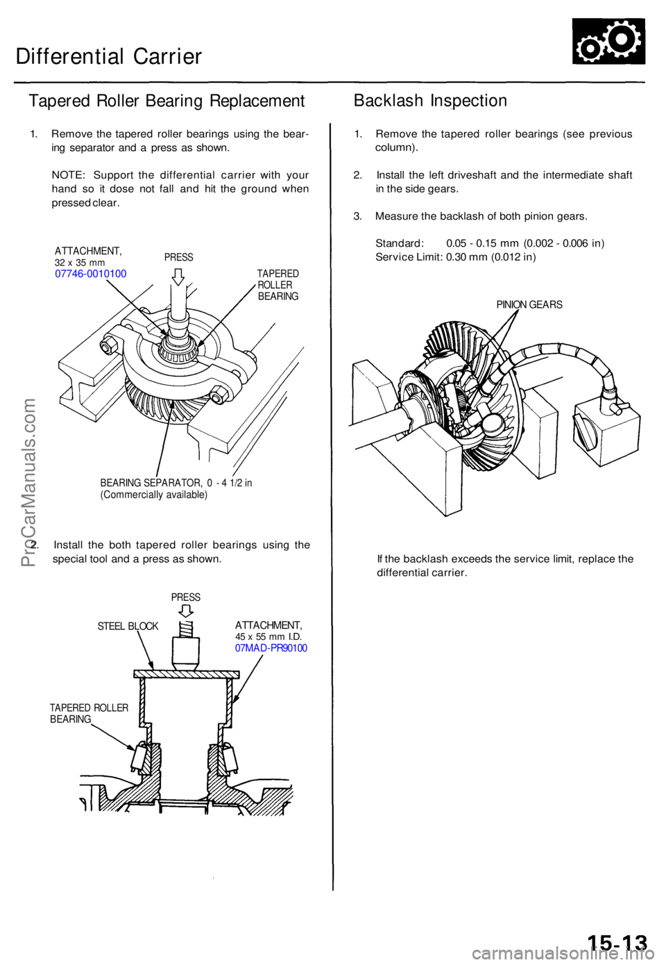
Tapered Rolle r Bearin g Replacemen t
1. Remov e th e tapered roller bearing s usin g th e bear -
in g separato r an d a pres s a s shown .
NOTE : Suppor t th e differentia l carrie r wit h you r
han d s o i t dos e no t fal l an d hi t th e groun d whe n
presse d clear .
ATTACHMENT ,32 x 35 m m07746-001010 0
PRESS
TAPERE DROLLERBEARIN G
BEARIN G SEPARATOR , 0 - 4 1/ 2 in(Commerciall y available )
2. Instal l th e bot h tapere d rolle r bearing s usin g th e
specia l too l an d a pres s a s shown .
STEEL BLOC KATTACHMENT ,45 x 55 m m I.D .07MA D-PR9010 0
TAPERE D ROLLE RBEARIN G
1. Remov e th e tapere d rolle r bearing s (se e previou s
column).
2. Instal l th e lef t driveshaf t an d th e intermediat e shaf t
i n th e sid e gears .
3 . Measur e th e backlas h o f bot h pinio n gears .
Standard : 0.0 5 - 0.1 5 m m (0.00 2 - 0.00 6 in )
Servic e Limit : 0.3 0 m m (0.01 2 in )
PINIO N GEAR S
If th e backlas h exceed s th e servic e limit , replac e th e
differentia l carrier .
PRESS
Backlas h Inspectio n
ProCarManuals.com
Page 444 of 1771
Differential Carrier
Ring Gear Replacement
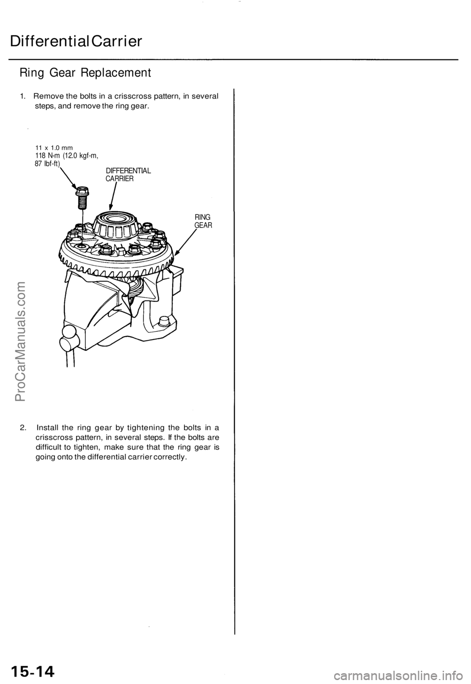
1. Remove the bolts in a crisscross pattern, in several
steps, and remove the ring gear.
11 x 1.0 mm
118 N-m (12.0 kgf-m,
87 Ibf-ft)
DIFFERENTIAL
CARRIER
RING
GEAR
2. Install the ring gear by tightening the bolts in a
crisscross pattern, in several steps. If the bolts are
difficult to tighten, make sure that the ring gear is
going onto the differential carrier correctly.ProCarManuals.com
Page 445 of 1771
Differential Assembl y
Reassembl y
NOTE:
• I f replacemen t i s required , alway s replac e th e driv e
pinion an d rin g gea r a s a set .
• I f th e driv e pinio n an d rin g gea r ar e replaced , chec k th e
heigh t adjustmen t (se e pag e 15-22 ).
• I f replacemen t o f on e o f th e tapere d rolle r bearing s i n
th e driv e pinio n an d i n th e differentia l carrie r i s
required , us e th e sam e mak e bearing s an d replac e bot h
bearing s a t once .
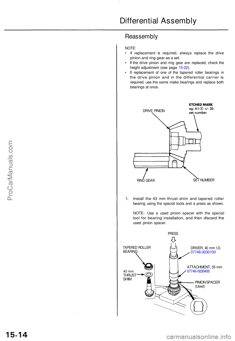
DRIVE PINIO N
RING GEA RSET NUMBE R
1. Instal l th e 4 3 m m thrus t shi m an d tapere d rolle r
bearin g usin g th e specia l tool s an d a pres s a s shown .
NOTE : Us e a use d pinio n space r wit h th e specia l
tool fo r bearin g installation , an d the n discar d th e
use d pinio n spacer .
PRESS
DRIVER , 4 0 m m I.D .07746-003010 0
ATTACHMENT , 3 5 m m0774 6-003040 0
TAPERE D ROLLE RBEARIN G
43 m mTHRUS TSHIMPINIO N SPACE R(Used)
ProCarManuals.com
Page 447 of 1771
Differential Assembl y
Reassembl y (cont'd )
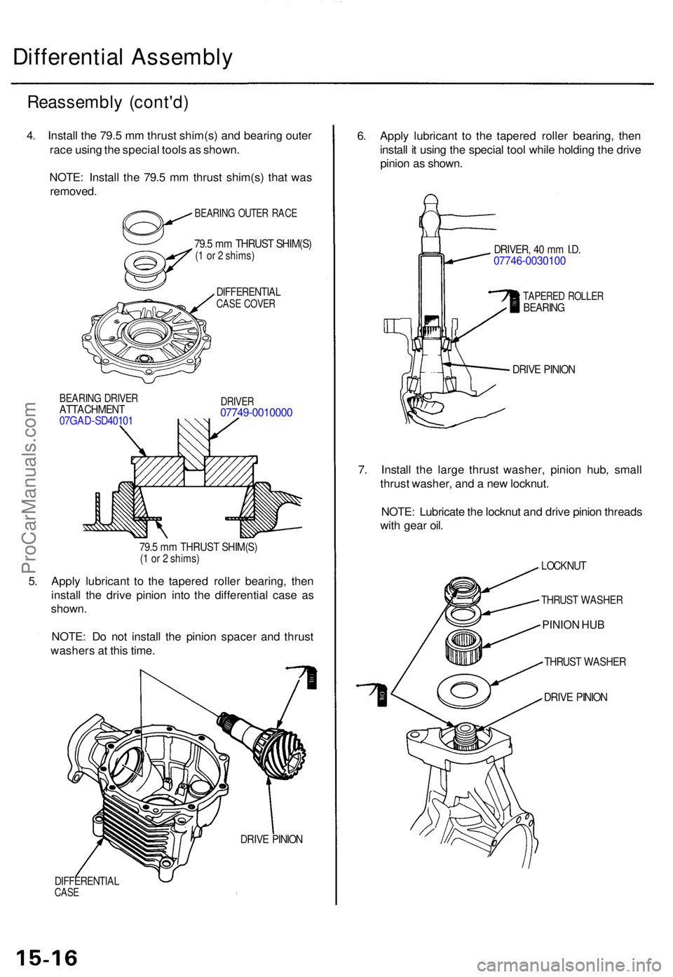
DIFFERENTIA LCASE COVE R
BEARIN G DRIVE RATTACHMEN T07GAD-SD4010 1
DRIVER07749-001000 0
79.5 m m THRUS T SHIM(S )(1 o r 2 shims )
5. Appl y lubrican t t o th e tapere d rolle r bearing , the n
instal l th e driv e pinio n int o th e differentia l cas e a s
shown .
NOTE : D o no t instal l th e pinio n space r an d thrus t
washer s a t thi s time .
DIFFERENTIA LCASE
DRIV E PINIO N
6. Appl y lubrican t t o th e tapere d rolle r bearing , the n
instal l i t usin g th e specia l too l whil e holdin g th e driv e
pinio n a s shown .
DRIVER , 4 0 m m I.D .07746-003010 0
TAPERED ROLLE RBEARIN G
DRIVE PINIO N
7. Instal l th e larg e thrus t washer , pinio n hub , smal l
thrus t washer , an d a ne w locknut .
NOTE : Lubricat e th e locknu t an d driv e pinio n thread s
wit h gea r oil .
LOCKNU T
THRUST WASHE R
PINION HUB
THRUST WASHE R
DRIVE PINIO N
4. Instal l th e 79. 5 m m thrus t shim(s ) an d bearin g oute r
rac e usin g th e specia l tool s a s shown .
NOTE : Instal l th e 79. 5 m m thrus t shim(s ) tha t wa s
removed .
IBEARING OUTE R RAC E
79.5 m m THRUS T SHIM(S )(1 o r 2 shims )
ProCarManuals.com
Page 449 of 1771
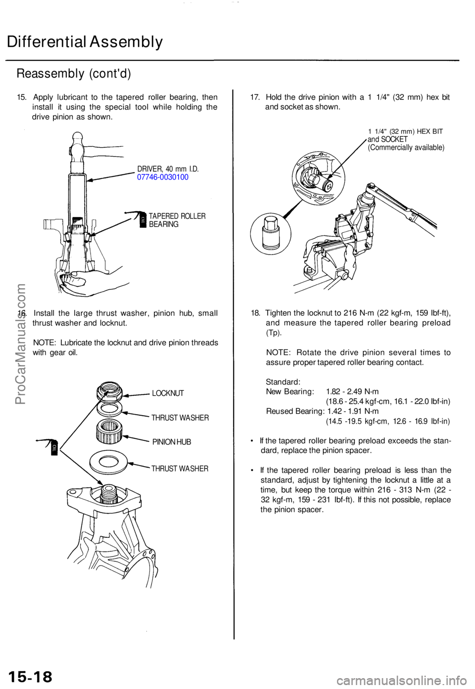
Differential Assembl y
Reassembl y (cont'd )
15. Appl y lubrican t t o th e tapere d rolle r bearing , the n
instal l i t usin g th e specia l too l whil e holdin g th e
driv e pinio n a s shown .
DRIVER , 4 0 m m I.D .07746-003010 0
TAPERED ROLLE RBEARIN G
16. Instal l th e larg e thrus t washer , pinio n hub , smal l
thrus t washe r an d locknut .
NOTE : Lubricat e th e locknu t an d driv e pinio n thread s
wit h gea r oil . 17
. Hol d th e driv e pinio n wit h a 1 1/4 " (3 2 mm ) he x bi t
an d socke t a s shown .
1 1/4" (32 mm ) HE X BI Tand SOCKE T(Commerciall y available )
18. Tighte n th e locknu t t o 21 6 N- m (2 2 kgf-m , 15 9 Ibf-ft) ,
an d measur e th e tapere d rolle r bearin g preloa d
(Tp).
NOTE : Rotat e th e driv e pinio n severa l time s t o
assur e prope r tapere d rolle r bearin g contact .
Standard :
New Bearing : 1.8 2 - 2.4 9 N- m
(18. 6 - 25. 4 kgf-cm , 16. 1 - 22. 0 Ibf-in )
Reuse d Bearing : 1.4 2 - 1.9 1 N- m
(14. 5 -19. 5 kgf-cm , 12. 6 - 16. 9 Ibf-in )
• I f th e tapere d rolle r bearin g preloa d exceed s th e stan -
dard , replac e th e pinio n spacer .
• I f th e tapere d rolle r bearin g preloa d i s les s tha n th e
standard , adjus t b y tightenin g th e locknu t a littl e a t a
time , bu t kee p th e torqu e withi n 21 6 - 31 3 N- m (2 2 -
3 2 kgf-m , 15 9 - 23 1 Ibf-ft) . I f thi s no t possible , replac e
th e pinio n spacer .
LOCKNU T
THRUST WASHE R
PINION HU B
THRUS T WASHE R
ProCarManuals.com
Page 450 of 1771
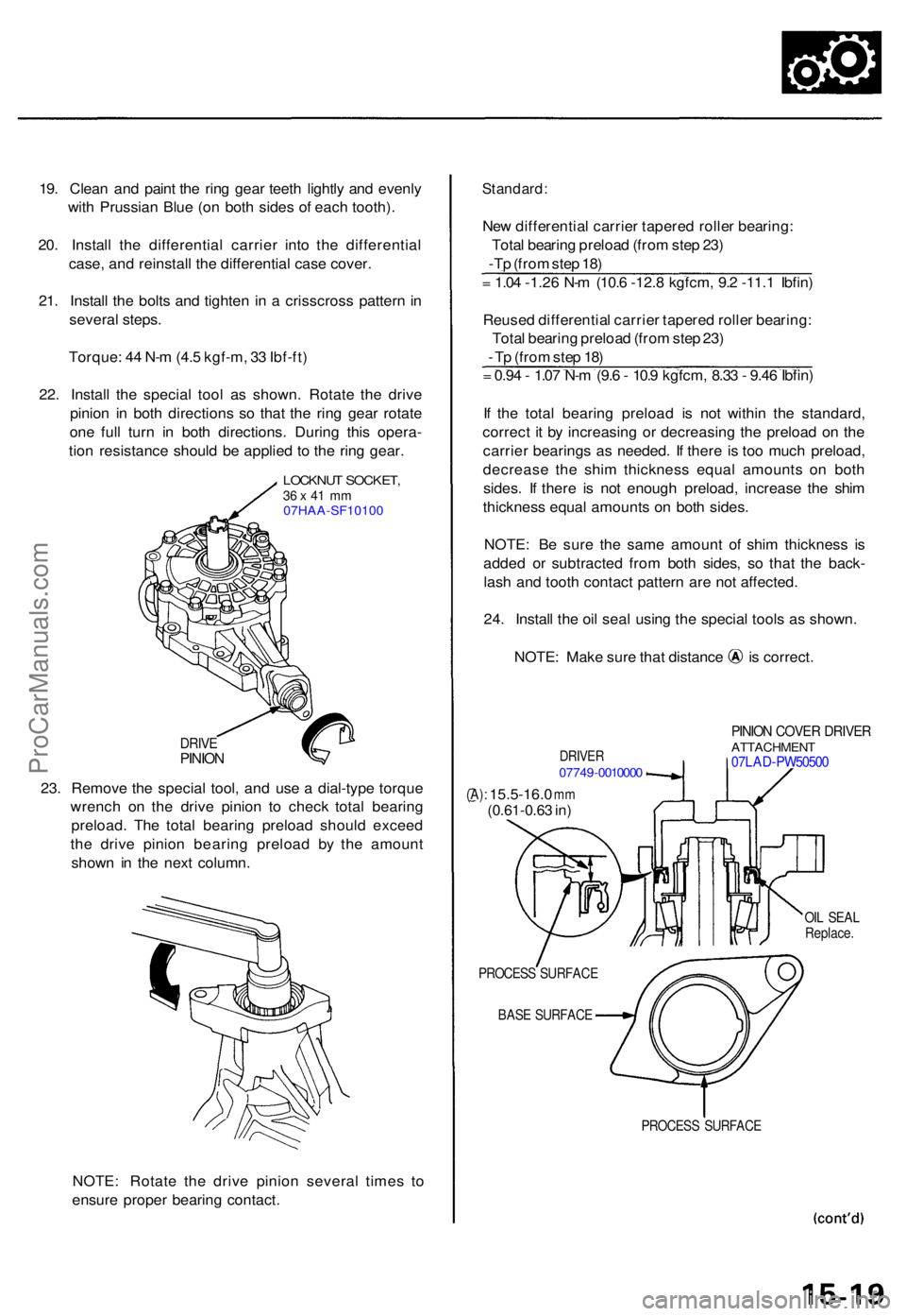
19. Clea n an d pain t th e rin g gea r teet h lightl y an d evenl y
wit h Prussia n Blu e (o n bot h side s o f eac h tooth) .
20 . Instal l th e differentia l carrie r int o th e differentia l
case , an d reinstal l th e differential case cover .
21 . Instal l th e bolt s an d tighte n i n a crisscros s patter n in
severa l steps .
Torque : 4 4 N- m (4. 5 kgf-m , 3 3 Ibf-ft )
22 . Instal l th e specia l too l a s shown . Rotat e th e driv e
pinio n i n bot h direction s s o tha t th e rin g gea r rotat e
on e ful l tur n i n bot h directions . Durin g thi s opera -
tio n resistanc e shoul d b e applie d t o th e rin g gear .
LOCKNU T SOCKET ,36 x 41 m m07HAA-SF10100
DRIV EPINIO N
23. Remov e th e specia l tool , an d us e a dial-typ e torqu e
wrenc h o n th e driv e pinio n t o chec k tota l bearin g
preload . Th e tota l bearin g preloa d shoul d excee d
th e driv e pinio n bearin g preloa d b y th e amoun t
show n i n th e nex t column .
NOTE : Rotat e th e driv e pinio n severa l time s t o
ensur e prope r bearin g contact .
Standard :
New differentia l carrie r tapere d rolle r bearing :
Tota l bearin g preloa d (fro m ste p 23 )
-Tp (fro m ste p 18 )
= 1.0 4 -1.2 6 N- m (10. 6 -12. 8 kgfcm , 9. 2 -11. 1 Ibfin )
Reuse d differentia l carrie r tapere d rolle r bearing :
Tota l bearin g preloa d (fro m ste p 23 )
- T p (fro m ste p 18 )
= 0.9 4 - 1.0 7 N- m (9. 6 - 10. 9 kgfcm , 8.3 3 - 9.4 6 Ibfin )
I f th e tota l bearin g preloa d i s no t withi n th e standard ,
correc t i t b y increasin g o r decreasin g th e preloa d o n th e
carrie r bearing s a s needed . I f ther e i s to o muc h preload ,
decreas e th e shi m thicknes s equa l amount s o n bot h
sides . I f ther e i s no t enoug h preload , increase the shi m
thicknes s equa l amount s o n bot h sides .
NOTE : B e sur e th e sam e amoun t of shi m thicknes s i s
adde d o r subtracte d fro m bot h sides , s o tha t th e back -
las h an d toot h contac t patter n ar e no t affected .
24 . Instal l th e oi l sea l usin g th e specia l tool s a s shown .
NOTE: Mak e sur e tha t distanc e i s correct .
DRIVER07749-001000 0
PINION COVE R DRIVE RATTACHMEN T07LAD-PW5050 0
(A): 15.5-16. 0 mm(0.61-0.6 3 in )
OIL SEA L
Replace .
PROCES S SURFAC E
BAS E SURFAC E
PROCESS SURFAC E
ProCarManuals.com
Page 451 of 1771
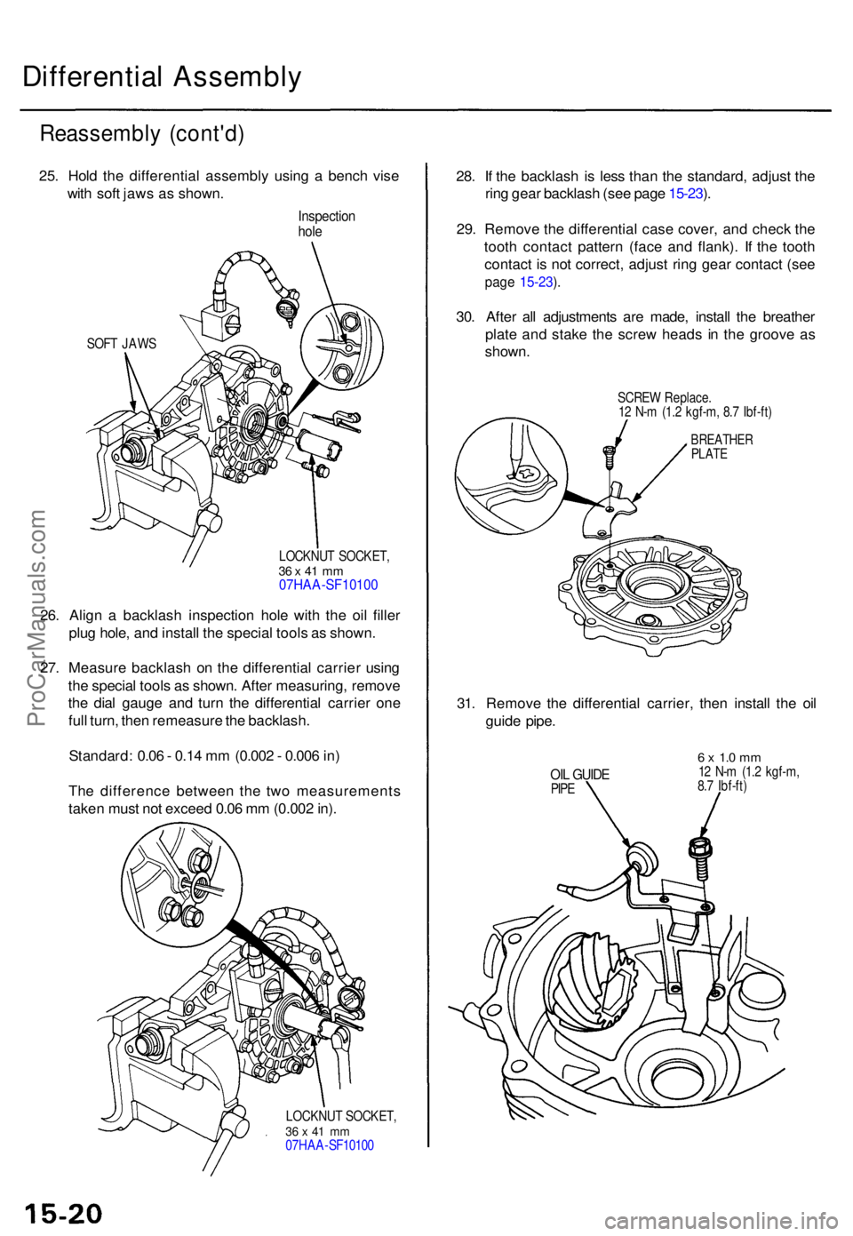
Differential Assembl y
Reassembl y (cont'd )
25. Hol d th e differentia l assembl y usin g a benc h vis e
wit h sof t jaw s a s shown .
Inspectio nhole
SOF T JAW S
LOCKNUT SOCKET ,
36 x 41 m m07HAA-SF1010 0
26. Alig n a backlas h inspectio n hol e wit h th e oi l fille r
plu g hole , an d instal l th e specia l tool s a s shown .
27 . Measur e backlas h o n th e differentia l carrie r usin g
th e specia l tool s a s shown . Afte r measuring , remov e
th e dia l gaug e an d tur n th e differentia l carrie r on e
ful l turn , the n remeasur e th e backlash .
Standard : 0.0 6 - 0.1 4 m m (0.00 2 - 0.00 6 in )
Th e differenc e betwee n th e tw o measurement s
take n mus t no t excee d 0.0 6 m m (0.00 2 in) .
LOCKNU T SOCKET ,36 x 41 m m07HA A-SF1010 0
28. I f th e backlas h i s les s tha n th e standard , adjus t th e
rin g gea r backlas h (se e pag e 15-23 ).
29 . Remov e th e differentia l cas e cover , an d chec k th e
toot h contac t patter n (fac e an d flank) . I f th e toot h
contac t i s no t correct , adjus t rin g gea r contac t (se e
page 15-23 ).
30 . Afte r al l adjustment s ar e made , instal l th e breathe r
plat e an d stak e th e scre w head s i n th e groov e a s
shown .
SCREW Replace .
1 2 N- m (1. 2 kgf-m , 8. 7 Ibf-ft )
BREATHE RPLATE
31. Remov e th e differentia l carrier , the n instal l th e oi l
guid e pipe .
OIL GUID EPIPE
6 x 1. 0 m m12 N- m (1. 2 kgf-m ,
8. 7 Ibf-ft )
ProCarManuals.com
Page 455 of 1771
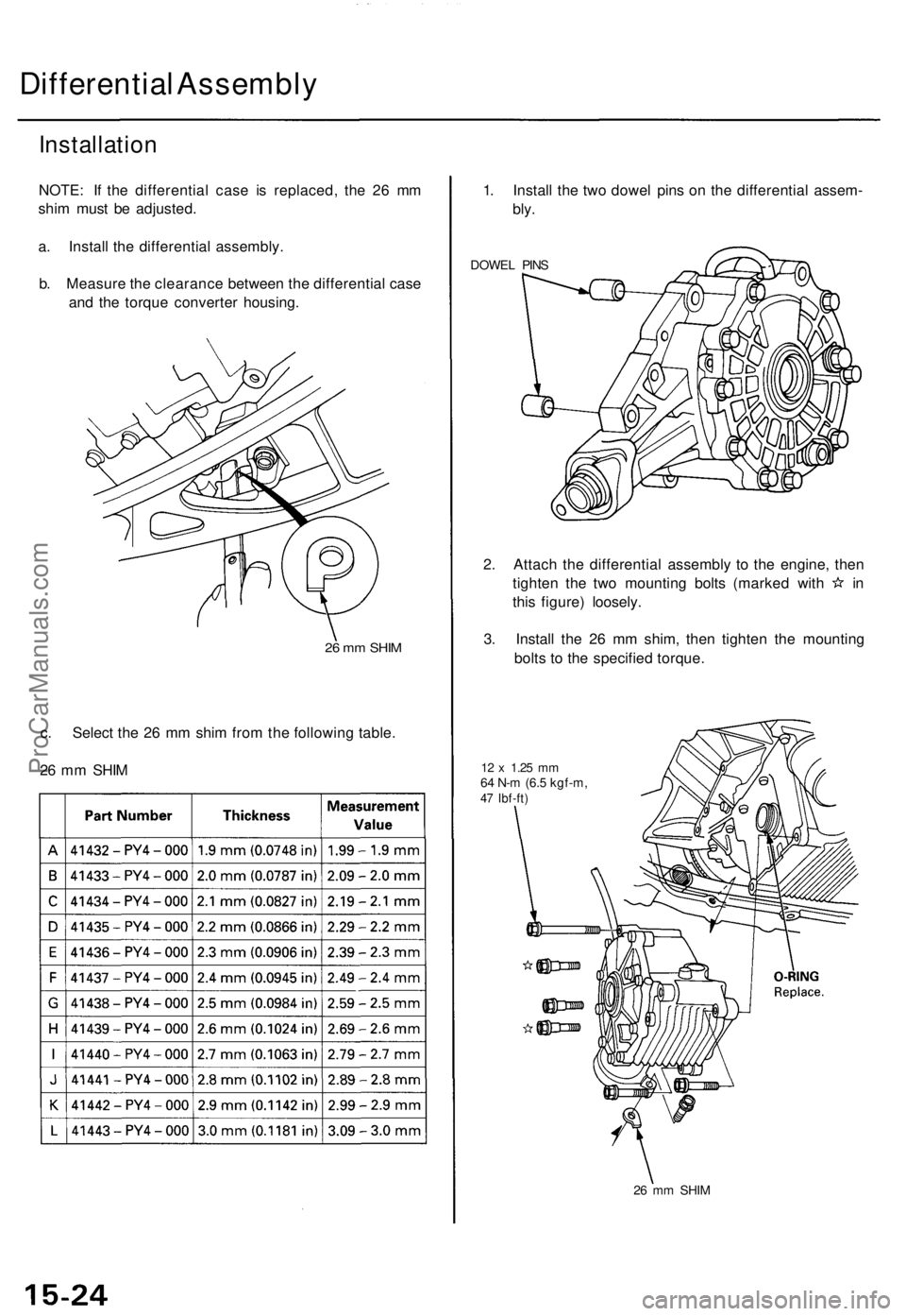
Differential Assembly
Installation
NOTE: If the differential case is replaced, the 26 mm
shim must be adjusted.
a. Install the differential assembly.
b. Measure the clearance between the differential case
and the torque converter housing.
26 mm SHIM
c. Select the 26 mm shim from the following table.
26 mm SHIM
1. Install the two dowel pins on the differential assem-
bly.
DOWEL PINS
2. Attach the differential assembly to the engine, then
tighten the two mounting bolts (marked with in
this figure) loosely.
3. Install the 26 mm shim, then tighten the mounting
bolts to the specified torque.
12 x
1.25
mm
64 N-m (6.5 kgf-m,
47 Ibf-ft)
26 mm SHIMProCarManuals.com
Page 457 of 1771
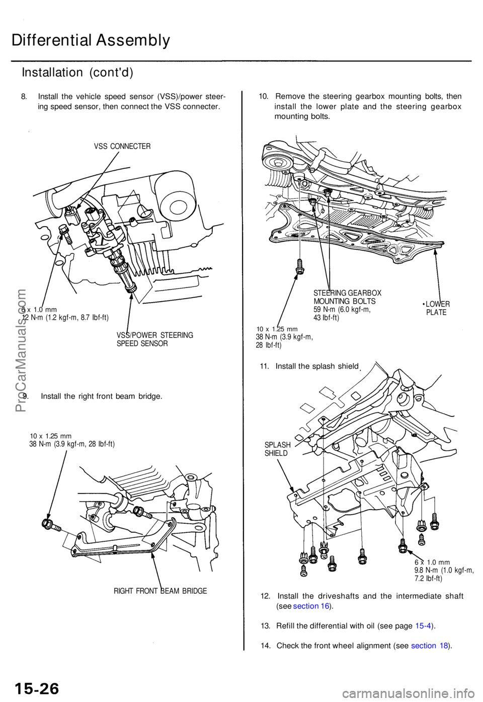
Differential Assembl y
Installatio n (cont'd )
8. Instal l th e vehicl e spee d senso r (VSS)/powe r steer -
in g spee d sensor , the n connec t th e VS S connecter .
VSS CONNECTE R
6 x 1. 0 m m12 N- m (1. 2 kgf-m , 8. 7 Ibf-ft )
VSS/POWE R STEERIN G
SPEE D SENSO R
9. Instal l th e righ t fron t bea m bridge .
10 x 1.2 5 mm38 N- m (3. 9 kgf-m , 2 8 Ibf-ft )
RIGH T FRON T BEA M BRIDG E
10. Remov e th e steerin g gearbo x mountin g bolts , the n
instal l th e lowe r plat e an d th e steerin g gearbo x
mounting bolts .
STEERIN G GEARBO XMOUNTING BOLT S59 N- m (6. 0 kgf-m ,
4 3 Ibf-ft )
10 x 1.2 5 mm38 N- m (3. 9 kgf-m ,28 Ibf-ft )
11. Instal l th e splas h shiel d
SPLAS HSHIELD •
LOWE R
PLATE
6 x 1. 0 m m9.8 N- m (1. 0 kgf-m ,
7. 2 Ibf-ft )
12. Instal l th e driveshaft s an d th e intermediat e shaf t
(se e sectio n 16 ).
13 . Refil l th e differentia l wit h oi l (se e pag e 15-4 ).
14 . Chec k th e fron t whee l alignmen t (se e sectio n 18 ).
ProCarManuals.com
Page 1010 of 1771
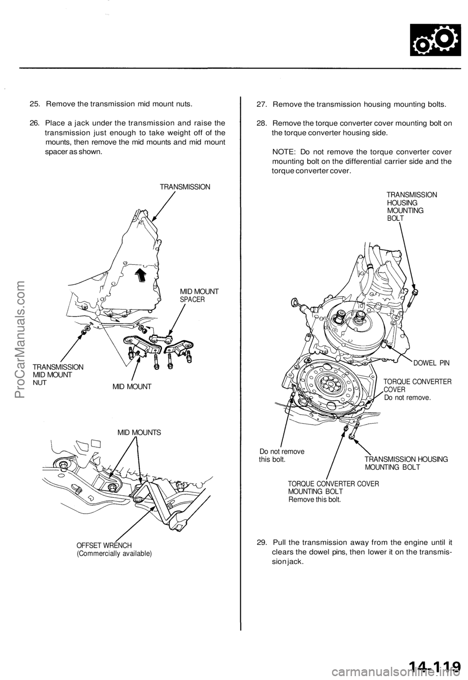
25. Remove the transmission mid mount nuts.
26. Place a jack under the transmission and raise the
transmission just enough to take weight off of the
mounts, then remove the mid mounts and mid mount
spacer as shown.
TRANSMISSION
TRANSMISSION
MID MOUNT
NUT
MID MOUNT
SPACER
MID MOUNT
MID MOUNTS
OFFSET WRENCH
(Commercially available)
27. Remove the transmission housing mounting bolts.
28. Remove the torque converter cover mounting bolt on
the torque converter housing side.
NOTE: Do not remove the torque converter cover
mounting bolt on the differential carrier side and the
torque converter cover.
TRANSMISSION
HOUSING
MOUNTING
BOLT
DOWEL PIN
TORQUE CONVERTER
COVER
Do not remove.
Do not remove
this bolt.
TRANSMISSION HOUSING
MOUNTING BOLT
TORQUE CONVERTER COVER
MOUNTING BOLT
Remove this bolt.
29. Pull the transmission away from the engine until it
clears the dowel pins, then lower it on the transmis-
sion jack.ProCarManuals.com