Fan control ACURA TL 1995 Service Repair Manual
[x] Cancel search | Manufacturer: ACURA, Model Year: 1995, Model line: TL, Model: ACURA TL 1995Pages: 1771, PDF Size: 62.49 MB
Page 562 of 1771
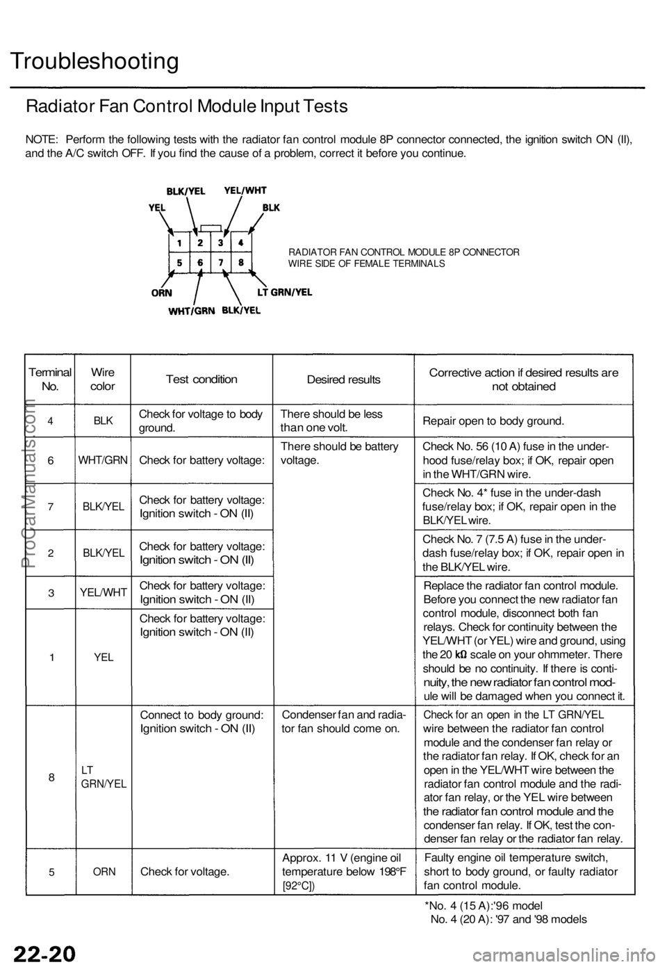
Troubleshooting
Radiator Fan Control Module Input Tests
NOTE: Perform the following tests with the radiator fan control module 8P connector connected, the ignition switch ON (II),
and the A/C switch OFF. If you find the cause of a problem, correct it before you continue.
RADIATOR FAN CONTROL MODULE 8P CONNECTOR
WIRE SIDE OF FEMALE TERMINALS
Terminal
No.
4
6
7
2
3
1
8
5
Wire
color
BLK
WHT/GRN
BLK/YEL
BLK/YEL
YEL/WHT
YEL
LT
GRN/YEL
ORN
Test condition
Check for voltage to body
ground.
Check for battery voltage:
Check for battery voltage:
Ignition switch - ON (II)
Check for battery voltage:
Ignition switch - ON (II)
Check for battery voltage:
Ignition switch - ON (II)
Check for battery voltage:
Ignition switch - ON (II)
Connect to body ground:
Ignition switch - ON (II)
Check for voltage.
Desired results
There should be less
than one volt.
There should be battery
voltage.
Condenser fan and radia-
tor fan should come on.
Approx. 11 V (engine oil
temperature below 198°F
[92°C])
Corrective action if desired results are
not obtained
Repair open to body ground.
Check No. 56 (10 A) fuse in the under-
hood fuse/relay box; if OK, repair open
in the WHT/GRN wire.
Check No. 4* fuse in the under-dash
fuse/relay box; if OK, repair open in the
BLK/YEL wire.
Check No. 7 (7.5 A) fuse in the under-
dash fuse/relay box; if OK, repair open in
the BLK/YEL wire.
Replace the radiator fan control module.
Before you connect the new radiator fan
control module, disconnect both fan
relays. Check for continuity between the
YEL/WHT (or YEL) wire and ground, using
the 20 scale on your ohmmeter. There
should be no continuity. If there is conti-
nuity, the new radiator fan control mod-
ule will be damaged when you connect it.
Check for an open in the LT GRN/YEL
wire between the radiator fan control
module and the condenser fan relay or
the radiator fan relay. If OK, check for an
open in the YEL/WHT wire between the
radiator fan control module and the radi-
ator fan relay, or the YEL wire between
the radiator fan control module and the
condenser fan relay. If OK, test the con-
denser fan relay or the radiator fan relay.
Faulty engine oil temperature switch,
short to body ground, or faulty radiator
fan control module.
*No. 4 (15 A):'96 model
No. 4 (20 A): '97 and '98 modelsProCarManuals.com
Page 570 of 1771

A/C System Service
Performance Test
The performance test will help determine if the air con-
ditioner system is operating within specifications.
Use only service equipment that is U.L.-listed and is cer-
tified to meet the requirements of SAE J2210 to remove
HFC-134a (R-134a) from the air conditioner system.
CAUTION: Exposure to air conditioner refrigerant and
lubricant vapor or mist can irritate eyes, nose and
throat. Avoid breathing the air conditioner refrigerant
and lubricant vapor or mist.
If accidental system discharge occurs, ventilate work
area before resuming service.
R-134a service equipment or vehicle air conditioner sys-
tems should not be pressure tested or leak tested with
compressed air.
Some mixtures of air and R-134a have been
shown to be combustible at elevated pressures and can
result in fire or explosion causing injury or property
damage. Never use compressed air to pressure test R-
134a service equipment or vehicle air conditioner sys-
tems.
Additional health and safety information may be obtained
from the refrigerant and lubricant manufacturers.
1.
2.
Connect a R-134a refrigerant Recover/Recycling/
Charging System to the vehicle, as shown, follow-
ing the equipment manufacturer's instructions.
Insert a thermometer in the center vent outlet.
Determine the relative humidity and air tempera-
ture.
Recovery/Recycling/Charging System
HIGH-PRESSURE
SIDE
LOW-PRESSURE
SIDE
3. Test conditions:
Avoid direct sunlight.
Open hood.
Open front doors.
Set the temperature control dial on MAX COOL,
the mode control switch on VENT and the recir-
culation control switch on RECIRCULATE.
Turn the A/C switch on, and the fan switch on
MAX.
Run the engine at 1,500 rpm.
No driver or passengers in vehicle
4. After running the air conditioning for 10 minutes
under the above test conditions, read the delivery
temperature from the thermometer in the dash vent
and the high and low system pressure from the A/C
gauges.ProCarManuals.com
Page 609 of 1771

Fan Control s
Componen t Locatio n Inde x
ENGIN E COOLAN TTEMPERATUR E (ECT )SWITC H
Test , sectio n 10
Removal , sectio n 1 0
Radiato r Fa n Control :
Whe n th e engine oil temperatur e is abov e approximatel y 198° F (92°C ) afte r th e engin e ha s stopped , th e radiato r fa n wil l ru n
fo r abou t 1 5 minutes . Th e engin e coolan t temperatur e (ECT ) switc h i s i n th e thermosta t housing . Th e engin e oi l tempera -
tur e switc h i s locate d o n th e valv e cover . Th e radiato r fa n contro l modul e is locate d behin d th e glov e box .
ENGIN E OI L TEMPERATUR ESWITCHTest, sectio n 6
Replacement , sectio n 6
Test , page 23-109
Removal , sectio n 1 0 Test
, page 23-109
Removal , sectio n 1 0 Terminals
, page 23-93
Test
, page 23-62
Test, page 23-62
ProCarManuals.com
Page 877 of 1771
PGM-FI System
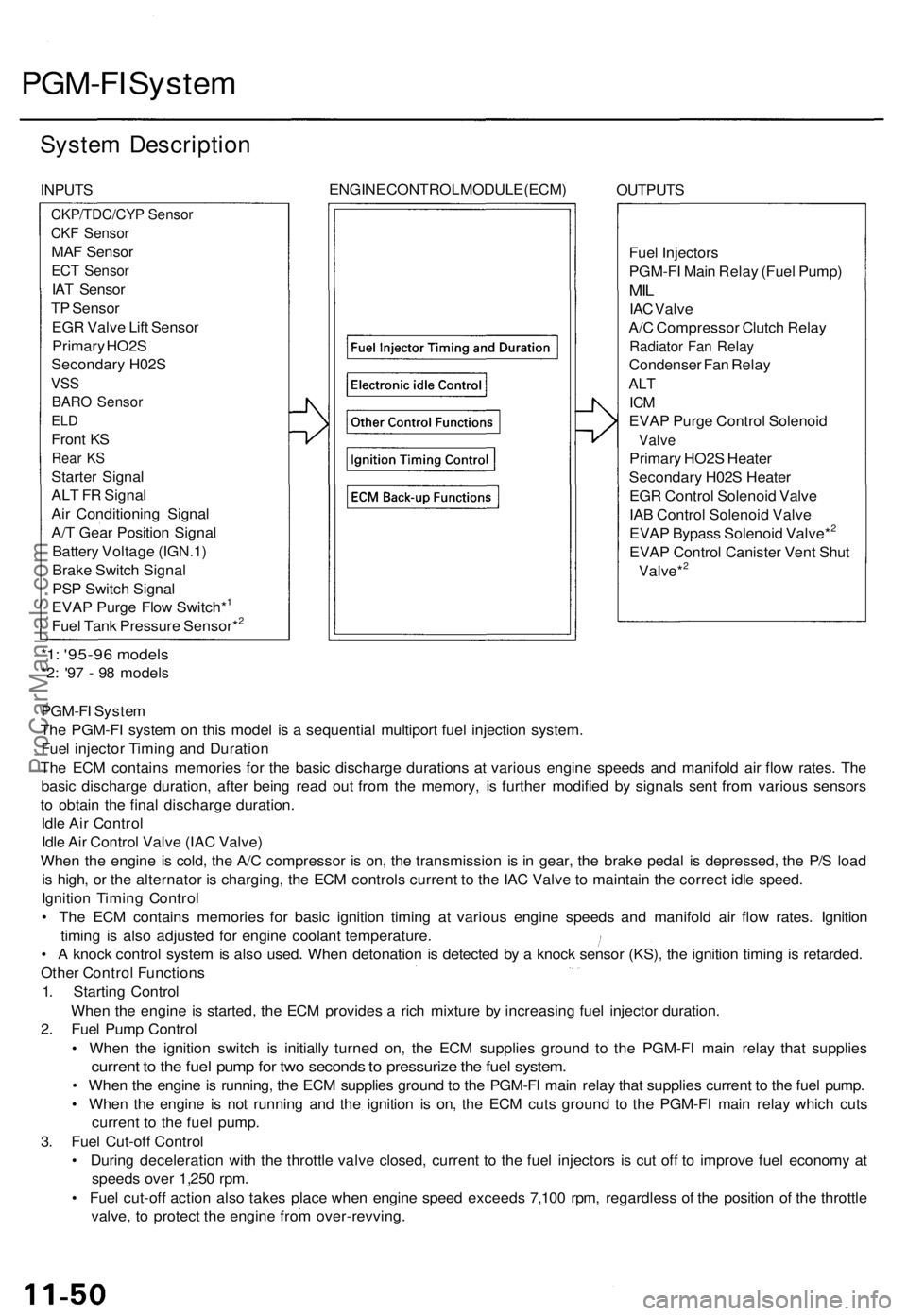
System Description
INPUTS
ENGINE CONTROL MODULE (ECM)
OUTPUTS
Fuel Injectors
PGM-FI Main Relay (Fuel Pump)
MIL
IAC Valve
A/C Compressor Clutch Relay
Radiator Fan Relay
Condenser Fan Relay
ALT
ICM
EVAP Purge Control Solenoid
Valve
Primary HO2S Heater
Secondary H02S Heater
EGR Control Solenoid Valve
IAB Control Solenoid Valve
EVAP Bypass Solenoid Valve*2
EVAP Control Canister Vent Shut
Valve*2
*1: '95-96 models
*2: '97 - 98 models
PGM-FI System
The PGM-FI system on this model is a sequential multiport fuel injection system.
Fuel injector Timing and Duration
The ECM contains memories for the basic discharge durations at various engine speeds and manifold air flow rates. The
basic discharge duration, after being read out from the memory, is further modified by signals sent from various sensors
to obtain the final discharge duration.
Idle Air Control
Idle Air Control Valve (IAC Valve)
When the engine is cold, the A/C compressor is on, the transmission is in gear, the brake pedal is depressed, the P/S load
is high, or the alternator is charging, the ECM controls current to the IAC Valve to maintain the correct idle speed.
Ignition Timing Control
• The ECM contains memories for basic ignition timing at various engine speeds and manifold air flow rates. Ignition
timing is also adjusted for engine coolant temperature.
• A knock control system is also used. When detonation is detected by a knock sensor (KS), the ignition timing is retarded.
Other Control Functions
1. Starting Control
When the engine is started, the ECM provides a rich mixture by increasing fuel injector duration.
2. Fuel Pump Control
• When the ignition switch is initially turned on, the ECM supplies ground to the PGM-FI main relay that supplies
current to the fuel pump for two seconds to pressurize the fuel system.
• When the engine is running, the ECM supplies ground to the PGM-FI main relay that supplies current to the fuel pump.
• When the engine is not running and the ignition is on, the ECM cuts ground to the PGM-FI main relay which cuts
current to the fuel pump.
3. Fuel Cut-off Control
• During deceleration with the throttle valve closed, current to the fuel injectors is cut off to improve fuel economy at
speeds over 1,250 rpm.
• Fuel cut-off action also takes place when engine speed exceeds 7,100 rpm, regardless of the position of the throttle
valve, to protect the engine from over-revving.
CKP/TDC/CYP Sensor
CKF Sensor
MAF Sensor
ECT Sensor
IAT Sensor
TP Sensor
EGR Valve Lift Sensor
Primary HO2S
Secondary H02S
VSS
BARO Sensor
ELD
Front KS
Rear KS
Starter Signal
ALT FR Signal
Air Conditioning Signal
A/T Gear Position Signal
Battery Voltage (IGN.1)
Brake Switch Signal
PSP Switch Signal
EVAP Purge Flow Switch*1
Fuel Tank Pressure Sensor*2ProCarManuals.com
Page 1497 of 1771
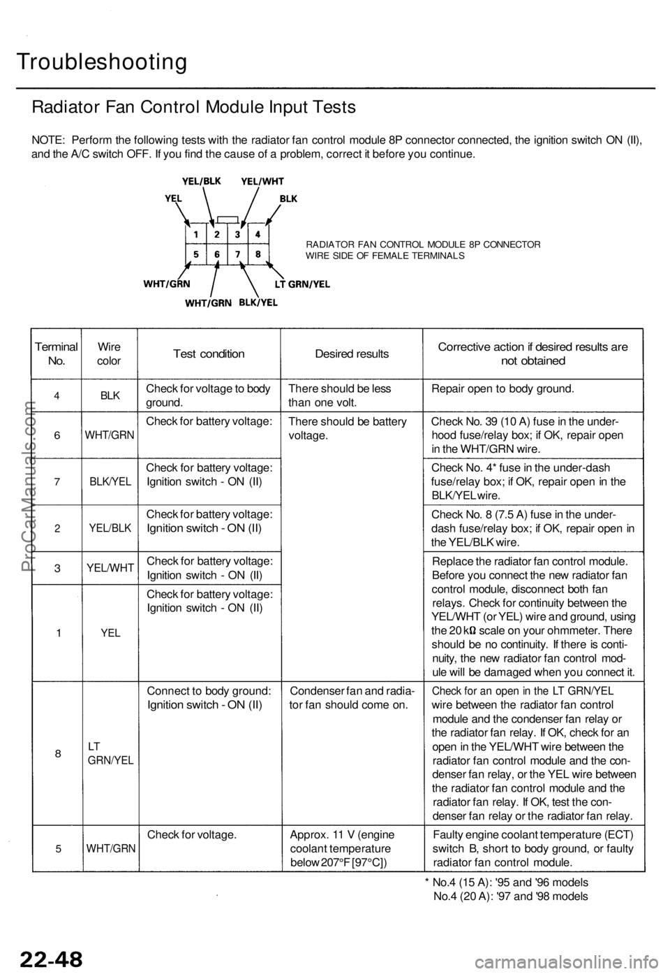
Troubleshooting
Radiator Fan Control Module Input Tests
NOTE: Perform the following tests with the radiator fan control module 8P connector connected, the ignition switch ON (II),
and the A/C switch OFF. If you find the cause of a problem, correct it before you continue.
RADIATOR FAN CONTROL MODULE 8P CONNECTOR
WIRE SIDE OF FEMALE TERMINALS
Terminal
No.
4
6
7
2
3
1
8
5
Wire
color
BLK
WHT/GRN
BLK/YEL
YEL/BLK
YEL/WHT
YEL
LT
GRN/YEL
WHT/GRN
Test condition
Check for voltage to body
ground.
Check for battery voltage:
Check for battery voltage:
Ignition switch - ON (II)
Check for battery voltage:
Ignition switch - ON (II)
Check for battery voltage:
Ignition switch - ON (II)
Check for battery voltage:
Ignition switch - ON (II)
Connect to body ground:
Ignition switch - ON (II)
Check for voltage.
Desired results
There should be less
than one volt.
There should be battery
voltage.
Condenser fan and radia-
tor fan should come on.
Approx. 11 V (engine
coolant temperature
below 207°F [97°C])
Corrective action if desired results are
not obtained
Repair open to body ground.
Check No. 39 (10 A) fuse in the under-
hood fuse/relay box; if OK, repair open
in the WHT/GRN wire.
Check No. 4* fuse in the under-dash
fuse/relay box; if OK, repair open in the
BLK/YEL wire.
Check No. 8 (7.5 A) fuse in the under-
dash fuse/relay box; if OK, repair open in
the YEL/BLK wire.
Replace the radiator fan control module.
Before you connect the new radiator fan
control module, disconnect both fan
relays. Check for continuity between the
YEL/WHT (or YEL) wire and ground, using
the 20 k scale on your ohmmeter. There
should be no continuity. If there is conti-
nuity, the new radiator fan control mod-
ule will be damaged when you connect it.
Check for an open in the LT GRN/YEL
wire between the radiator fan control
module and the condenser fan relay or
the radiator fan relay. If OK, check for an
open in the YEL/WHT wire between the
radiator fan control module and the con-
denser fan relay, or the YEL wire between
the radiator fan control module and the
radiator fan relay. If OK, test the con-
denser fan relay or the radiator fan relay.
Faulty engine coolant temperature (ECT)
switch B, short to body ground, or faulty
radiator fan control module.
* No.4 (15 A): '95 and '96 models
No.4 (20 A): '97 and '98 modelsProCarManuals.com
Page 1540 of 1771
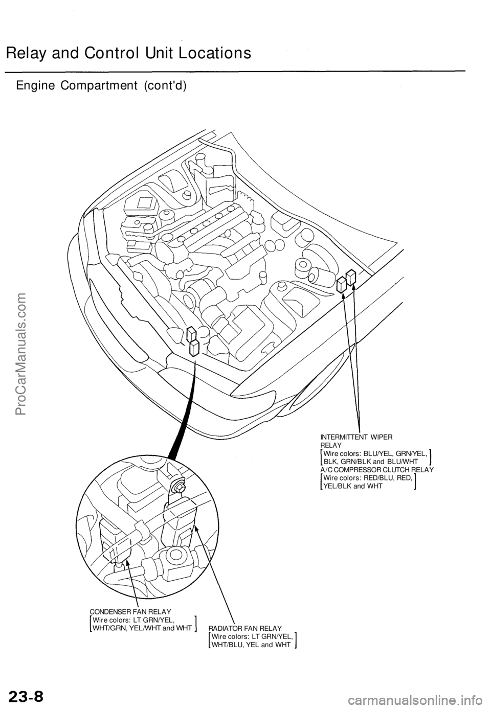
Relay and Control Unit Locations
Engine Compartment (cont'd)
INTERMITTENT WIPER
RELAY
Wire colors: BLU/YEL, GRN/YEL,
BLK, GRN/BLK and BLU/WHT
A/C COMPRESSOR CLUTCH RELAY
Wire colors: RED/BLU, RED,
YEL/BLK and WHT
CONDENSER FAN RELAY
Wire colors: LT GRN/YEL,
WHT/GRN, YEL/WHT and WHT
RADIATOR FAN RELAY
Wire colors: LT GRN/YEL,
WHT/BLU, YEL and WHTProCarManuals.com
Page 1543 of 1771
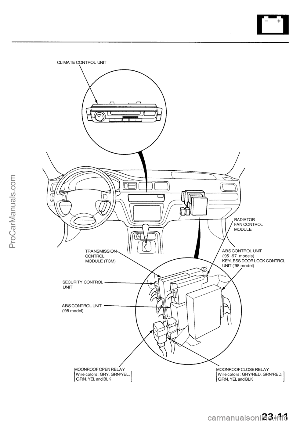
CLIMATE CONTROL UNIT
RADIATOR
FAN CONTROL
MODULE
ABS CONTROL UNIT
('95 -97 models)
KEYLESS DOOR LOCK CONTROL
UNIT ('98 model)
SECURITY CONTROL
UNIT
ABS CONTROL UNIT
('98 model)
MOONROOF OPEN RELAY
Wire colors: GRY, GRN/YEL,
GRN,
YEL and BLK
MOONROOF CLOSE RELAY
Wire colors: GRY/RED, GRN/RED,
GRN,
YEL and BLK
TRANSMISSION
CONTROL
MODULE (TCM)ProCarManuals.com
Page 1589 of 1771
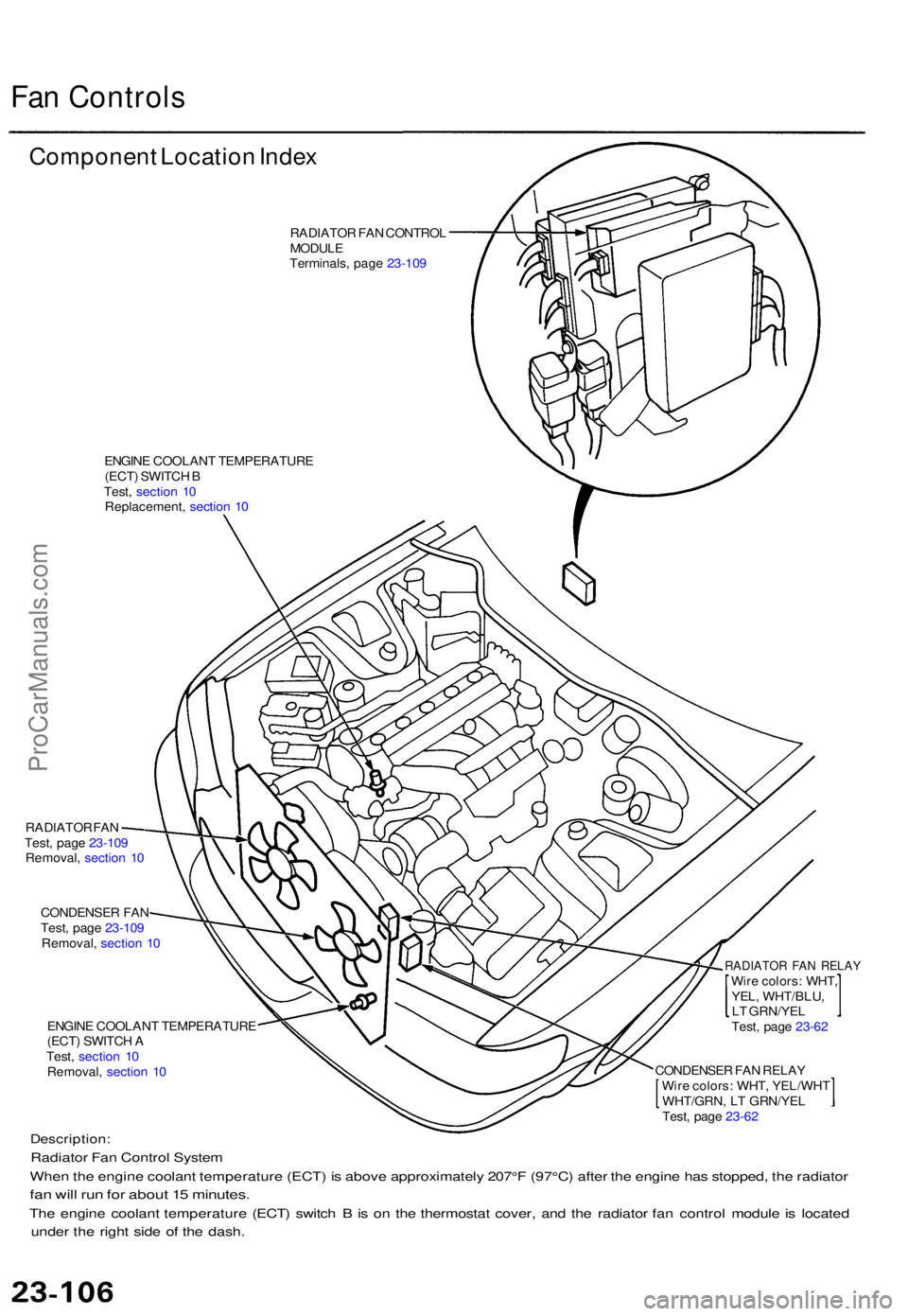
Fan Control s
Componen t Locatio n Inde x
RADIATO R FA N CONTRO L
MODUL E
Terminals , pag e 23-10 9
ENGIN E COOLAN T TEMPERATUR E
(ECT ) SWITC H B
Test , sectio n 1 0
Replacement , sectio n 1 0
RADIATO R FA N
Test , pag e 23-10 9
Removal , sectio n 1 0
CONDENSE R FA N
Test , pag e 23-10 9
Removal , sectio n 1 0
ENGIN E COOLAN T TEMPERATUR E
(ECT ) SWITC H A
Test , sectio n 1 0
Removal , sectio n 1 0
RADIATO R FA N RELA YWire colors : WHT ,
YEL , WHT/BLU ,
L T GRN/YE L
Test , pag e 23-6 2
Description :
Radiator Fa n Contro l Syste m
Whe n th e engin e coolan t temperatur e (ECT ) i s abov e approximatel y 207° F (97°C ) afte r th e engin e ha s stopped , th e radiato r
fan wil l ru n fo r abou t 1 5 minutes .
The engin e coolan t temperatur e (ECT ) switc h B is o n th e thermosta t cover , an d th e radiato r fa n contro l modul e is locate d
unde r th e righ t sid e o f th e dash .
CONDENSE R FA N RELA Y
Wir e colors : WHT , YEL/WH T
WHT/GRN , L T GRN/YE L
Test , pag e 23-6 2
ProCarManuals.com
Page 1590 of 1771

Fan Controls
Troubleshooting
NOTE: The numbers in the table show the troubleshooting sequence.ProCarManuals.com