oil ACURA TL 1995 Service Repair Manual
[x] Cancel search | Manufacturer: ACURA, Model Year: 1995, Model line: TL, Model: ACURA TL 1995Pages: 1771, PDF Size: 62.49 MB
Page 28 of 1771
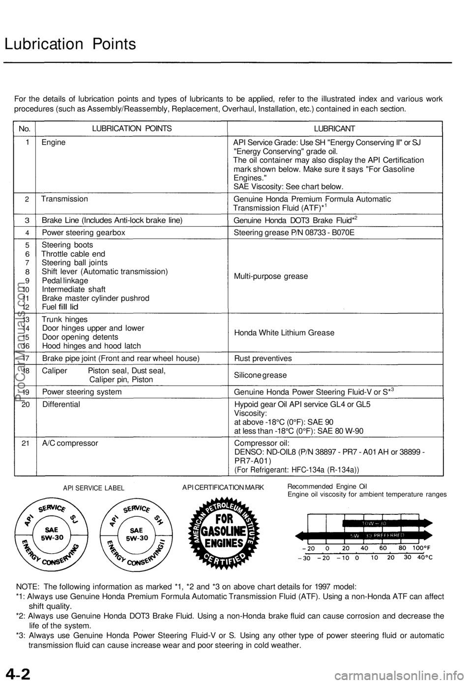
Lubrication Points
For the details of lubrication points and types of lubricants to be applied, refer to the illustrated index and various work
procedures (such as Assembly/Reassembly, Replacement, Overhaul, Installation, etc.) contained in each section.
No.
1
2
3
4
5
6
7
8
9
10
11
12
13
14
15
16
17
18
19
20
21
LUBRICATION POINTS
Engine
Transmission
Brake Line (Includes Anti-lock brake line)
Power steering gearbox
Steering boots
Throttle cable end
Steering ball joints
Shift lever (Automatic transmission)
Pedal linkage
Intermediate shaft
Brake master cylinder pushrod
Fuel
fill
lid
Trunk hinges
Door hinges upper and lower
Door opening detents
Hood hinges and hood latch
Brake pipe joint (Front and rear wheel house)
Caliper Piston seal, Dust seal,
Caliper pin, Piston
Power steering system
Differential
A/C compressor
LUBRICANT
API Service Grade: Use SH "Energy Conserving II" or SJ
"Energy Conserving" grade oil.
The oil container may also display the API Certification
mark shown below. Make sure it says "For Gasoline
Engines."
SAE Viscosity: See chart below.
Genuine Honda Premium Formula Automatic
Transmission Fluid (ATF)*1
Genuine Honda DOT3 Brake Fluid*2
Steering grease P/N 08733 - B070E
Multi-purpose grease
Honda White Lithium Grease
Rust preventives
Silicone grease
Genuine Honda Power Steering Fluid-V or S*3
Hypoid gear Oil API service GL4 or GL5
Viscosity:
at above -18°C (0°F): SAE 90
at less than -18°C (0°F): SAE 80 W-90
Compressor oil:
DENSO: ND-OIL8 (P/N 38897 - PR7 - A01 AH or 38899 -
PR7-A01)
(For Refrigerant: HFC-134a (R-134a))
API SERVICE LABEL
API CERTIFICATION MARK
Recommended Engine Oil
Engine oil viscosity for ambient temperature ranges
NOTE: The following information as marked *1, *2 and *3 on above chart details for 1997 model:
*1: Always use Genuine Honda Premium Formula Automatic Transmission Fluid (ATF). Using a non-Honda ATF can affect
shift quality.
*2: Always use Genuine Honda DOT3 Brake Fluid. Using a non-Honda brake fluid can cause corrosion and decrease the
life of the system.
*3: Always use Genuine Honda Power Steering Fluid-V or S. Using any other type of power steering fluid or automatic
transmission fluid can cause increase wear and poor steering in cold weather.ProCarManuals.com
Page 48 of 1771
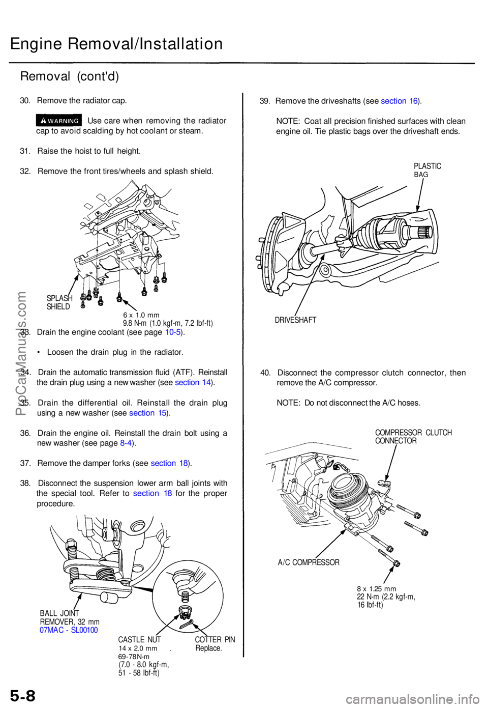
Engine Removal/Installatio n
Removal (cont'd )
30. Remov e th e radiato r cap .
Us e car e whe n removin g th e radiato r
ca p to avoi d scaldin g b y ho t coolan t o r steam .
31 . Rais e th e hois t t o ful l height .
32 . Remov e th e fron t tires/wheel s an d splas h shield .
SPLAS H
SHIEL D
6 x 1. 0 m m9.8 N- m (1. 0 kgf-m , 7. 2 Ibf-ft )33. Drai n th e engin e coolan t (se e pag e 10-5 ).
• Loose n th e drai n plu g i n th e radiator .
34 . Drai n th e automati c transmissio n flui d (ATF) . Reinstal l
th e drai n plu g usin g a ne w washe r (se e sectio n 14 ).
35 . Drai n th e differentia l oil . Reinstal l th e drai n plu g
usin g a ne w washe r (se e sectio n 15 ).
36 . Drai n th e engin e oil . Reinstal l th e drai n bol t usin g a
ne w washe r (se e pag e 8-4 ).
37 . Remov e th e dampe r fork s (se e sectio n 18 ).
38 . Disconnec t th e suspensio n lowe r ar m bal l joint s wit h
th e specia l tool . Refe r t o sectio n 1 8 fo r th e prope r
procedure .
BALL JOIN T
REMOVER , 3 2 m m
07MA C - SL0010 0
CASTLE NU T14 x 2. 0 m m69 - 7 8 N- m(7. 0 - 8. 0 kgf-m ,
5 1 - 5 8 Ibf-ft ) COTTE
R PI N
Replace .
39. Remov e th e driveshaft s (se e sectio n 16 ).
NOTE : Coa t al l precisio n finishe d surface s wit h clea n
engin e oil . Ti e plasti c bag s ove r th e driveshaf t ends .
PLASTI CBAG
DRIVESHAF T
40. Disconnec t th e compresso r clutc h connector , the n
remov e th e A/ C compressor .
NOTE : D o no t disconnec t th e A/ C hoses .
COMPRESSO R CLUTC H
CONNECTO R
A/ C COMPRESSO R
8 x 1.2 5 mm22 N- m (2. 2 kgf-m ,
1 6 Ibf-ft )
ProCarManuals.com
Page 60 of 1771
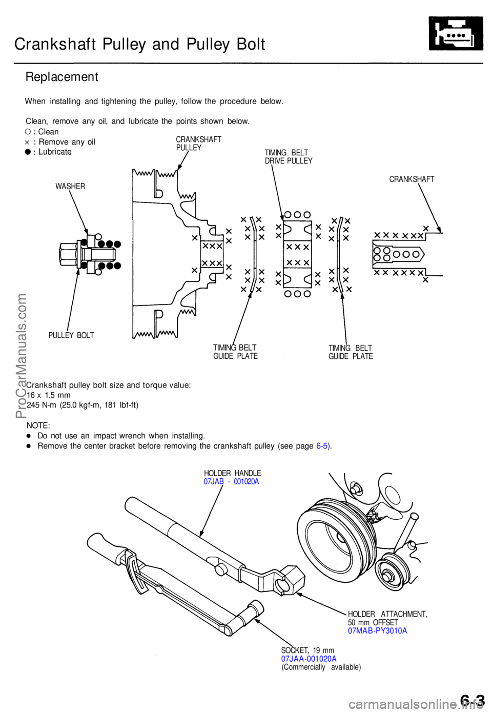
Crankshaft Pulle y an d Pulle y Bol t
Replacemen t
WASHER
PULLE Y BOL T CRANKSHAF
T
TIMING BEL TGUID E PLAT E TIMIN
G BEL T
GUID E PLAT E
Crankshaf t pulle y bol t siz e an d torqu e value :
16 x 1. 5 m m
245 N- m (25. 0 kgf-m , 18 1 Ibf-ft )
NOTE :
D o no t us e a n impac t wrenc h whe n installing .
Remov e th e cente r bracke t befor e removin g th e crankshaf t pulle y (se e pag e 6-5 ).
HOLDE R HANDL E
07JA B - 001020 A
HOLDER ATTACHMENT ,
5 0 m m OFFSE T
07MAB-PY3010 A
SOCKET, 1 9 m m07JAA-001020 A(Commercially available )
When installin g an d tightenin g th e pulley , follo w th e procedur e below .
Clean , remov e an y oil , an d lubricat e th e point s show n below .
TIMING BEL T
DRIV E PULLE Y
CRANKSHAF
T
PULLE Y
Clean
Remov e an y oi l
Lubricat e
ProCarManuals.com
Page 64 of 1771
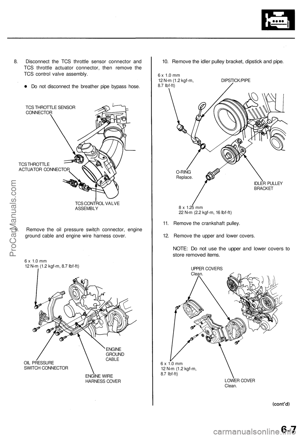
8. Disconnect the TCS throttle sensor connector and
TCS throttle actuator connector, then remove the
TCS control valve assembly.
Do not disconnect the breather pipe bypass hose.
TCS THROTTLE SENSOR
CONNECTOR
TCS THROTTLE
ACTUATOR CONNECTOR
TCS CONTROL VALVE
ASSEMBLY
9. Remove the oil pressure switch connector, engine
ground cable and engine wire harness cover.
6 x 1.0 mm
12 N-m (1.2 kgf-m, 8.7 Ibf-ft)
OIL PRESSURE
SWITCH CONNECTOR
ENGINE
GROUND
CABLE
ENGINE WIRE
HARNESS COVER
10. Remove the idler pulley bracket, dipstick and pipe.
6 x 1.0 mm
12 N-m (1.2 kgf-m,
8.7 Ibf-ft)
DIPSTICK/PIPE
8 x
1.25
mm
22 N-m (2.2 kgf-m, 16 Ibf-ft)
11. Remove the crankshaft pulley.
12. Remove the upper and lower covers.
NOTE: Do not use the upper and lower covers to
store removed items.
UPPER COVERS
Clean.
6 x 1.0 mm
12 N-m (1.2 kgf-m,
8.7 Ibf-ft)
LOWER COVER
Clean.
IDLER PULLEY
BRACKET
O-RING
Replace.ProCarManuals.com
Page 71 of 1771
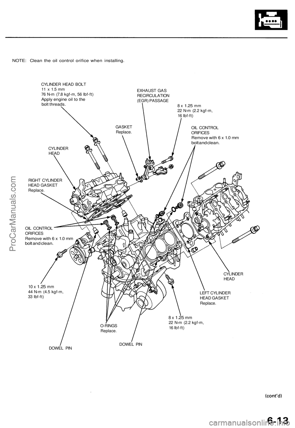
NOTE: Clean the oil control orifice when installing.
CYLINDER HEAD BOLT
11 x 1.5 mm
76 N-m (7.8 kgf-m, 56 Ibf-ft)
Apply engine oil to the
bolt threads.
EXHAUST GAS
RECIRCULATION
(EGR) PASSAGE
8 x
1.25
mm
22 N-m (2.2 kgf-m,
16 Ibf-ft)
OIL CONTROL
ORIFICES
Remove with 6 x 1.0 mm
bolt and clean.
RIGHT CYLINDER
HEAD GASKET
Replace.
OIL CONTROL
ORIFICES
Remove with 6 x 1.0 mm
bolt and clean.
CYLINDER
HEAD
10 x
1.25
mm
44 N-m (4.5 kgf-m,
33 Ibf-ft)
LEFT CYLINDER
HEAD GASKET
Replace.
8 x
1.25
mm
22 N-m (2.2 kgf-m,
16 Ibf-ft)
DOWEL PIN
DOWEL PIN
O-RINGS
Replace.
GASKET
Replace.
CYLINDER
HEADProCarManuals.com
Page 72 of 1771
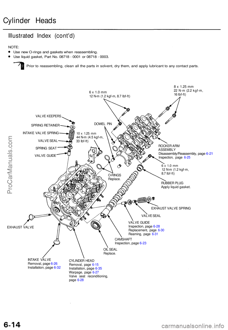
Cylinder Head s
Illustrate d Inde x (cont'd )
NOTE:
Use ne w O-ring s an d gasket s whe n reassembling .
Use liqui d gasket , Par t No . 0871 8 - 000 1 o r 0871 8 - 0003 .
Prior t o reassembling , clea n al l th e part s in solvent , dr y them , an d appl y lubrican t t o an y contac t parts .
6 x 1.0 mm12 N- m (1. 2 kgf-m , 8. 7 Ibf-ft )
8 x 1.2 5 mm22 N- m (2. 2 kgf-m ,
1 6 Ibf-ft )
VALV E KEEPER S
SPRING RETAINE R
INTAK E VALV E SPRIN G
VALV E SEA L
10 x 1.2 5 mm44 N- m (4. 5 kgf-m ,
3 3 Ibf-ft )
SPRIN G SEA T
VALV E GUID E
EXHAUS T VALV E ROCKE
R AR M
ASSEMBL YDisassembly/Reassembly , pag e 6-2 1Inspection , pag e 6-2 5
6 x 1. 0 m m12 N- m (1. 2 kgf-m ,
8. 7 Ibf-ft )
RUBBE R PLU G
Apply liqui d gasket .
VALVE GUID EInspection , pag e 6-2 8Replacement , pag e 6-3 0
Reaming , pag e 6-3 1
CAMSHAF T
Inspection, pag e 6-2 3
OIL SEA LReplace .
INTAKE VALV ERemoval , pag e 6-2 6Installation , pag e 6-3 2
CYLINDE R HEA D
Removal , pag e 6-1 5
Installation , pag e 6-3 5Warpage , pag e 6-2 7
Valv e sea t reconditioning ,
pag e 6-2 8 VALV
E SEA L
EXHAUS
T VALV E SPRIN G
O-RING
S
Replace .
DOWE
L PI N
ProCarManuals.com
Page 75 of 1771
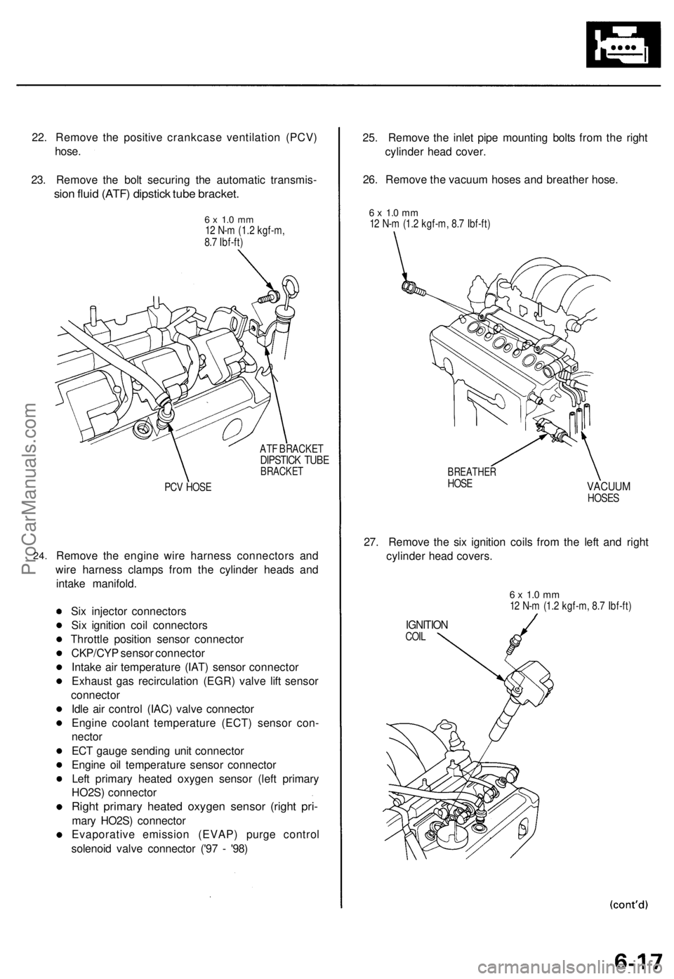
22. Remove the positive crankcase ventilation (PCV)
hose.
23. Remove the bolt securing the automatic transmis-
sion fluid (ATF) dipstick tube bracket.
6 x 1.0 mm
12 N-m (1.2 kgf-m,
8.7 Ibf-ft)
ATF BRACKET
DIPSTICK TUBE
BRACKET
PCV HOSE
24.
Remove the engine wire harness connectors and
wire harness clamps from the cylinder heads and
intake manifold.
Six injector connectors
Six ignition coil connectors
Throttle position sensor connector
CKP/CYP sensor connector
Intake air temperature (IAT) sensor connector
Exhaust gas recirculation (EGR) valve lift sensor
connector
Idle air control (IAC) valve connector
Engine coolant temperature (ECT) sensor con-
nector
ECT gauge sending unit connector
Engine oil temperature sensor connector
Left primary heated oxygen sensor (left primary
HO2S) connector
Right primary heated oxygen sensor (right pri-
mary HO2S) connector
Evaporative emission (EVAP) purge control
solenoid valve connector ('97 - '98)
25. Remove the inlet pipe mounting bolts from the right
cylinder head cover.
26. Remove the vacuum hoses and breather hose.
6 x 1.0 mm
12 N-m (1.2 kgf-m, 8.7 Ibf-ft)
BREATHER
HOSE
VACUUM
HOSES
27. Remove the six ignition coils from the left and right
cylinder head covers.
6 x 1.0 mm
12 N-m (1.2 kgf-m, 8.7 Ibf-ft)
IGNITION
COILProCarManuals.com
Page 83 of 1771
Camshaft
Inspection (cont'd)
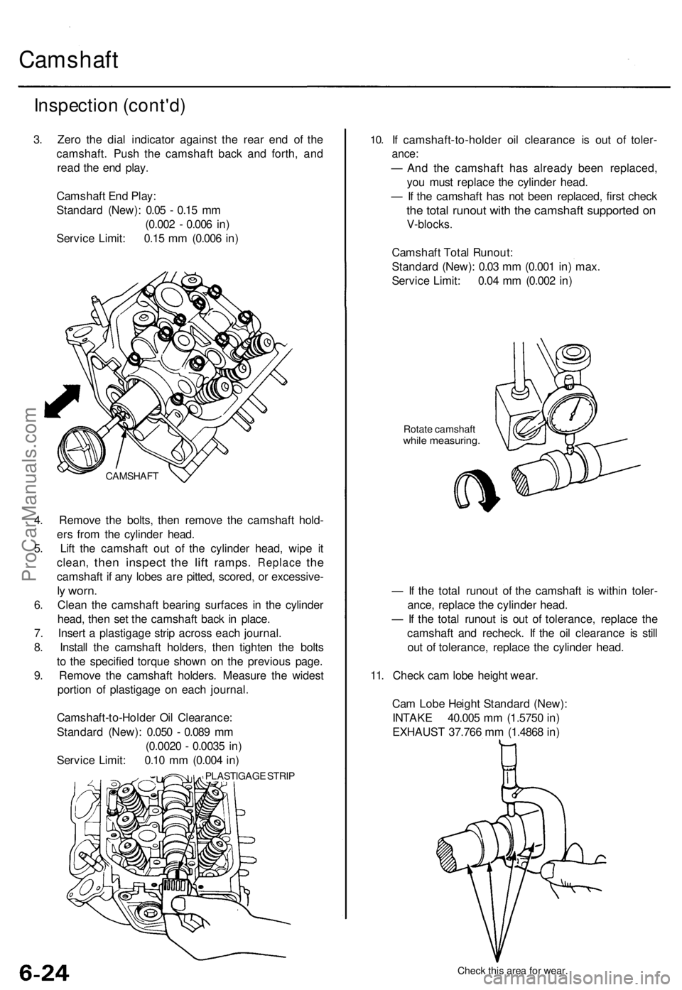
3. Zero the dial indicator against the rear end of the
camshaft. Push the camshaft back and forth, and
read the end play.
Camshaft End Play:
Standard (New): 0.05 - 0.15 mm
(0.002 - 0.006 in)
Service Limit: 0.15 mm (0.006 in)
4. Remove the bolts, then remove the camshaft hold-
ers from the cylinder head.
5. Lift the camshaft out of the cylinder head, wipe it
clean,
then
inspect
the
lift
ramps.
Replace
the
camshaft if any lobes are pitted, scored, or excessive-
ly worn.
6. Clean the camshaft bearing surfaces in the cylinder
head, then set the camshaft back in place.
7. Insert a plastigage strip across each journal.
8. Install the camshaft holders, then tighten the bolts
to the specified torque shown on the previous page.
9. Remove the camshaft holders. Measure the widest
portion of plastigage on each journal.
Camshaft-to-Holder Oil Clearance:
Standard (New): 0.050 - 0.089 mm
(0.0020 - 0.0035 in)
Service Limit: 0.10 mm (0.004 in)
PLASTIGAGE STRIP
10.
If camshaft-to-holder oil clearance is out of toler-
ance:
— And the camshaft has already been replaced,
you must replace the cylinder head.
— If the camshaft has not been replaced, first check
the total runout with the camshaft supported on
V-blocks.
Camshaft Total Runout:
Standard (New): 0.03 mm (0.001 in) max.
Service Limit: 0.04 mm (0.002 in)
Rotate camshaft
while measuring.
— If the total runout of the camshaft is within toler-
ance, replace the cylinder head.
— If the total runout is out of tolerance, replace the
camshaft and recheck. If the oil clearance is still
out of tolerance, replace the cylinder head.
11. Check cam lobe height wear.
Cam Lobe Height Standard (New):
INTAKE 40.005 mm (1.5750 in)
EXHAUST 37.766 mm (1.4868 in)
Check this area for wear.
CAMSHAFTProCarManuals.com
Page 92 of 1771
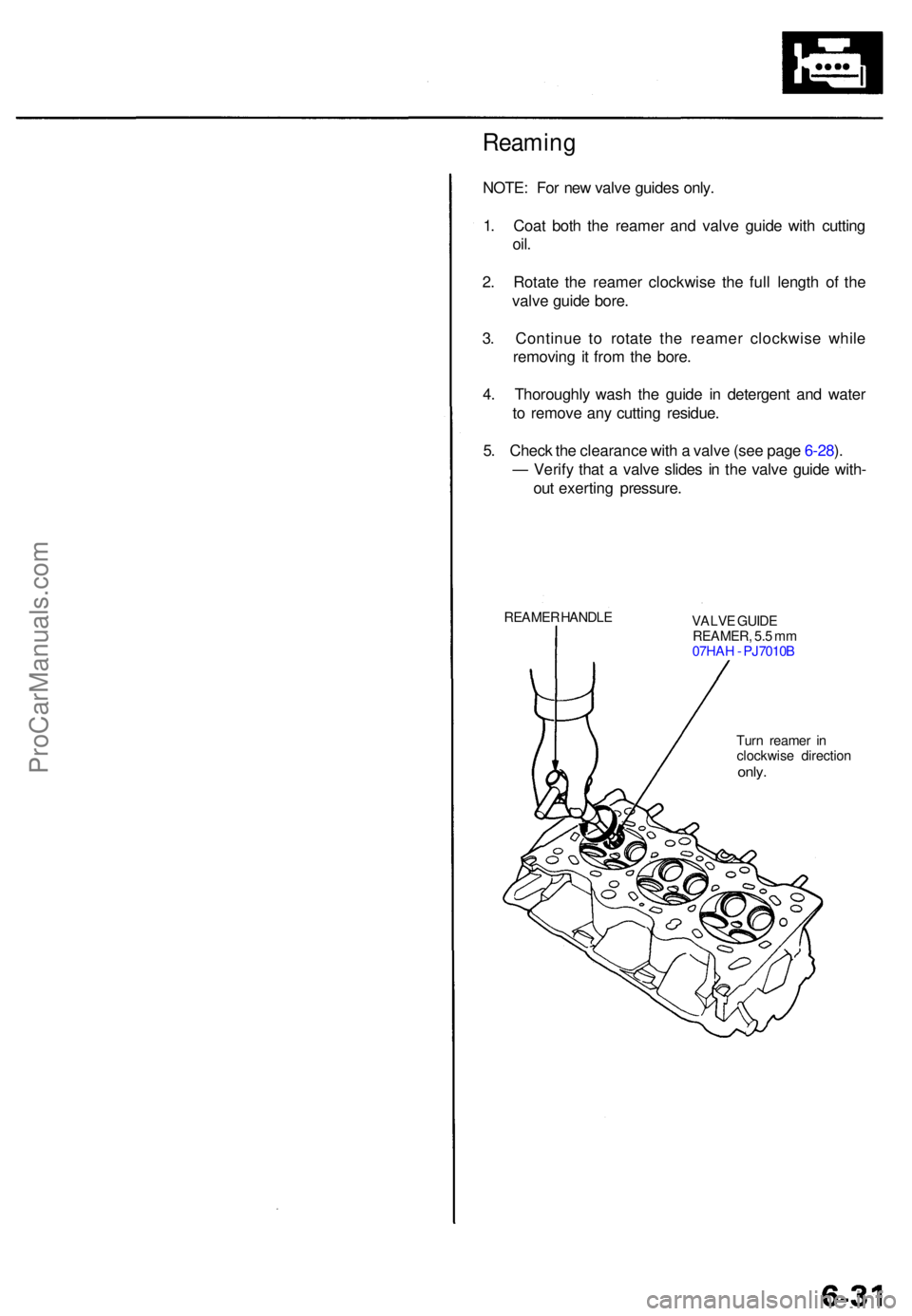
Reaming
NOTE: Fo r ne w valv e guide s only .
1 . Coa t bot h th e reame r an d valv e guid e wit h cuttin g
oil.
2. Rotat e th e reame r clockwis e th e ful l lengt h o f th e
valv e guid e bore .
3 . Continu e t o rotat e th e reame r clockwis e whil e
removin g i t fro m th e bore .
4 . Thoroughl y was h th e guid e i n detergen t an d wate r
t o remov e an y cuttin g residue .
5 . Chec k th e clearanc e wit h a valv e (se e pag e 6-28 ).
— Verif y tha t a valv e slide s i n th e valv e guid e with -
ou t exertin g pressure .
REAMER HANDL E
VALVE GUID E
REAMER , 5. 5 m m
07HA H - PJ7010 B
Tur n reame r i n
clockwis e directio n
only.
ProCarManuals.com
Page 93 of 1771
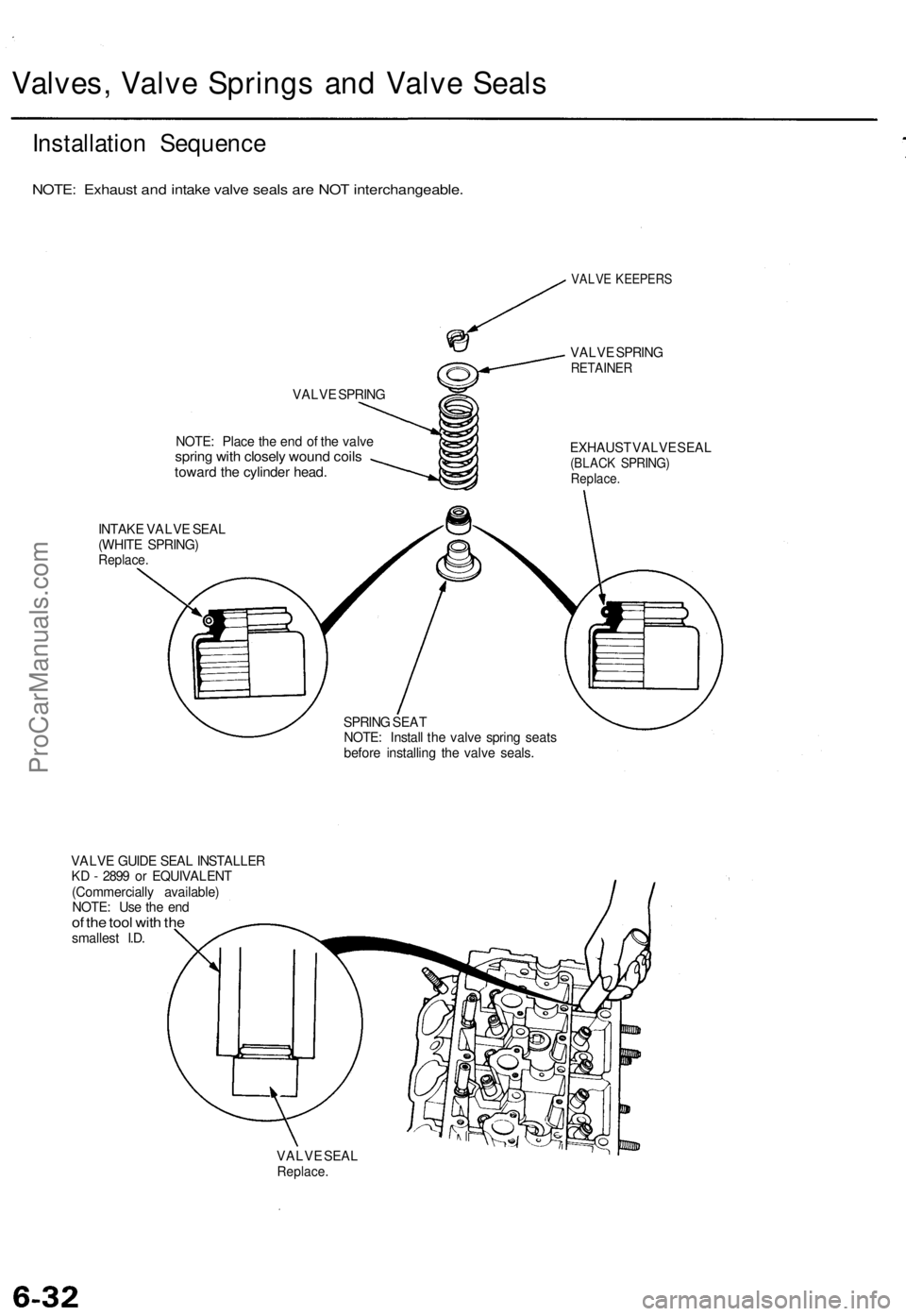
Valves, Valve Springs and Valve Seals
Installation Sequence
NOTE: Exhaust and intake valve seals are NOT interchangeable.
VALVE SPRING
NOTE: Place the end of the valve
spring with closely wound coils
toward the cylinder head.
INTAKE VALVE SEAL
(WHITE SPRING)
Replace.
VALVE KEEPERS
VALVE SPRING
RETAINER
EXHAUST VALVE SEAL
(BLACK SPRING)
Replace.
SPRING SEAT
NOTE: Install the valve spring seats
before installing the valve seals.
VALVE GUIDE SEAL INSTALLER
KD - 2899 or EQUIVALENT
(Commercially available)
NOTE: Use the end
of the tool with the
smallest I.D.
VALVE SEAL
Replace.ProCarManuals.com