stop start ACURA TL 1995 Service Repair Manual
[x] Cancel search | Manufacturer: ACURA, Model Year: 1995, Model line: TL, Model: ACURA TL 1995Pages: 1771, PDF Size: 62.49 MB
Page 198 of 1771
Troubleshooting
How to Read Flowcharts
A flowchart is designed to be used from start to final repair. It's like a map showing you the shortest distance. But beware:
if you go off the "map" anywhere but a "stop" symbol, you can easily get lost.
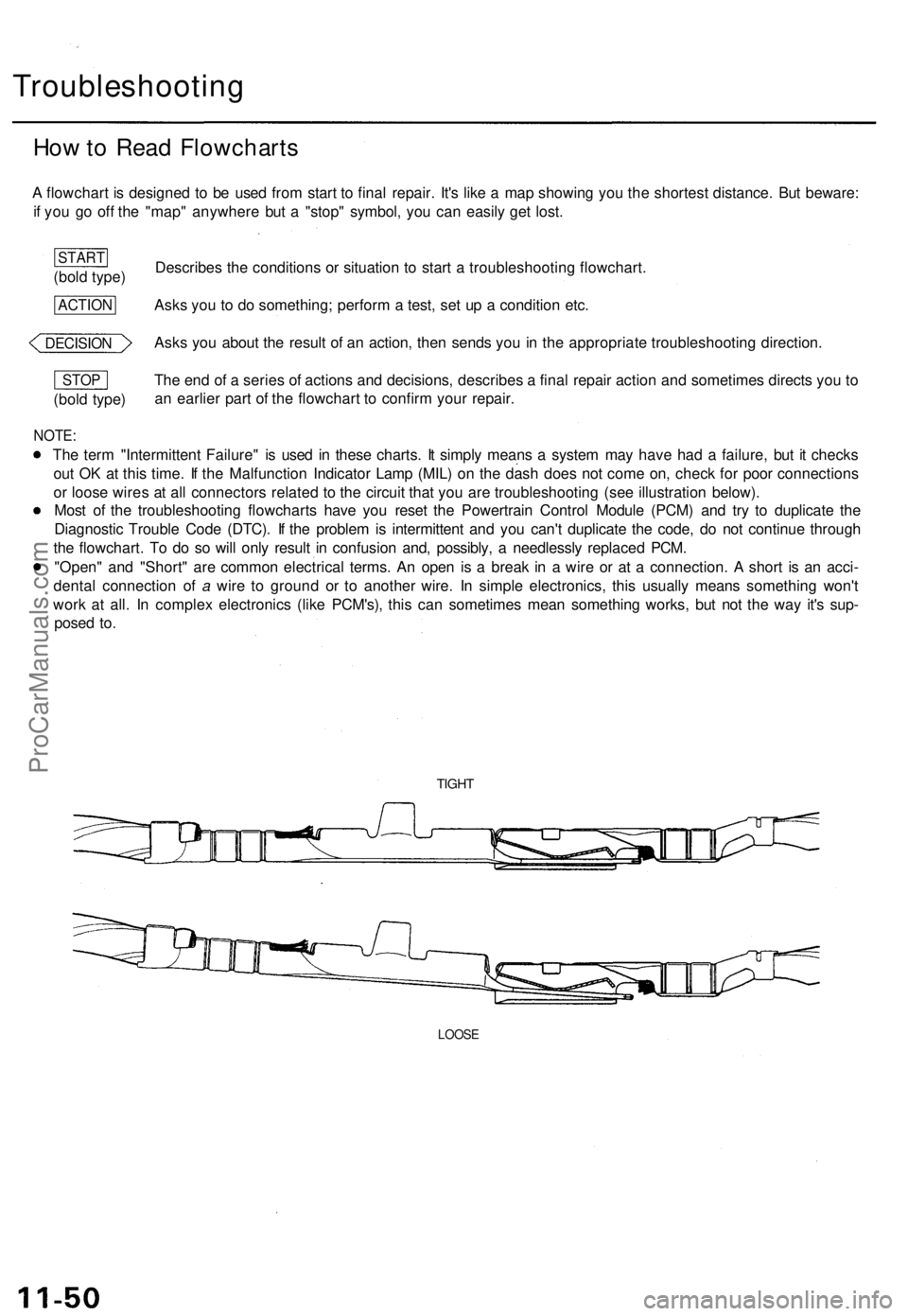
Describes the conditions or situation to start a troubleshooting flowchart.
Asks you to do something; perform a test, set up a condition etc.
Asks you about the result of an action, then sends you in the appropriate troubleshooting direction.
The end of a series of actions and decisions, describes a final repair action and sometimes directs you to
an earlier part of the flowchart to confirm your repair.
NOTE:
The term "Intermittent Failure" is used in these charts. It simply means a system may have had a failure, but it checks
out OK at this time. If the Malfunction Indicator Lamp (MIL) on the dash does not come on, check for poor connections
or loose wires at all connectors related to the circuit that you are troubleshooting (see illustration below).
Most of the troubleshooting flowcharts have you reset the Powertrain Control Module (PCM) and try to duplicate the
Diagnostic Trouble Code (DTC). If the problem is intermittent and you can't duplicate the code, do not continue through
the flowchart. To do so will only result in confusion and, possibly, a needlessly replaced PCM.
"Open" and "Short" are common electrical terms. An open is a break in a wire or at a connection. A short is an acci-
dental connection of a wire to ground or to another wire. In simple electronics, this usually means something won't
work at all. In complex electronics (like PCM's), this can sometimes mean something works, but not the way it's sup-
posed to.
TIGHT
LOOSE
(bold type)
STOP
DECISION
ACTION
(bold type)
STARTProCarManuals.com
Page 258 of 1771
Description
(cont'd)
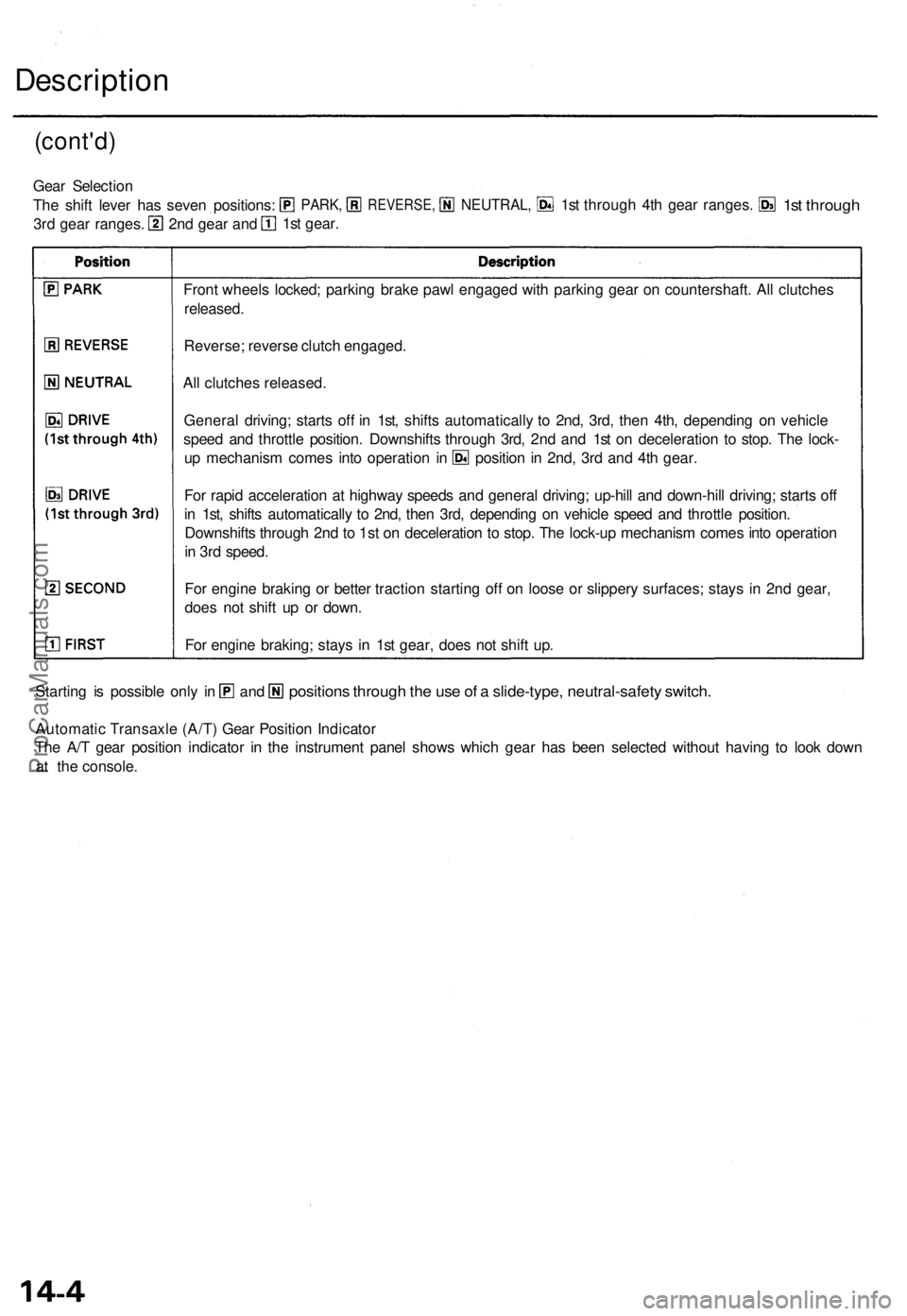
Front wheel s locked ; parkin g brak e paw l engage d wit h parkin g gea r o n countershaft . Al l clutche s
released .
Reverse ; revers e clutc h engaged .
Al l clutche s released .
Automati c Transaxl e (A/T ) Gea r Positio n Indicato r
Th e A/ T gea r positio n indicato r i n th e instrumen t pane l show s whic h gea r ha s bee n selecte d withou t havin g t o loo k dow n
a t the c onsole .
position s throug h th e us e o f a slide-type , neutral-safet y switch .Starting i s possibl e onl y i nan d
Gea r Selectio n
Th e shif t leve r ha s seve n positions :
3r d gea r ranges . 1s
t gear .
2n d gea r an d
PARK ,REVERSE ,NEUTRAL,1st throug h 4t h gea r ranges .1st throug h
For rapi d acceleratio n a t highwa y speed s an d genera l driving ; up-hil l an d down-hil l driving ; start s of f
i n 1st , shift s automaticall y t o 2nd , the n 3rd , dependin g o n vehicl e spee d an d throttl e position .
Downshift s throug h 2n d to
1st o n deceleratio n t o stop . Th e lock-u p mechanis m come s int o operatio n
i n 3r d speed .
Fo r engin e brakin g o r bette r tractio n startin g of f o n loos e o r slipper y surfaces ; stay s i n 2n d gear ,
doe s no t shif t u p o r down .
Fo r engin e braking ; stay s i n 1s t gear , doe s no t shif t up .
Genera
l driving ; start s of f i n 1st , shift s automaticall y t o 2nd , 3rd , the n 4th , dependin g o n vehicl e
spee d an d throttl e position . Downshift s throug h 3rd , 2n d an d 1s t o n deceleratio n t o stop . Th e lock -
u p mechanis m come s int o operatio n i n positio n in 2nd , 3r d an d 4t h gear .
ProCarManuals.com
Page 284 of 1771
Position
(cont'd)
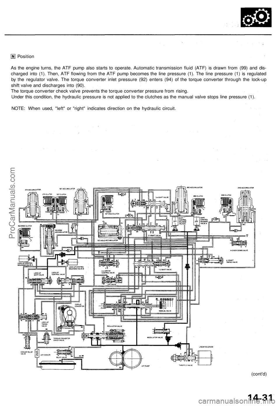
As the engine turns, the ATF pump also starts to operate. Automatic transmission fluid (ATF) is drawn from (99) and dis-
charged into (1). Then, ATF flowing from the ATF pump becomes the line pressure (1). The line pressure (1) is regulated
by the regulator valve. The torque converter inlet pressure (92) enters (94) of the torque converter through the lock-up
shift valve and discharges into (90).
The torque converter check valve prevents the torque converter pressure from rising.
Under this condition, the hydraulic pressure is not applied to the clutches as the manual valve stops line pressure (1).
NOTE: When used, "left" or "right" indicates direction on the hydraulic circuit.ProCarManuals.com
Page 334 of 1771
![ACURA TL 1995 Service Repair Manual
6. Disconnect the transmission sub-harness connector (14P).
7. Start the engine, and run it at 2,000 rpm.
TRANSMISSION SUB-HARNESS
CONNECTOR (14P)
8. Shift to the [HI or [P] position, and measure ACURA TL 1995 Service Repair Manual
6. Disconnect the transmission sub-harness connector (14P).
7. Start the engine, and run it at 2,000 rpm.
TRANSMISSION SUB-HARNESS
CONNECTOR (14P)
8. Shift to the [HI or [P] position, and measure](/img/32/56993/w960_56993-333.png)
6. Disconnect the transmission sub-harness connector (14P).
7. Start the engine, and run it at 2,000 rpm.
TRANSMISSION SUB-HARNESS
CONNECTOR (14P)
8. Shift to the [HI or [P] position, and measure line pressure at fully-opened throttle.
9. Connect battery voltage to the linear solenoid terminals of the transmission sub-harness connector as shown.
10. Measure line pressure at fully-closed throttle.
If line pressure is out of specification, check and repair the probable cause in the table below.
PRESSURE
Line
SHIFT LEVER
POSITION
or
SYMPTOM
No (or
low)
line pressure
PROBABLE CAUSE
Torque converter,
ATF pump, pres-
sure regulator.
torque converter
check valve
FLUID PRESSURE
Standard
520 kPa
(5.3 kgf/cm2, 75 psi)
Fully closed throttle
|
910 kPa
(9.3 kgf/cm2, 130 psi)
Fully opened throttle
Service Limit
500 kPa
(5.1 kgf/cm2, 73 psi)
Fully closed throttle
790 kPa
(8.1 kgf/cm2, 120 psi)
Fully opened throttle
11. Stop the engine, and connect the transmission sub-harness connector (14P).
12. Disconnect the special tool from line pressure inspection hole, and connect the special tool to each inspection hole.
13. Start the engine, and run it at 2,000 rpm.
(cont'd)ProCarManuals.com
Page 508 of 1771
Troubleshooting Precautions
ABS Indicator Light:
The ABS indicator light comes on for three seconds and then goes off when the control unit detects no problem during the
initial diagnosis right after the engine starts. However, the ABS indicator light can stay on for up to 40 seconds when the
control unit starts to check for pump overrun, etc. during the initial diagnosis. The ABS indicator light comes on, and the
ABS control unit memorizes the diagnostic trouble code (DTC) under certain conditions.
• The parking brake is applied for more than 30 seconds while the vehicle is being driven. (DTC 2-1)
• The transmission downshifted excessively. (DTC 4-1, 4-2)
• The vehicle loses traction, and the front wheels spin for more than one minute when starting from a stuck condition on
a muddy, snowy, or sandy road. (DTC 4-8)
• Tire adhesion is lost due to excessive cornering speed. (DTC 5, 5-4, 5-8)
• The vehicle is driven on an extremely rough road. (DTC 8-1)
• The vehicle is interfered by strong radio waves (noise), for example, illegal radio, etc. (DTC 8-2)
NOTE: If there is any trouble in the system, the ABS indicator light comes on during driving.
Diagnostic Trouble Code (DTC):
• When the control unit detects a problem and the ABS indicator light comes on, the control unit memorizes the DTC.
• The control unit has three memory registers. When a problem occurs, the control unit stores the DTC in the first memory
register. If another problem occurs, or the same problem occurs again, the control unit moves the first DTC to the next
memory register, and stores the second DTC in the first register. If there's a third problem occurrence, the two existing
DTCs are moved up one register, and the third DTC is stored in the first register. If problems continue to occur, the oldest
problem is moved out of the last register and lost, and the most recent problem is stored in the first register. When the
same problem occurs three times, the same DTC is stored in all memory registers. (Refer to the Symptom-to-System
Chart for diagnostic period.)
• The most recent DTC is indicated first, and the oldest DTC is indicated last.
• The DTCs are erased from the control unit when the ABS control unit +B2 power supply or connector is disconnected.
• The control unit's memory can be erased by disconnecting the ABS B2 fuse for more than three seconds.
Self-diagnosis:
• There are three self-diagnosises described below.
Initial diagnosis: Performed right after the engine starts until the ABS indicator light goes off.
Regular diagnosis: Continuously performed (under some conditions) after the ABS indicator light goes off until the
engine stops.
Individual part/system diagnosis: Diagnosis about a specific part/system under its operating conditions.
• The CPU (central processing unit) controls the following when it detects a problem during self-diagnosis:
Turns the ABS indicator light ON.
Turns the front and rear fail-safe relays off.
Stops the ABS control.
Stops the ABS pump. (The pump may work under some conditions.)
After the DTC is stored in the control unit, the CPU stops self-diagnosis.ProCarManuals.com
Page 522 of 1771
Troubleshooting Precautions
ABS Indicator Light
1. If the system is OK, the ABS indicator light goes off two seconds after turning the ignition switch ON (II) without start-
ing the engine. After starting the engine, the ABS indicator light comes on again and goes off after two seconds. This
occurs because the ABS control unit is activated by the IG2 power source.
2. The ABS indicator light comes on when the ABS control unit detects a problem in the system. However, even though
the system is normal, the ABS indicator light comes on, too, under the following conditions. To determine the actual
cause of problem, question the customer about the problem, talking the following conditions into consideration.
Only drive wheels rotate
One wheel stuck of drive wheels
Vehicle spin
ABS operate condition continue for long time
Signal disturbance
3. When a problem is detected and the ABS indicator light comes on, there are cases when the indicator light stays on
until the ignition switch is turned OFF, and cases when the indicator light goes off automatically when the system
returns normal. For the DTC 61 and 62, the indicator light goes off automatically when the system returns normal. For
all other codes, the indicator light stays on until the ignition switch is turned OFF.
4. For DTCs 12, 14, 16, 18, 21, 22, 23, 24, 51, 52 and 53, the indicator light goes off when the vehicle is driven again and
the signals are OK after the ignition switch is turned from OFF to ON (II). However, if the DTC is erased, the CPU is
reset and the indicator light goes off right after the engine is started if the signals are OK.
Diagnostic Trouble Code (DTC)
1. The DTC is not memorized if the CPU cannot be activated or the CPU fails and the indicator light comes on.
2. The memory can hold any number of DTCs. However, when the same DTC is detected more than once, the later one
is written over the old one. Therefore, when the same problem is detected repeatedly, it is memorized as one DTC.
3. The DTCs are indicated in the order of ascending number, not in the order they occur.
4. The DTCs are memorized in the EEPROM (non-volatile memory). Therefore, the memorized DTCs cannot be canceled
by disconnecting the battery. Perform the specified procedures to erase the DTCs.
Self-diagnosis
1. The
self-diagnosis
can be
classified
into
two
categories.
• Initial diagnosis: Performed right after the engine starts and until the ABS indicator light goes off.
• Regular diagnosis: Performed right after the initial diagnosis until the ignition switch is turned OFF.
2. When a problem is detected by self-diagnosis, the system
• Turns the ABS indicator light ON
• Memorizes the DTC
• Turns the fail-safe relay OFF
• Stops ABS controlProCarManuals.com
Page 876 of 1771
How to Read Flowcharts
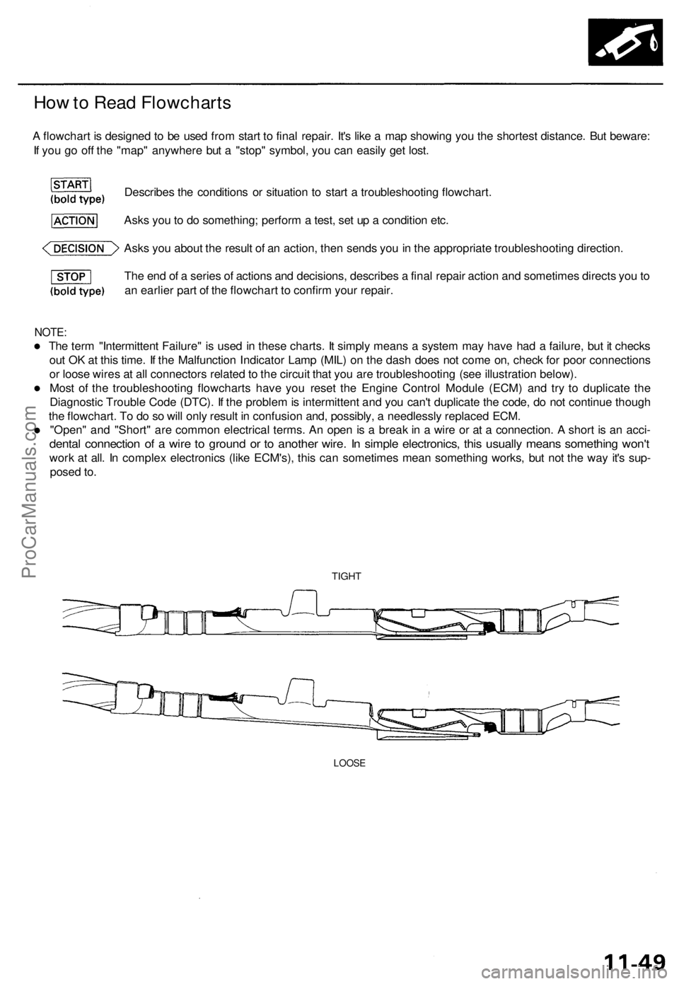
A flowchart is designed to be used from start to final repair. It's like a map showing you the shortest distance. But beware:
If you go off the "map" anywhere but a "stop" symbol, you can easily get lost.
Describes the conditions or situation to start a troubleshooting flowchart.
Asks you to do something; perform a test, set up a condition etc.
Asks you about the result of an action, then sends you in the appropriate troubleshooting direction.
The end of a series of actions and decisions, describes a final repair action and sometimes directs you to
an earlier part of the flowchart to confirm your repair.
NOTE:
The term "Intermittent Failure" is used in these charts. It simply means a system may have had a failure, but it checks
out OK at this time. If the Malfunction Indicator Lamp (MIL) on the dash does not come on, check for poor connections
or loose wires at all connectors related to the circuit that you are troubleshooting (see illustration below).
Most of the troubleshooting flowcharts have you reset the Engine Control Module (ECM) and try to duplicate the
Diagnostic Trouble Code (DTC). If the problem is intermittent and you can't duplicate the code, do not continue though
the flowchart. To do so will only result in confusion and, possibly, a needlessly replaced ECM.
"Open" and "Short" are common electrical terms. An open is a break in a wire or at a connection. A short is an acci-
dental connection of a wire to ground or to another wire. In simple electronics, this usually means something won't
work at all. In complex electronics (like ECM's), this can sometimes mean something works, but not the way it's sup-
posed to.
TIGHT
LOOSEProCarManuals.com
Page 878 of 1771
4. A/ C Compresso r Clutc h Rela y
When th e EC M receive s a deman d fo r coolin g fro m th e ai r conditionin g system , i t delay s th e compresso r fro m bein g
energized , an d enriche s th e mixtur e to assur e smoot h transitio n to th e A/ C mode .
5 . Evaporativ e Emissio n (EVAP ) Purg e Contro l Solenoi d Valv e
Whe n th e engin e coolan t temperatur e i s belo w 167° F (75°C ) ('9 7 - 9 8 models : 158° F (70°C) , th e EC M control s th e
EVA P purg e contro l solenoi d valv e whic h cut s vacuu m to th e EVA P purg e contro l caniste r diaphragm .
6 . Intak e Ai r Bypas s (IAB ) Contro l Solenoi d Valv e
Whe n th e engin e spee d i s belo w 4,80 0 rpm , th e IA B contro l solenoi d valv e i s activate d b y a signa l fro m th e ECM ,
intak e ai r flow s throug h th e smalle r chamber , the n hig h torqu e i s delivered. At speed s highe r tha n 4,80 0 rpm , th e
solenoi d valv e i s deactivate d b y th e ECM , an d intak e ai r flow s throug h th e large r chambe r i n orde r t o reduc e th e
resistanc e in airflow .
7 . Exhaus t Ga s Recirculatio n (EGR ) Contro l Solenoi d Valv e
Whe n th e EG R is require d fo r contro l o f oxide s o f nitroge n (NOx ) emissions , th e EC M control s th e EG R contro l
solenoi d valv e whic h supplie s regulate d vacuu m to th e EG R valve .
8 . Alternato r Contro l
Th e syste m control s th e voltag e generate d a t th e alternato r i n accordanc e wit h th e electrica l loa d an d drivin g mode ,
whic h reduce s th e engin e loa d to improv e th e fue l economy .
ECM Fail-safe/Back-u p Function s
1. Fail-saf e Functio n
Whe n a n abnormalit y occur s in a signa l fro m a sensor , th e EC M ignore s tha t signa l an d assume s a pre-programme d
valu e fo r tha t senso r tha t allow s th e engin e to continu e to run .
2 . Back-u p Functio n
Whe n a n abnormalit y occur s in th e EC M itself , th e fue l injector s ar e controlle d b y a back-u p circui t independen t o f th e
syste m in orde r t o permi t minima l driving .
3 . Self-diagnosi s Functio n [Malfunctio n Indicato r Lam p (MIL) ]
Whe n a n abnormalit y occur s i n a signa l fro m a sensor , th e EC M supplie s groun d fo r th e MI L an d store s th e DT C in
erasable memory . Whe n th e ignitio n i s initiall y turne d on , th e EC M supplie s ground for th e MI L fo r tw o second s t o
chec k th e MI L bul b condition .
4 . Tw o Tri p Detectio n Metho d ('9 5 - 9 6 models )
T o preven t fals e indications , th e Tw o Tri p Detectio n Metho d is use d fo r th e MA F sensor , H02S , fue l metering-related ,
idl e contro l system , EC T sensor , an d EG R syste m self-diagnosti c functions . Whe n a n abnormalit y occurs , th e EC M
store s i t i n it s memory . Whe n th e sam e abnormalit y recur s afte r th e ignitio n switc h i s turne d OF F an d O N (II ) again ,
th e EC M inform s th e drive r b y lightin g th e MIL .
However ,
to eas e troubleshooting , thi s functio n is cancelle d when you shor t the servic e check connector . The MI L will
the n blin k immediatel y whe n a n abnormalit y occurs .
5 . Tw o (o r Three ) Drivin g Cycl e Detectio n Metho d ('9 5 - 9 6 models )
A "Drivin g Cycle " consist s o f startin g th e engine , beginnin g close d loo p operation , an d stoppin g th e engine . I f misfir -
in g tha t increase s emission s o r EVA P contro l syste m malfunctio n i s detecte d i n tw o consecutiv e drivin g cycles , o r
TW C deterioratio n is detecte d in thre e consecutiv e drivin g cycles , th e EC M turn s th e MI L on .
However , t o eas e troubleshooting , thi s functio n is cancelle d whe n yo u shor t th e servic e chec k connector . Th e MI L wil l
the n blin k immediatel y whe n a n abnormalit y occurs .
6 . Tw o Drivin g Cycl e Detectio n Metho d ('9 7 - 9 8 models )
T o preven t fals e indications , th e "tw o drivin g cycl e detectio n method " i s use d fo r th e H02S , fue l metering-related ,
idl e contro l system , EC T sensor , EG R system , TW C an d EVA P contro l syste m an d othe r self-diagnosti c functions .
Whe n a n abnormalit y occurs , th e EC M store s i t i n it s memory . Whe n th e sam e abnormalit y recur s afte r switc h i s
turne d OF F an d O N (II ) again , th e EC M inform s th e drive r b y turnin g o n th e MIL .
ProCarManuals.com
Page 920 of 1771
Intake Ai r Syste m
Throttl e Bod y
Descriptio n
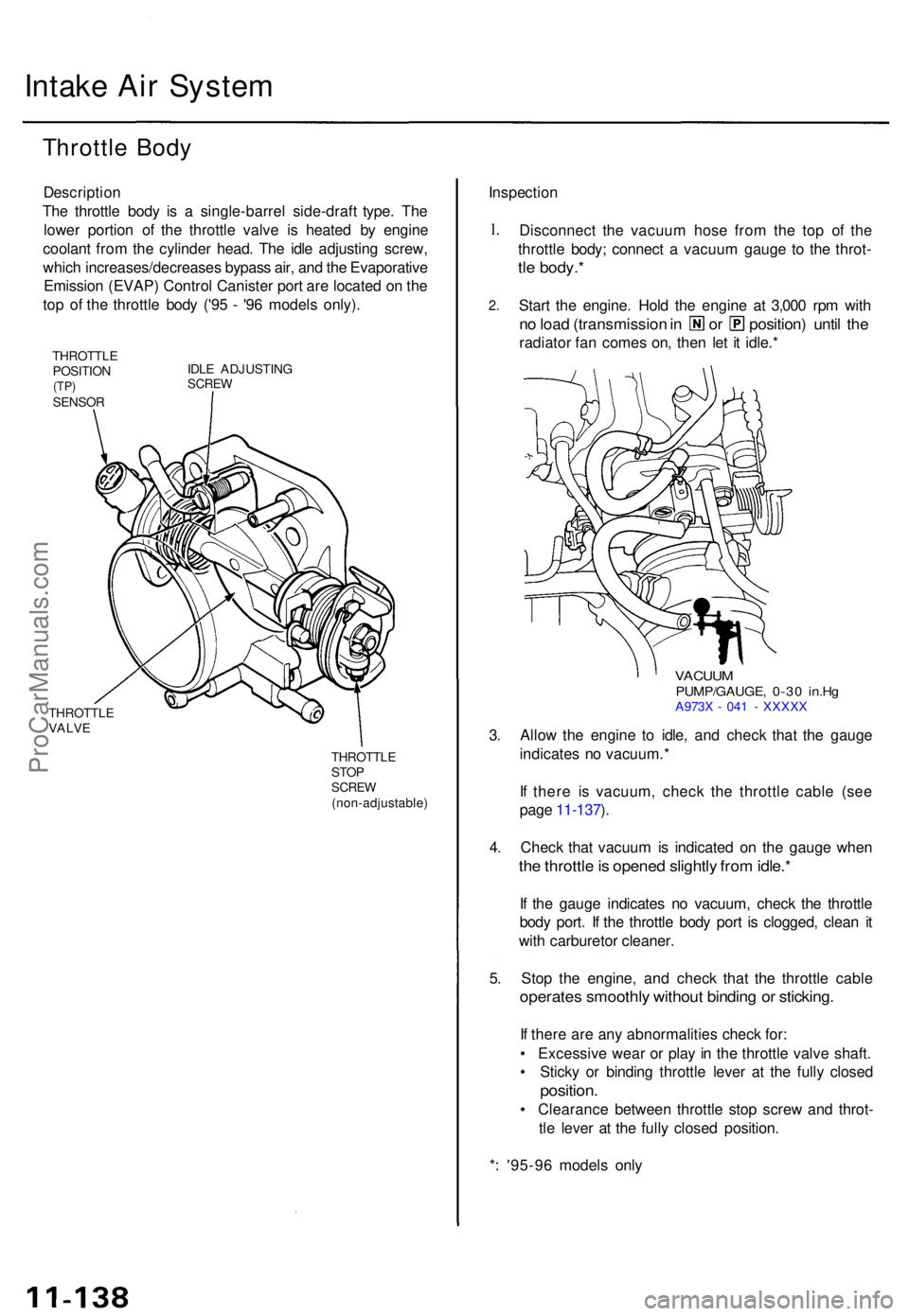
The throttl e bod y i s a single-barre l side-draf t type . Th e
lowe r portio n o f th e throttl e valv e i s heate d b y engin e
coolan t fro m th e cylinde r head . Th e idl e adjustin g screw ,
whic h increases/decrease s bypas s air , an d th e Evaporativ e
Emissio n (EVAP ) Contro l Caniste r por t ar e locate d o n th e
to p o f th e throttl e bod y ('9 5 - '9 6 model s only) .
THROTTL E
POSITIO N
(TP)SENSO R IDL
E ADJUSTIN G
SCREW
THROTTL EVALVE
THROTTL ESTOPSCRE W(non-adjustable )
Inspection
1.
2 .
Disconnec t th e vacuu m hos e fro m th e to p of the
throttl e body ; connec t a vacuu m gaug e t o th e throt -
tle body. *
Start th e engine . Hol d th e engin e a t 3,00 0 rp m wit h
no loa d (transmissio n in o r position ) unti l th e
radiato r fa n come s on , the n le t i t idle. *
VACUU MPUMP/GAUGE , 0-3 0 in.H gA973 X - 04 1 - XXXX X
3. Allo w th e engin e t o idle , an d chec k tha t th e gaug e
indicate s n o vacuum. *
I f ther e i s vacuum , chec k th e throttl e cabl e (se e
pag e 11-137 ).
4 . Chec k tha t vacuu m is indicate d o n th e gaug e whe n
the throttl e is opene d slightl y fro m idle. *
If th e gaug e indicate s n o vacuum , chec k th e throttl e
bod y port . I f th e throttl e bod y por t i s clogged , clea n i t
wit h carbureto r cleaner .
5 . Sto p th e engine , an d chec k tha t th e throttl e cabl e
operates smoothly withou t bindin g o r sticking .
If ther e ar e an y abnormalitie s chec k for :
• Excessiv e wea r o r pla y i n th e throttl e valv e shaft .
• Stick y o r bindin g throttl e leve r a t th e full y close d
position .
• Clearanc e betwee n throttl e sto p scre w an d throt -
tl e leve r a t th e full y close d position .
* : '95-9 6 model s onl y
ProCarManuals.com
Page 937 of 1771
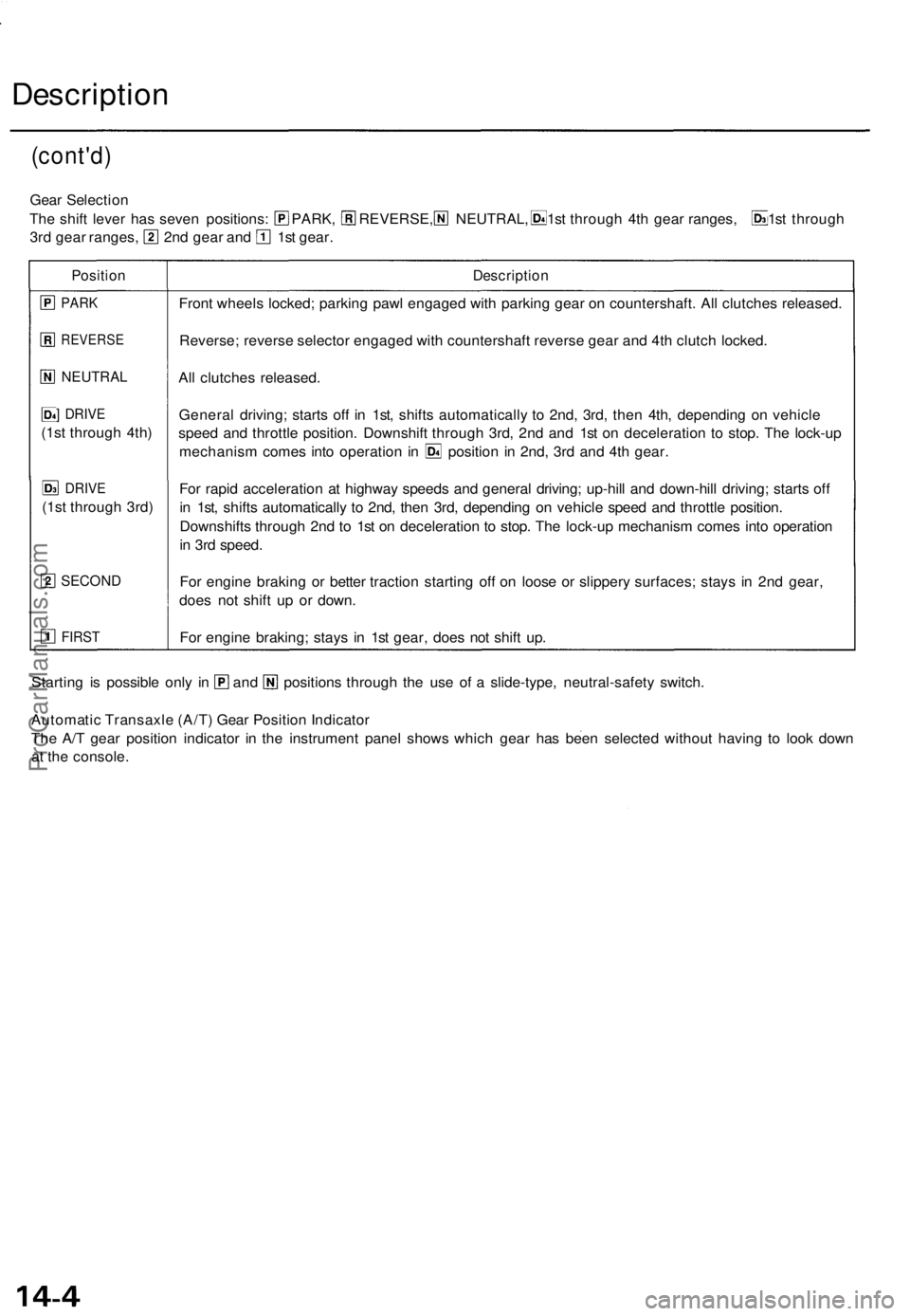
Description
(cont'd)
Gear Selectio n
The shif t leve r ha s seve n positions : PARK , REVERSE, NEUTRAL , 1st throug h 4t h gea r ranges , 1s t throug h
3rd gea r ranges , 2n d gea r an d 1s t gear .
Positio nDescriptio n
PARK
REVERS E
NEUTRAL
] DRIV E
(1st throug h 4th )
DRIV E
(1st throug h 3rd )
SECON D
FIRST
Front wheel s locked ; parkin g paw l engage d wit h parkin g gea r o n countershaft . Al l clutche s released .
Reverse ; revers e selecto r engage d wit h countershaf t revers e gea r an d 4t h clutc h locked .
Al l clutche s released .
Genera l driving ; start s of f i n 1st , shift s automaticall y t o 2nd , 3rd , the n 4th , dependin g o n vehicl e
spee d an d throttl e position . Downshif t throug h 3rd , 2n d an d 1s t o n deceleratio n t o stop . Th e lock-u p
mechanis m come s int o operatio n i n positio n i n 2nd , 3r d an d 4t h gear .
Fo r rapi d acceleratio n a t highwa y speed s an d genera l driving ; up-hil l an d down-hil l driving ; start s of f
i n 1st , shift s automaticall y t o 2nd , the n 3rd , dependin g o n vehicl e spee d an d throttl e position .
Downshift s throug h 2n d t o 1s t o n deceleratio n t o stop . Th e lock-u p mechanis m come s int o operatio n
i n 3r d speed .
Fo r engin e brakin g o r bette r tractio n startin g of f o n loos e o r slipper y surfaces ; stay s i n 2n d gear ,
doe s no t shif t u p o r down .
Fo r engin e braking ; stay s i n 1s t gear , doe s no t shif t up .
Startin g i s possibl e onl y i n an d position s throug h th e us e o f a slide-type , neutral-safet y switch .
Automati c Transaxl e (A/T ) Gea r Positio n Indicato r
Th e A/ T gea r positio n indicato r i n th e instrumen t pane l show s whic h gea r ha s bee n selecte d withou t havin g t o loo k dow n
a t th e console .
ProCarManuals.com