timing belt ACURA TL 1995 Service Repair Manual
[x] Cancel search | Manufacturer: ACURA, Model Year: 1995, Model line: TL, Model: ACURA TL 1995Pages: 1771, PDF Size: 62.49 MB
Page 61 of 1771
Timing Bel t
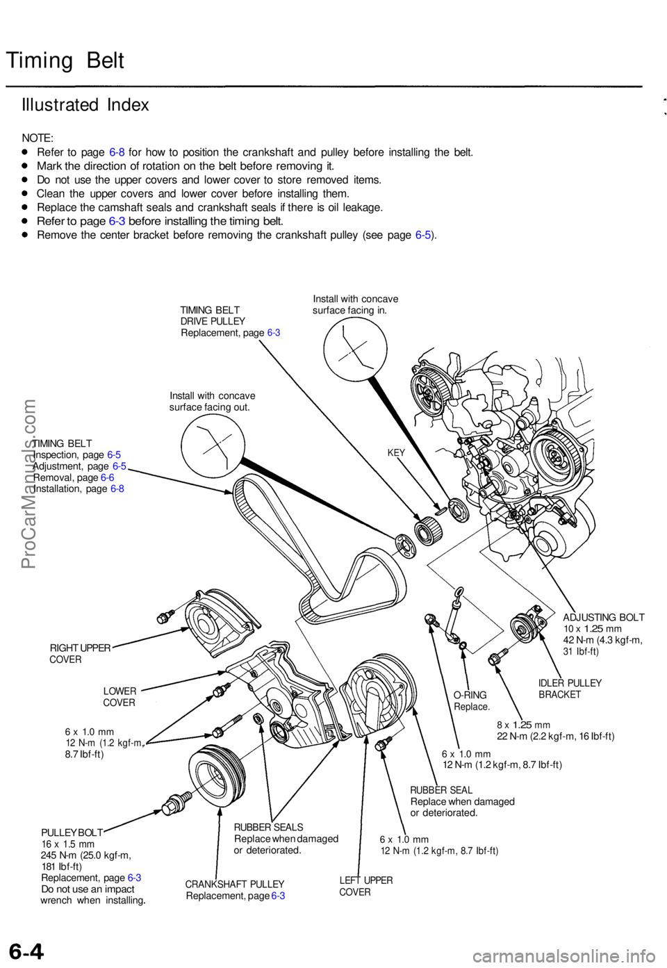
Illustrate d Inde x
NOTE :
Refe r t o pag e 6- 8 fo r ho w to positio n th e crankshaft and pulle y befor e installin g th e belt .
Mark th e directio n o f rotatio n o n th e bel t befor e removin g it .
Do no t us e th e uppe r cover s an d lowe r cove r t o stor e remove d items .
Clea n th e uppe r cover s an d lowe r cove r befor e installin g them .
Replac e th e camshaf t seal s an d crankshaf t seal s i f ther e is oi l leakage .
Refer t o pag e 6- 3 befor e installin g th e timin g belt .
Remov e th e cente r bracke t befor e removin g th e crankshaf t pulle y (se e pag e 6-5 ).
TIMIN G BEL TDRIV E PULLE YReplacement , pag e
Instal l wit h concav e
surfac e facin g out . Instal
l wit h concav e
surfac e facin g in .6-3
TIMIN G BEL T
Inspection , pag e 6- 5
Adjustment , pag e 6-5
Removal , pag e 6- 6
Installation , pag e 6- 8
RIGH T UPPE R
COVE R
6 x 1. 0 m m12 N- m (1. 2 kgf-m ,8.7 Ibf-ft )
PULLE Y BOL T
16 x 1. 5 m m245 N- m (25. 0 kgf-m ,
18 1 Ibf-ft )
Replacement , pag e 6- 3
Do no t us e a n impac twrench whe n installin g ADJUSTIN
G BOL T
10 x 1.2 5 mm42 N- m (4. 3 kgf-m ,31 Ibf-ft )
IDLER PULLE YBRACKE T
8 x 1.2 5 mm22 N- m (2. 2 kgf-m , 1 6 Ibf-ft )
6 x 1. 0 m m12 N- m (1. 2 kgf-m , 8. 7 Ibf-ft )
RUBBE R SEA LReplac e whe n damage d
o r deteriorated .
6 x 1. 0 m m12 N- m (1. 2 kgf-m , 8. 7 Ibf-ft )
CRANKSHAF T PULLE YReplacement , pag e 6- 3
LEF T UPPE RCOVER
RUBBE R SEAL SReplac e whe n damage d
o r deteriorated .
O-RINGReplace .
LOWERCOVER
KEY
ProCarManuals.com
Page 63 of 1771
Timing Bel t
Remova l
NOTE:
Replac e th e timin g bel t a t 105,00 0 mile s (168,00 0 km )
accordin g t o th e maintenanc e schedul e (norma l con -
ditions/sever e conditions) .
I f th e vehicl e is regularl y drive n i n on e o r mor e o f th e
followin g conditions , replac e th e timin g bel t a t 60,00 0
mile s (U.S.A. ) 100,00 0 k m (Canada) .
I n ver y hig h temperature s (ove r 110°F , 43°C )
I n ver y lo w temperature s (unde r -20°F , -29°C )
Tur n th e crankshaf t pulle y s o th e No . 1 pisto n i s a t
to p dea d cente r (TDC ) befor e removin g th e bel t (se e
pag e 6-8 ).
Inspec t th e wate r pum p befor e installin g th e timin g
bel t (se e pag e 10-10 ).
1 . Mak e sur e yo u hav e th e anti-thef t cod e fo r th e radio ,
the n writ e dow n th e frequencie s fo r th e radio' s prese t
buttons .
2. Disconnec t th e negativ e termina l fro m th e battery .
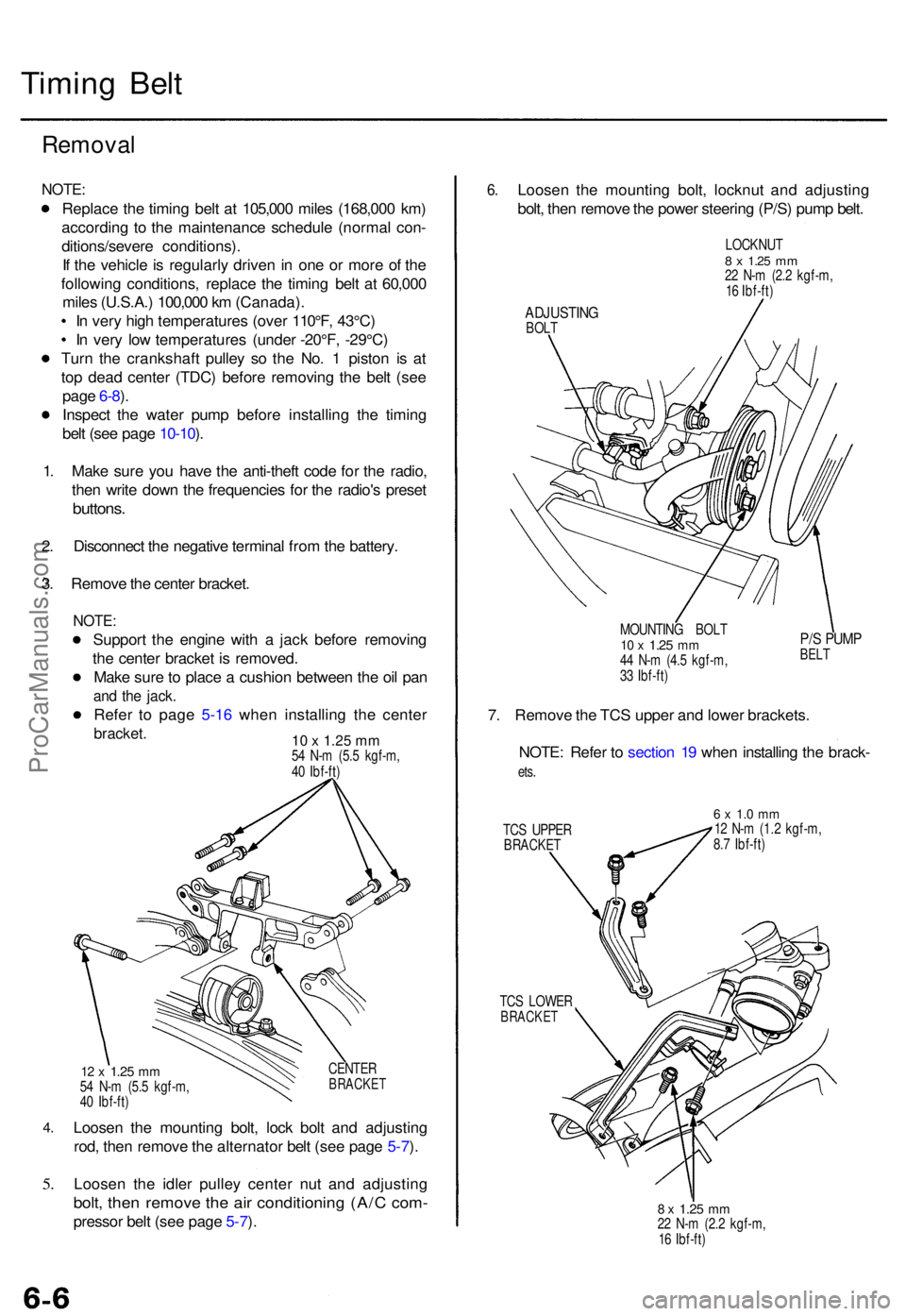
3 . Remov e th e cente r bracket .
NOTE:
Suppor t th e engin e wit h a jac k befor e removin g
th e cente r bracke t i s removed .
Mak e sur e to plac e a cushio n betwee n th e oi l pa n
and th e jack .
Refer t o pag e 5-1 6 whe n installin g th e cente r
bracket. 10 x 1.25 mm54 N- m (5. 5 kgf-m ,
4 0 Ibf-ft )
4.
5.
CENTE RBRACKE T12 x 1.2 5 mm54 N- m (5. 5 kgf-m ,
4 0 Ibf-ft )
Loose n th e mountin g bolt , loc k bol t an d adjustin g
rod , the n remov e th e alternato r bel t (se e pag e 5-7 ).
Loose n th e idle r pulle y cente r nu t an d adjustin g
bolt, the n remov e th e ai r conditionin g (A/ C com -
presso r bel t (se e pag e 5-7 ).
6 .Loose n th e mountin g bolt , locknu t an d adjustin g
bolt , the n remov e th e powe r steerin g (P/S ) pum p belt .
LOCKNU T8 x 1.2 5 mm22 N- m (2. 2 kgf-m ,
1 6 Ibf-ft )
ADJUSTIN GBOLT
MOUNTING BOL T
10 x 1.2 5 mm44 N- m (4. 5 kgf-m ,
3 3 Ibf-ft )
P/S PUM PBELT
7. Remov e th e TC S uppe r an d lowe r brackets .
NOTE : Refe r t o sectio n 1 9 whe n installin g th e brack -
ets.
TC S UPPE RBRACKE T
6 x 1. 0 m m12 N- m (1. 2 kgf-m ,
8. 7 Ibf-ft )
TC S LOWE R
BRACKE T
8 x 1.2 5 mm22 N- m (2. 2 kgf-m ,
1 6 Ibf-ft )
ProCarManuals.com
Page 65 of 1771
Timing Belt
Removal (cont'd)
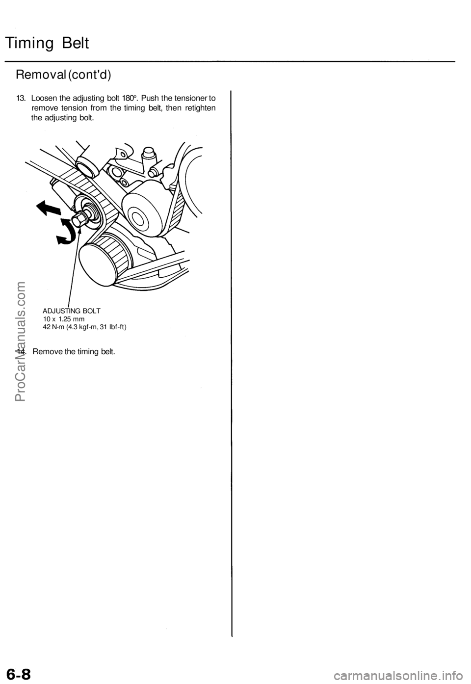
13. Loosen the adjusting bolt 180°. Push the tensioner to
remove tension from the timing belt, then retighten
the adjusting bolt.
ADJUSTING BOLT
10 x
1.25
mm
42 N-m (4.3 kgf-m, 31 Ibf-ft)
14. Remove the timing belt.ProCarManuals.com
Page 68 of 1771
Timing Bel t
Installatio n (cont'd )
9. Adjus t th e timin g bel t tensio n (se e pag e 6-5 ).
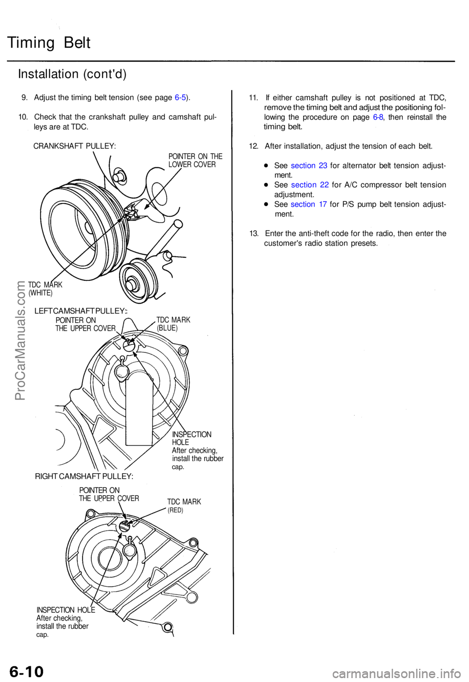
10 . Chec k tha t th e crankshaf t pulle y an d camshaf t pul -
ley s ar e a t TDC .
CRANKSHAF T PULLEY :
TDC MAR K
(WHITE )
LEFT CAMSHAF T PULLEY :
POINTER O NTH E UPPE R COVE R
RIGHT CAMSHAF T PULLEY :
POINTER O NTH E UPPE R COVE R POINTE
R O N TH E
LOWE R COVE R
TD C MAR K
(BLUE )
INSPECTIO NHOLEAfter checking ,install th e rubbe rcap.
TDC MAR K(RED)
INSPECTIO N HOL EAfter checking ,install th e rubbe rcap.
11. I f eithe r camshaf t pulle y i s no t positione d a t TDC ,
remov e th e timin g bel t an d adjus t th e positionin g fol -
lowin g th e procedur e o n pag e 6-8 , the n reinstal l th e
timin g belt .
12. Afte r installation , adjus t th e tensio n o f eac h belt .
Se e sectio n 2 3 fo r alternato r bel t tensio n adjust -
ment .
Se e sectio n 2 2 fo r A/ C compresso r bel t tensio n
adjustment .
Se e sectio n 1 7 fo r P/ S pum p bel t tensio n adjust -
ment .
13 . Ente r th e anti-theft code fo r th e radio , the n ente r th e
customer' s radi o statio n presets .
ProCarManuals.com
Page 116 of 1771
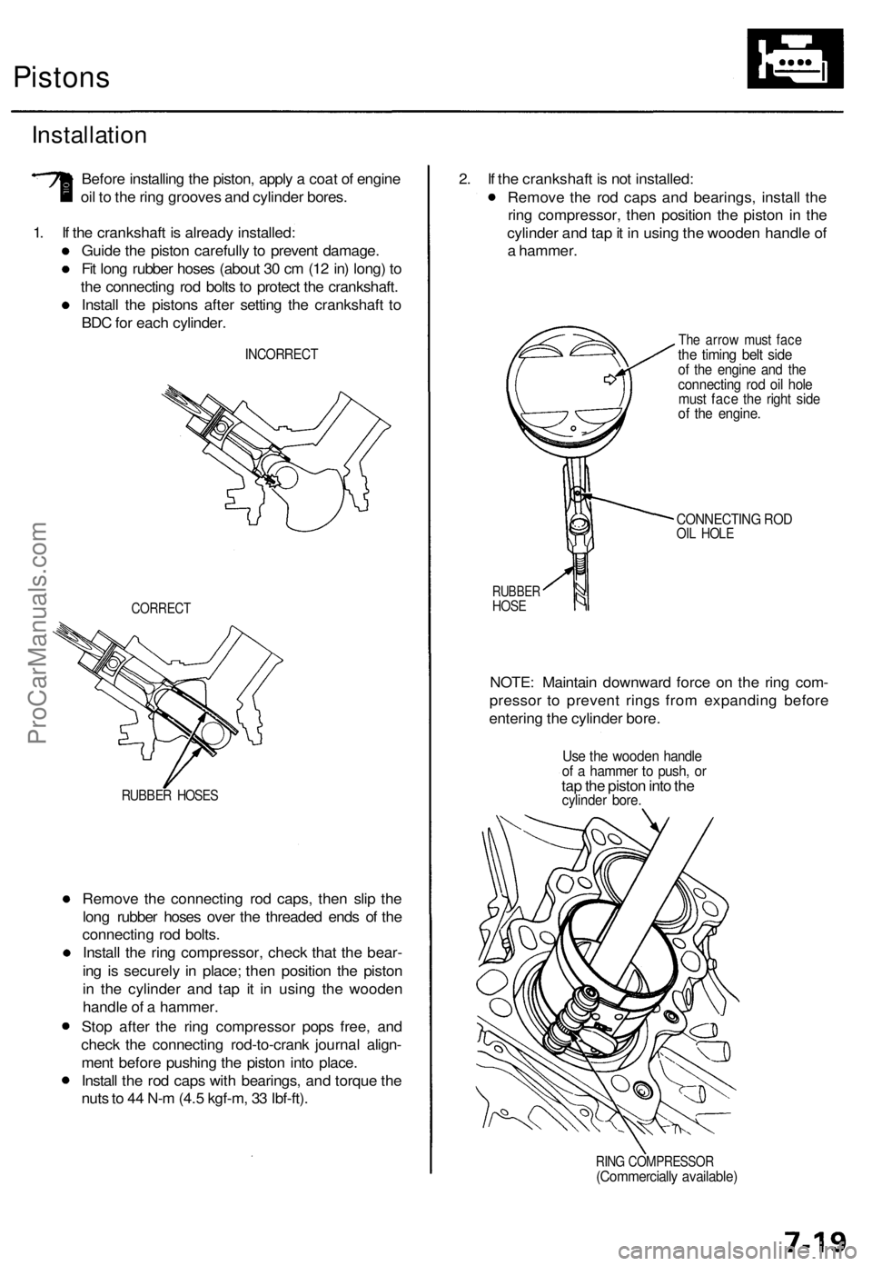
Pistons
Installation
Before installing the piston, apply a coat of engine
oil to the ring grooves and cylinder bores.
1. If the crankshaft is already installed:
Guide the piston carefully to prevent damage.
Fit long rubber hoses (about 30 cm (12 in) long) to
the connecting rod bolts to protect the crankshaft.
Install the pistons after setting the crankshaft to
BDC for each cylinder.
INCORRECT
CORRECT
RUBBER HOSES
Remove the connecting rod caps, then slip the
long rubber hoses over the threaded ends of the
connecting rod bolts.
Install the ring compressor, check that the bear-
ing is securely in place; then position the piston
in the cylinder and tap it in using the wooden
handle of a hammer.
Stop after the ring compressor pops free, and
check the connecting rod-to-crank journal align-
ment before pushing the piston into place.
Install the rod caps with bearings, and torque the
nuts to 44 N-m (4.5 kgf-m, 33 Ibf-ft).
2. If the crankshaft is not installed:
Remove the rod caps and bearings, install the
ring compressor, then position the piston in the
cylinder and tap it in using the wooden handle of
a hammer.
The arrow must face
the timing belt side
of the engine and the
connecting rod oil hole
must face the right side
of the engine.
CONNECTING ROD
OIL HOLE
RUBBER
HOSE
NOTE: Maintain downward force on the ring com-
pressor to prevent rings from expanding before
entering the cylinder bore.
Use the wooden handle
of a hammer to push, or
tap the piston into the
cylinder bore.
RING COMPRESSOR
(Commercially available)ProCarManuals.com
Page 742 of 1771
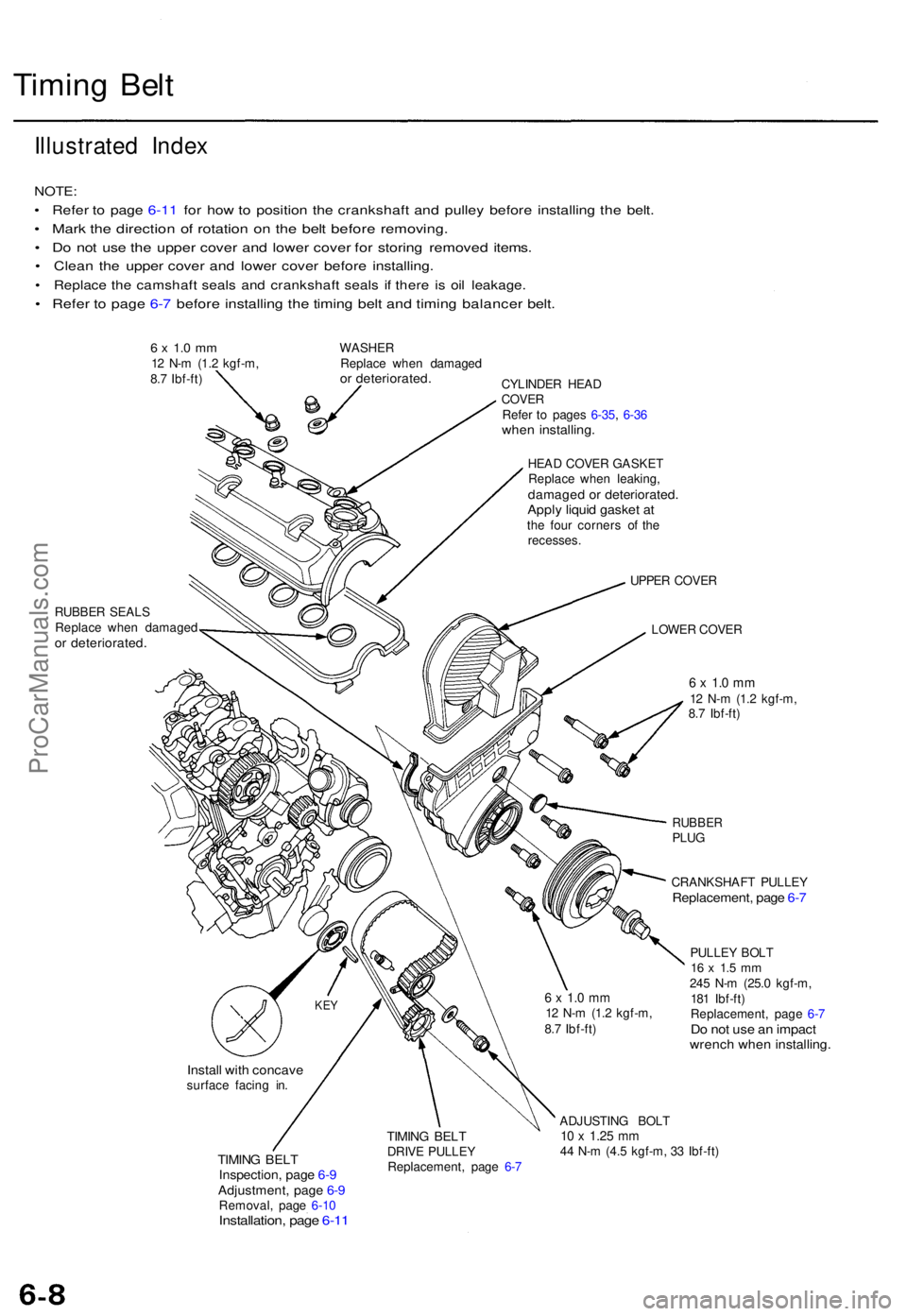
Timing Bel t
Illustrate d Inde x
NOTE :
• Refe r t o pag e 6-1 1 fo r ho w to positio n th e crankshaf t an d pulle y befor e installin g th e belt .
• Mar k th e directio n o f rotatio n o n th e bel t befor e removing .
• D o no t us e th e uppe r cove r an d lowe r cove r fo r storin g remove d items .
• Clea n th e uppe r cove r an d lowe r cove r befor e installing .
• Replac e th e camshaf t seal s an d crankshaf t seal s i f ther e i s oi l leakage .
• Refe r t o pag e 6- 7 befor e installin g th e timin g bel t an d timin g balance r belt .
6 x 1. 0 m m12 N- m (1. 2 kgf-m ,
8. 7 Ibf-ft ) WASHE
R
Replac e whe n damage dor deteriorated .CYLINDER HEA DCOVE RRefer t o page s 6-35 , 6-3 6whe n installing .
HEAD COVE R GASKE T
Replac e whe n leaking ,
damage d o r deteriorated .Apply liqui d gaske t a tth e fou r corner s o f th e
recesses .
RUBBE R SEAL S
Replac e whe n damage d
or deteriorated .
UPPER COVE R
LOWE R COVE R
6 x 1. 0 m m12 N- m (1. 2 kgf-m ,
8. 7 Ibf-ft )
RUBBE RPLUG
CRANKSHAF T PULLE Y
Replacement , pag e 6- 7
PULLE Y BOL T16 x 1. 5 m m245 N- m (25. 0 kgf-m ,
18 1 Ibf-ft )
Replacement , pag e 6- 7
Do no t us e a n impac twrench whe n installing .
Install wit h concav esurface facin g in .
TIMIN G BEL TInspection , pag e 6- 9Adjustment , pag e 6- 9Removal , pag e 6-1 0Installation , pag e 6-1 1
TIMIN G BEL TDRIV E PULLE Y
Replacement , pag e 6- 7 ADJUSTIN
G BOL T10 x 1.2 5 mm44 N- m (4. 5 kgf-m , 3 3 Ibf-ft )
KEY6 x 1. 0 m m12 N- m (1. 2 kgf-m ,
8. 7 Ibf-ft )
ProCarManuals.com
Page 745 of 1771
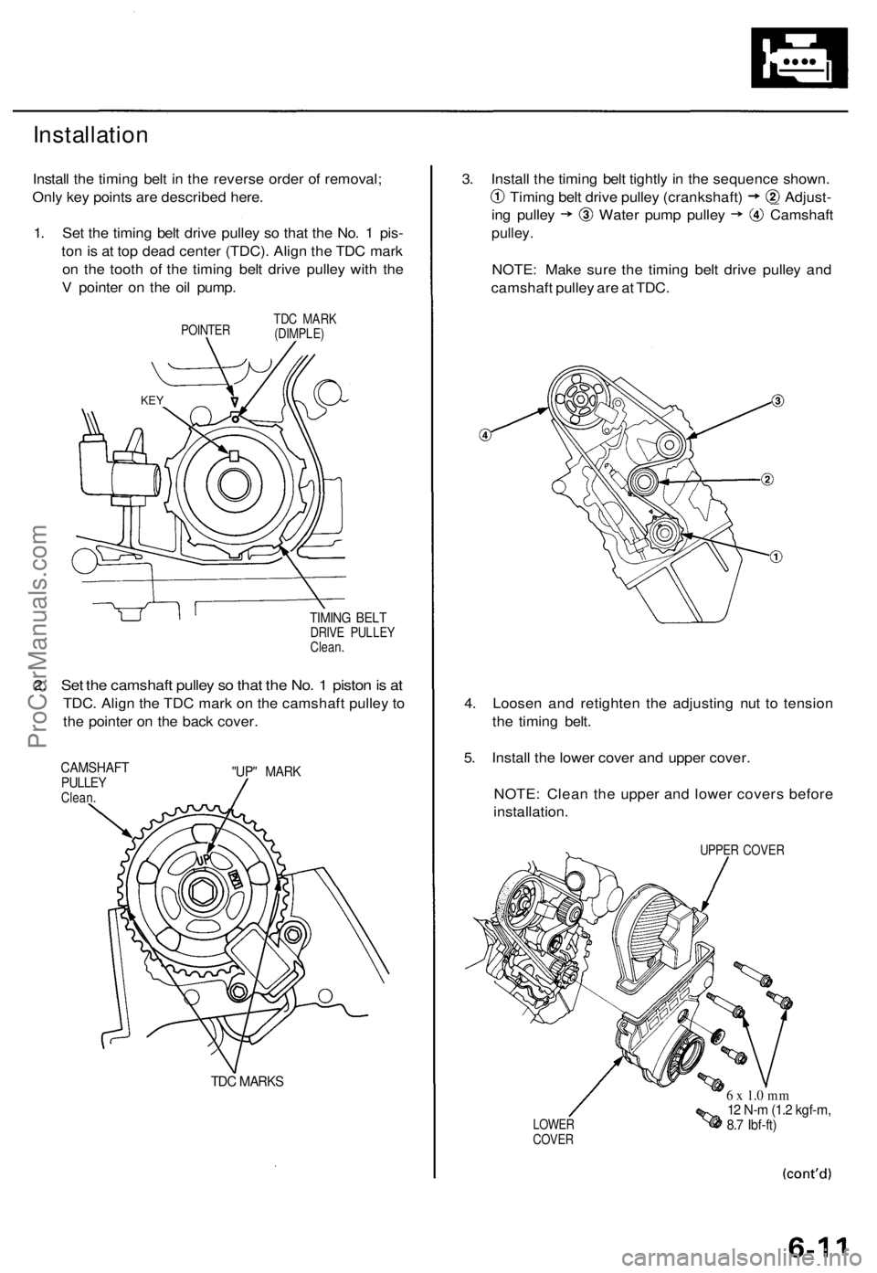
Installation
Install the timing belt in the reverse order of removal;
Only key points are described here.
1. Set the timing belt drive pulley so that the No. 1 pis-
ton is at top dead center (TDC). Align the TDC mark
on the tooth of the timing belt drive pulley with the
V pointer on the oil pump.
POINTER
TDC MARK
(DIMPLE)
TIMING BELT
DRIVE PULLEY
Clean.
2. Set the camshaft pulley so that the No. 1 piston is at
TDC. Align the TDC mark on the camshaft pulley to
the pointer on the back cover.
CAMSHAFT
PULLEY
Clean.
"UP" MARK
TDC MARKS
3. Install the timing belt tightly in the sequence shown.
Timing belt drive pulley (crankshaft) _ Adjust-
ing pulley Water pump pulley Camshaft
pulley.
NOTE: Make sure the timing belt drive pulley and
camshaft pulley are at TDC.
4. Loosen and retighten the adjusting nut to tension
the timing belt.
5. Install the lower cover and upper cover.
NOTE: Clean the upper and lower covers before
installation.
UPPER COVER
LOWER
COVER
6 x 1.0 mm
12 N-m (1.2 kgf-m,
8.7 Ibf-ft)
KEYProCarManuals.com
Page 746 of 1771
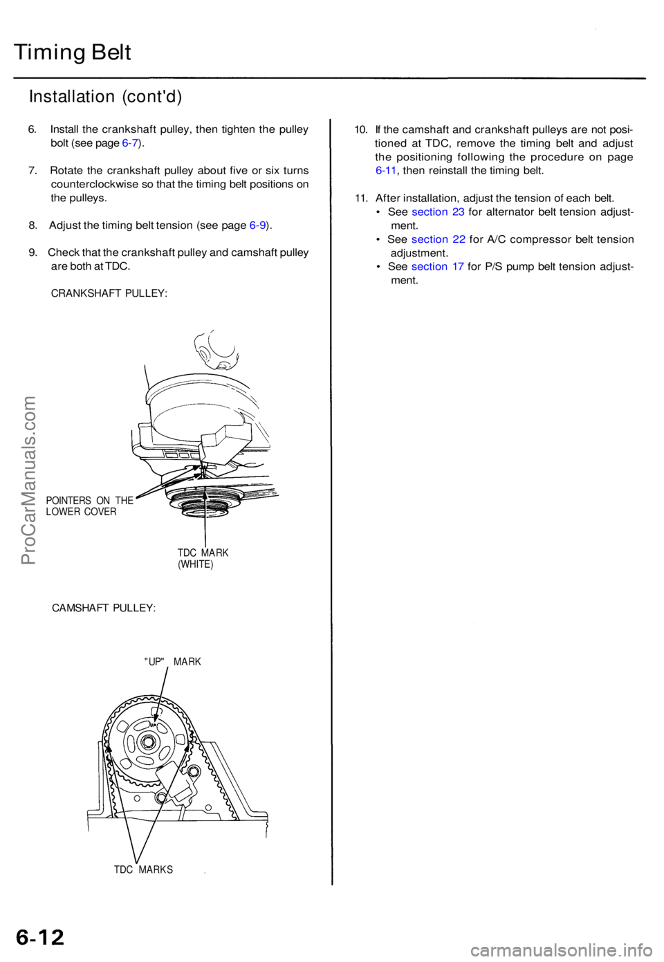
Timing Bel t
Installatio n (cont'd )
6. Instal l th e crankshaf t pulley , the n tighte n th e pulle y
bol t (se e pag e 6-7 ).
7 . Rotat e th e crankshaf t pulle y abou t fiv e o r si x turn s
counterclockwis e s o tha t th e timin g bel t position s o n
th e pulleys .
8 . Adjus t th e timin g bel t tensio n (se e pag e 6-9 ).
9 . Chec k tha t th e crankshaf t pulle y an d camshaf t pulle y
ar e bot h a t TDC .
CRANKSHAF T PULLEY :
POINTER S O N TH E
LOWE R COVE R
TDC MAR K
(WHITE )
CAMSHAF T PULLEY :
"UP" MAR K
TD C MARK S
10. I f th e camshaf t an d crankshaf t pulley s ar e no t posi -
tione d a t TDC , remov e th e timin g bel t an d adjus t
th e positionin g followin g th e procedur e o n pag e
6-11 , the n reinstal l th e timin g belt .
11 . Afte r installation , adjus t th e tensio n o f eac h belt .
• Se e sectio n 2 3 fo r alternato r bel t tensio n adjust -
ment .
• Se e sectio n 2 2 fo r A/ C compresso r bel t tensio n
adjustment .
• Se e sectio n 1 7 fo r P/ S pum p bel t tensio n adjust -
ment .
ProCarManuals.com
Page 798 of 1771
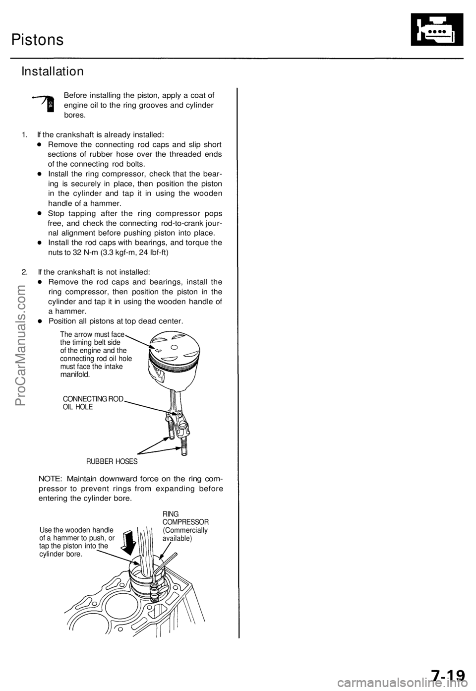
Pistons
Installation
Before installing the piston, apply a coat of
engine oil to the ring grooves and cylinder
bores.
1. If the crankshaft is already installed:
Remove the connecting rod caps and slip short
sections of rubber hose over the threaded ends
of the connecting rod bolts.
Install the ring compressor, check that the bear-
ing is securely in place, then position the piston
in the cylinder and tap it in using the wooden
handle of a hammer.
Stop tapping after the ring compressor pops
free, and check the connecting rod-to-crank jour-
nal alignment before pushing piston into place.
Install the rod caps with bearings, and torque the
nuts to 32 N-m (3.3 kgf-m, 24 Ibf-ft)
2. If the crankshaft is not installed:
Remove the rod caps and bearings, install the
ring compressor, then position the piston in the
cylinder and tap it in using the wooden handle of
a hammer.
Position all pistons at top dead center.
The arrow must face
the timing belt side
of the engine and the
connecting rod oil hole
must face the intake
manifold.
CONNECTING ROD
OIL HOLE
RUBBER HOSES
NOTE: Maintain downward force on the ring com-
pressor to prevent rings from expanding before
entering the cylinder bore.
Use the wooden handle
of a hammer to push, or
tap the piston into the
cylinder bore.
RING
COMPRESSOR
(Commercially
available)ProCarManuals.com