tire pressure ACURA TL 1995 Service Repair Manual
[x] Cancel search | Manufacturer: ACURA, Model Year: 1995, Model line: TL, Model: ACURA TL 1995Pages: 1771, PDF Size: 62.49 MB
Page 257 of 1771
Description
The automatic transmission is a combination of a 3-element torque converter and a dual-shaft electronically controlled
automatic transmission which provides 4 speeds forward and 1 reverse. The entire unit is positioned in line with the engine.
Torque Converter, Gears and Clutches
The torque converter consists of a pump, turbine, and stator, assembled in a single unit. They are connected to the engine
crankshaft so they turn together as a unit as the engine turns. Around the outside of the drive plate is a ring gear which
meshes with the starter pinion when the engine is being started.
The entire torque converter assembly serves as a flywheel while transmitting power to the transmission mainshaft.
The transmission has two parallel shafts: the mainshaft and the countershaft. The mainshaft is in line with the engine
crankshaft. The mainshaft includes the 1st, 4th and 2nd clutches and gears for 4th, 1st, 2nd and reverse (3rd gear is integral
with the mainshaft). The countershaft includes the 3rd, 1st-hold and reverse clutches, and gears for 3rd, 4th, 1st, 2nd,
reverse and parking. The secondary drive gear is integrated with the countershaft. The gears on the mainshaft are in con-
stant mesh with those on the countershaft. When certain combinations of gears in the transmission are engaged by clutch-
positions.
and
es, power is transmitted from the mainshaft to the countershaft to provide
Electronic Control
The electronic control system consists of a Powertrain Control Module (PCM), sensors, a linear solenoid and four solenoid
valves. Shifting and lock-up are electronically controlled for comfortable driving under all conditions.
The PCM is located below the dashboard, under the front lower panel on the passenger's side.
Hydraulic Control
The lower valve body assembly includes the main valve body, the secondary valve body, the throttle valve body, the lin-
ear solenoid, the shift control solenoid valves and the ATF passage body. They are bolted on the lower part of the trans-
mission housing. The regulator valve body, the ATF pump body, and the accumulator body are bolted to the torque con-
verter housing.
The main valve body on '96 model contains the manual valve, the 1-2 shift valve, the 2-3 shift valve, the 3-4 shift valve, the
4-3 kick-down valve and the Clutch Pressure Control (CPC) valve. The main valve body on '97 model contains the manual
valve, the 1-2 shift valve, the 2-3 shift valve, the 3-4 shift valve, the 4-3 kick-down valve and the main orifice control valve.
The secondary valve body on '96 model contains the 3-4 orifice control valve, the 4-3 shift timing valve, the modulator valve
and the accumulator pistons.The secondary valve body on '97 model contains the 3-4 orifice control valve, the 4-3 shift tim-
ing valve, the line pressure control valve, the modulator valve and the accumulator pistons. The throttle valve body
includes the throttle valve which is bolted onto the secondary valve body. The linear solenoid is joined to the throttle valve
body. The regulator valve body contains the regulator valve, the lock-up shift valve and the cooler relief valve. Fluid from
the regulator passes through the manual valve to the various control valves. The ATF pump body contains the lock-up tim-
ing valve, the lock-up control valve and the relief valve. The torque converter check valve is located in the torque converter
housing under the ATF pump body. The accumulator body contains the accumulator pistons. The reverse accumulator and
the 1st-hold accumulator pistons are assembled in the rear cover.
The 1st, 1st-hold, 2nd and reverse clutches receive fluid from their respective feed pipes, and the 3rd and 4th clutches
receive fluid from the internal hydraulic circuit.
Shift Control Mechanism
Input from various sensors located throughout the vehicle determines which shift control solenoid valve the PCM will acti-
vate. Activating a shift control solenoid valve changes modulator pressure, causing a shift valve to move. This pressurizes a
line to one of the clutches, engaging the clutch and its corresponding gear.
er through a fluid passage, causing the lock-up piston to be held against the torque converter cover. As this takes place, the
mainshaft rotates at the same speed as the engine crankshaft. Together with hydraulic control, the PCM optimizes the tim-
ing of the lock-up mechanism. The lock-up valves control the range of lock-up according to lock-up control solenoid valves
A and B, and throttle valve. When lock-up control solenoid valves A and B activate, modulator pressure changes. The lock-
up control solenoid valves A and B are mounted on the torque converter housing, and are controlled by the PCM.
(cont'd)
Lock-up Mechanism
In
position, in 2nd, 3rd, and 4th, and
position in 3rd, pressurized fluid is drained from the back of the torque convert-ProCarManuals.com
Page 492 of 1771
Component Location s Whee
l Alignmen t
Index
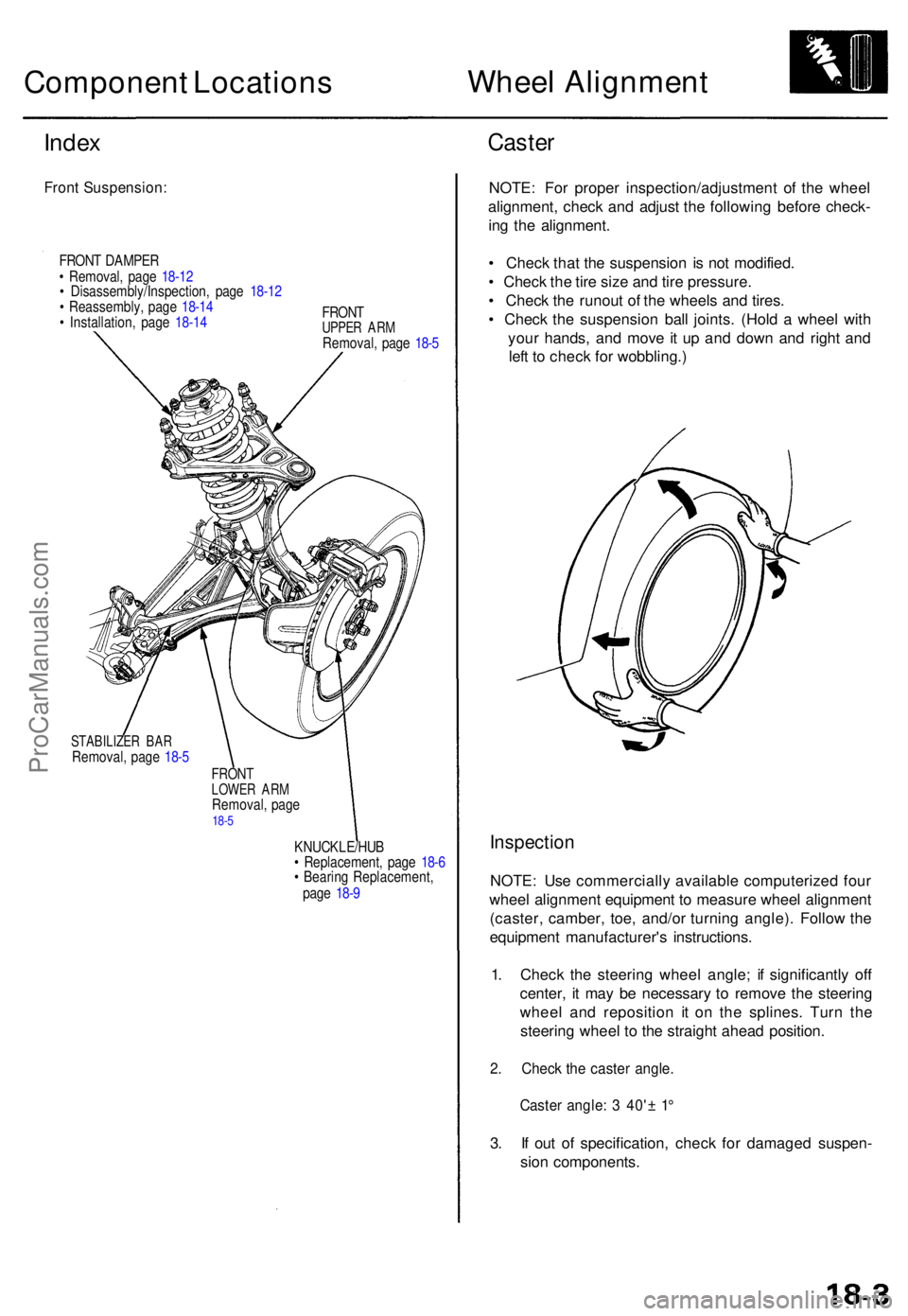
Fron t Suspension :
FRONT DAMPE R
• Removal , pag e 18-1 2
• Disassembly/Inspection , pag e 18-1 2
• Reassembly , pag e 18-1 4
• Installation , pag e 18-1 4 FRON
T
UPPER AR MRemoval , pag e 18- 5
STABILIZE R BA RRemoval , pag e 18- 5
FRON TLOWE R AR MRemoval , pag e18-5
KNUCKLE/HU B
• Replacement , pag e 18- 6
• Bearin g Replacement ,
pag e 18- 9
Caste r
NOTE : Fo r prope r inspection/adjustmen t of the whee l
alignment , chec k an d adjus t th e followin g befor e check -
in g th e alignment .
• Chec k tha t th e suspensio n i s no t modified .
• Chec k th e tir e siz e an d tir e pressure .
• Chec k th e runou t o f th e wheel s an d tires .
• Chec k th e suspensio n bal l joints . (Hol d a whee l wit h
you r hands , an d mov e i t u p an d dow n an d righ t an d
lef t t o chec k fo r wobbling. )
Inspection
NOTE: Us e commerciall y availabl e computerize d fou r
whee l alignmen t equipmen t t o measur e whee l alignmen t
(caster , camber , toe , and/o r turnin g angle) . Follo w th e
equipmen t manufacturer' s instructions .
1 . Chec k th e steerin g whee l angle ; i f significantl y of f
center , i t ma y b e necessar y t o remov e th e steerin g
whee l an d repositio n i t o n th e splines . Tur n th e
steerin g whee l t o th e straigh t ahea d position .
2. Chec k th e caste r angle .
Caster angle : 3 40' ± 1 °
3. I f ou t o f specification , chec k fo r damage d suspen -
sio n components .
ProCarManuals.com
Page 569 of 1771
A/C Service Tips and Precautions
The air
conditioner system uses
HFC-134a
(R-134a)
refrigerant
and
polyalkyleneglycol (PAG) refrigerant
oil*,
which
are not
compatible with CFC-12 (R-12) refrigerant and mineral oil. Do not use R-12 refrigerant or mineral oil in this system, and do
not attempt to use R-12 servicing equipment; damage to the air conditioner system or your servicing equipment will result.
*DENSO ND-OIL 8:
P/N 38897 - PR7 - A01AH: 120 (4 fl-oz, 4.2 Imp-oz)
P/N 38899 - PR7 - A01: 40 (1 1/3 fl-oz, 1.4 Imp-oz)
Use only service equipment that is U.L.-listed and is certified to meet the requirements of SAE J2210 to remove R-134a
from the air conditioner system.
CAUTION: Exposure to air conditioner refrigerant and lubricant vapor or mist can irritate eyes, nose and throat. Avoid
breathing the air conditioner refrigerant and lubricant vapor or mist.
If accidental system discharge occurs, ventilate work area before resuming service.
R-134a service equipment or vehicle air conditioner systems should not be pressure tested or leak tested with compressed
air.
Some mixtures of air and R-134a have been shown to be combustible at elevated pressures and can result
in tire or explosion causing injury or property damage. Never use compressed air to pressure test R-134a service equip-
ment or vehicle air conditioner systems.
Additional health and safety information may be obtained from the refrigerant and lubricant manufacturers.
1. Always disconnect the negative cable from the battery whenever replacing air conditioning parts.
2. Keep moisture and dust out of the system. When disconnecting any lines, plug or cap the fittings immediately; don't
remove the caps or plugs until just before you reconnect each line.
3. Before connecting any hose or line, apply a few drops of refrigerant oil to the O-ring.
4. When tightening or loosening a fitting, use a second wrench to support the matching fitting.
5. When discharging the system, use a R-134a refrigerant Recovery/Recycling/Charging System; don't release refriger-
ant into the atmosphere.
6. Add refrigerant oil after replacing the following parts:
NOTE:
To avoid contamination, do not return the oil to the container once dispensed, and never mix it with other refriger-
ant oils.
Immediately after using the oil, replace the cap on the container, and seal it to avoid moisture absorption.
Do not spill the refrigerant oil on the vehicle; it may damage the paint; if the refrigerant oil contacts the paint, wash
it off immediately.
Condenser ........................................ 25 (5/6 fl-oz, 0.9 Imp-oz)
Evaporator........................................ 50 (1 2/3 fl-oz, 1.8 Imp-oz)
Line or hose ...................................... 20 (2/3 fl-oz, 0.7 Imp-oz)
Receiver/Dryer
.................................
15
(1/2
fl-oz,
0.5
Imp-oz)
Leakage repair ................................. 25 (5/6 fl-oz, 0.9 Imp-oz)
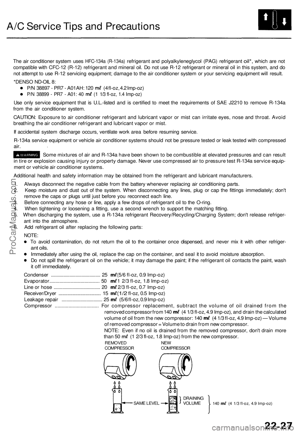
Compressor ................................ For compressor replacement, subtract the volume of oil drained from the
removed compressor from 140 (4 1/3 fl-oz, 4.9 Imp-oz), and drain the calculated
volume of oil from the new compressor: 140 (4 1/3 fl-oz, 4.9 Imp-oz) — Volume
of removed compressor = Volume to drain from new compressor.
NOTE: Even if no oil is drained from the removed compressor, don't drain more
than 50 (1 2/3 fl-oz, 1.8 Imp-oz) from the new compressor.
REMOVED NEW
COMPRESSOR COMPRESSOR
SAME LEVEL
140 (4 1/3 fl-oz, 4.9 Imp-oz)
DRAINING
VOLUMEProCarManuals.com
Page 936 of 1771
Description
The automatic transmission is a combination of a 3-element torque converter and a dual-shaft electronically controlled
automatic transmission which provides 4 speeds forward and 1 reverse. The entire unit is positioned in line with the engine.
Torque Converter, Gears and Clutches
The torque converter consists of a pump, turbine and stator, assembled in a single unit.
They are connected to the engine crankshaft so they turn together as a unit as the engine turns.
Around the outside of the drive plate is a ring gear which meshes with the starter pinion when the engine is being started.
The entire torque converter assembly serves as a flywheel while transmitting power to the transmission mainshaft.
The transmission has two parallel shafts: the mainshaft and the countershaft. The mainshaft is in line with the engine
crankshaft.
The mainshaft includes the 1st, 2nd and 4th clutches, and gears for 4th, 2nd, 1st and reverse (3rd gear is integral with the
mainshaft, while the reverse gear is integral with 4th gear).
The countershaft includes the 3rd, and 1st-hold clutches, and gears for 3rd, 4th, 1st, 2nd, reverse, and parking. The sec-
ondary drive gear is integrated with the countershaft.
The gears on the mainshaft are in constant mesh with those on the countershaft.
When certain combinations of gears in the transmission are engaged by clutches, power is transmitted from the mainshaft
to the countershaft to provide and positions.
Electronic Control
The electronic control system consists of the Transmission Control Module (TCM), sensors, a linear solenoid and four
solenoid valves. Shifting and lock-up are electronically controlled for comfortable driving under all conditions.
The TCM is located below the dashboard, behind the glove box on the passenger's side.
Hydraulic Control
The lower valve body assembly includes the main valve body, the servo body and the shift control solenoid valves. They
are bolted on the lower part of the transmission housing.
Other valve bodies, the regulator valve body, the ATF pump body, the 2nd accumulator body, and the throttle valve body,
are bolted to the torque converter housing.
The main valve body contains the manual valve, the 1 - 2 shift valve, the 2 - 3 shift valve, the 3 - 4 shift valve, the 4th kick-
down valve, the 2 - 3 orifice control valve, the 3 - 4 orifice control valve, the 4th exhaust valve, the servo control valve,
and the main orifice control valve.
The servo body contains the servo valve, 3rd and 4th accumulator pistons.
The regulator valve body contains the regulator valve, the lock-up shift valve, and the cooler relief valve.
Fluid from the regulator passes through the manual valve to the various control valves.
The throttle valve body includes the throttle valve which is bolted onto the 2nd accumulator body. The 2nd accumulator
piston is assembled in the 2nd accumulator body.
The linear solenoid is joined with the throttle valve body.
The ATF pump body contains the modulator valve, the lock-up control valve, the lock-up timing valve, and the relief valve.
The torque converter check valve is located in the torque converter housing under the ATF pump body.
The 1st and 1st-hold accumulator pistons are assembled in the rear cover.
The clutches receive fluid from their respective feed pipes or internal hydraulic circuit.
Shift Control Mechanism
Input from various sensors located throughout the vehicle determines which shift control solenoid valve the TCM will acti-
vate. Activating a shift control solenoid valve changes modulator pressure, causing a shift valve to move. This pressurizes
a line to one of the clutches, engaging that clutch and its corresponding gear.
Lock-up Mechanism
In position, in 2nd, 3rd and 4th, and in position in 3rd, pressurized fluid is drained from the back of the torque con-
verter through a fluid passage, causing the lock-up piston to be held against the torque converter cover. As this takes place,
the mainshaft rotates at the same speed as the engine crankshaft. Together with hydraulic control, the TCM optimizes the
timing of the lock-up mechanism. The lock-up valves control the range of lock-up according to lock-up control solenoid
valves A and B, and throttle valve. When lock-up control solenoid valves A and B activate, the modulator pressure changes.
The lock-up control solenoid valves A and B are mounted on the torque converter housing, and are controlled by the TCM.ProCarManuals.com
Page 1218 of 1771
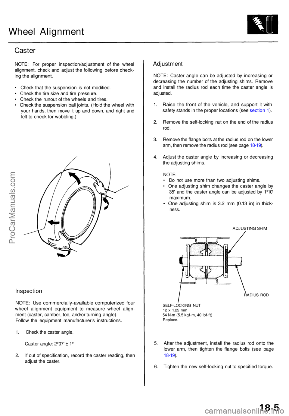
Wheel Alignmen t
Caster
NOTE : Fo r prope r inspection/adjustmen t o f th e whee l
alignment , chec k an d adjus t th e followin g befor e check -
ing th e alignment .
• Chec k tha t th e suspensio n i s no t modified .
• Chec k th e tir e siz e an d tir e pressure .
• Chec k th e runou t o f th e wheel s an d tires .
• Chec k th e suspensio n bal l joints . (Hol d th e whee l wit h
you r hands , the n mov e i t u p an d down , an d righ t an d
lef t t o chec k fo r wobbling. )
Inspection
NOTE: Us e commercially-availabl e computerize d fou r
whee l alignmen t equipmen t t o measur e whee l align -
men t (caster , camber , toe , and/o r turnin g angle) .
Follo w th e equipmen t manufacturer' s instructions .
1 . Chec k th e caste r angle .
Caste r angle : 2°07 ' ± 1 °
2 . I f ou t o f specification , recor d th e caste r reading , the n
adjus t th e caster .
Adjustmen t
NOTE: Caste r angl e ca n b e adjuste d b y increasin g o r
decreasin g th e numbe r o f th e adjustin g shims . Remov e
an d instal l th e radiu s ro d eac h tim e th e caste r angl e i s
adjusted .
1. Rais e th e fron t o f th e vehicle , an d suppor t i t wit h
safet y stand s in th e prope r location s (se e sectio n 1 ).
2 . Remov e th e self-lockin g nu t o n th e en d o f th e radiu s
rod.
3. Remov e th e flang e bolt s a t th e radiu s ro d o n th e lowe r
arm , the n remov e th e radiu s ro d (se e pag e 18-19 ).
4 . Adjus t th e caste r angl e b y increasin g o r decreasin g
the adjustin g shims .
NOTE:
• D o no t us e mor e tha n tw o adjustin g shims .
• On e adjustin g shi m change s th e caste r angl e b y
35 ' an d th e caste r angl e ca n b e adjuste d b y 1°10 '
maximum .
• On e adjustin g shi m is 3. 2 m m (0.1 3 in ) i n thick -
ness.
ADJUSTIN G SHI M
RADIU S RO D
SELF-LOCKIN G NU T
12 x 1.2 5 mm54 N- m (5. 5 kgf-m , 4 0 Ibf-ft )Replace .
5. Afte r th e adjustment , instal l th e radiu s ro d ont o th e
lowe r arm , the n tighte n th e flang e bolt s (se e pag e
18-19 ).
6 . Tighte n th e ne w self-lockin g nu t t o specifie d torque .
ProCarManuals.com
Page 1219 of 1771
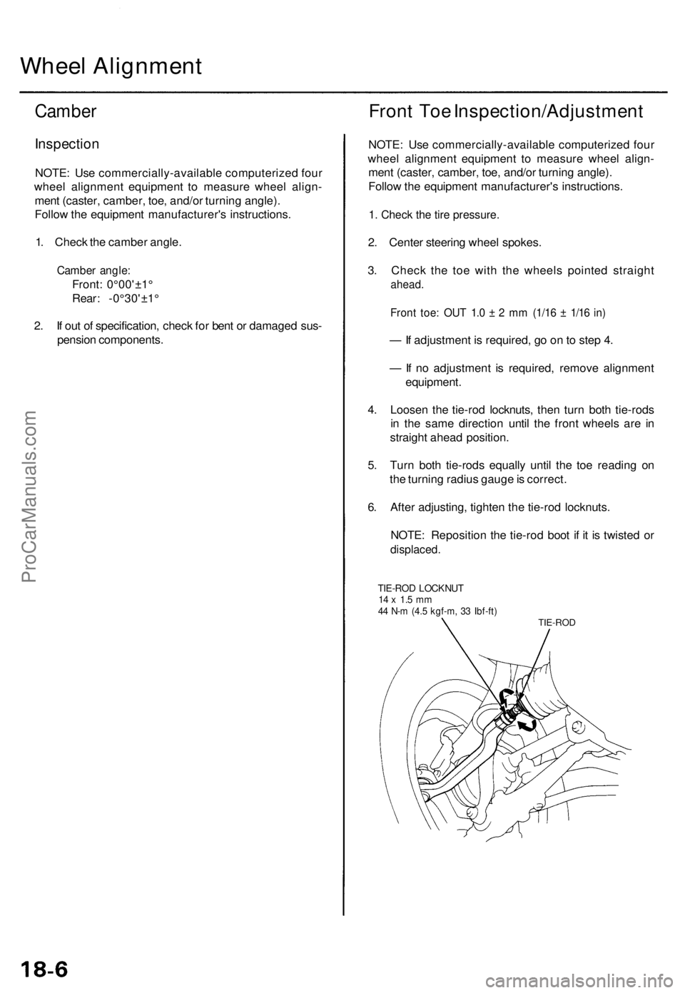
Wheel Alignmen t
Camber
Inspectio n
NOTE: Us e commercially-availabl e computerize d fou r
whee l alignmen t equipmen t t o measur e whee l align -
men t (caster , camber , toe , and/o r turnin g angle) .
Follo w th e equipmen t manufacturer' s instructions .
1 . Chec k th e cambe r angle .
Cambe r angle :
Front: 0°00'±1 °
Rear : -0°30'±1 °
2 . I f ou t o f specification , chec k fo r ben t o r damage d sus -
pensio n components .
Front To e Inspection/Adjustmen t
NOTE: Us e commercially-availabl e computerize d fou r
whee l alignmen t equipmen t t o measur e whee l align -
men t (caster , camber , toe , and/o r turnin g angle) .
Follo w th e equipmen t manufacturer' s instructions .
1. Check the tire pressure.
2. Cente r steerin g whee l spokes .
3 . Chec k th e to e wit h th e wheel s pointe d straigh t
ahead.
Front toe : OU T 1. 0 ± 2 m m (1/1 6 ± 1/1 6 in )
— If adjustmen t i s required , g o o n to ste p 4 .
— If n o adjustmen t i s required , remov e alignmen t
equipment .
4 . Loose n th e tie-ro d locknuts , the n tur n bot h tie-rod s
i n th e sam e directio n unti l th e fron t wheel s ar e i n
straigh t ahea d position .
5 . Tur n bot h tie-rod s equall y unti l th e to e readin g o n
th e turnin g radiu s gaug e is correct .
6 . Afte r adjusting , tighte n th e tie-ro d locknuts .
NOTE : Repositio n th e tie-ro d boo t i f i t i s twiste d o r
displaced .
TIE-ROD LOCKNU T14 x 1. 5 m m44 N- m (4. 5 kgf-m , 3 3 Ibf-ft )TIE-RO D
ProCarManuals.com