ESP Alfa Romeo 166 2007 Owner handbook (in English)
[x] Cancel search | Manufacturer: ALFA ROMEO, Model Year: 2007, Model line: 166, Model: Alfa Romeo 166 2007Pages: 272, PDF Size: 4.17 MB
Page 179 of 272

178
– Lower the lid (A-fig. 56) of the
boot trim corresponding with the light
concerned and remove the bulb holder
unit (B-fig. 57) releasing the retainer
catch (C).
– Remove and replace the bulb con-
cerned (spherical with bayonet coupling)
pushing gently and turning counter-clock-
wise (fig. 58):
(D) Reversing light bulb
(E) Rear fog guard bulb
(F) Sidelight bulb.GUARDS AND SIDELIGHTS
To replace the bulbs (Type B, 21W re-
versing light and rear fog guard, 5W side-
light):
– Open the boot.– Re-insert the bulb holder unit fasten-
ing it correctly in place using the retainer
catches (C-fig. 57).
– Shut the trim lid.
P4C00057611PGSm
fig. 56
606PGSm
fig. 57 fig. 58
607PGSm
Page 184 of 272

183
GLOVEBOX LIGHT
To replace the bulb (Type A, 5W):
– Remove the light pushing with a
screwdriver on the tab (A-fig. 76)
– Press the sides of the bulb screen (B-
fig. 77) in correspondence with the two
fastening pins and turn it. – Remove the screen (B-fig. 74) re-
leasing it from the catches (C-fig. 74)
– Remove the bulb (D-fig. 75)
pulling outwards and releasing from the
side contacts.
– Insert the new bulb making sure that
it is positioned correctly and locked be-
tween the contacts.
– Refit the screen (B-fig. 74) insert-
ing it correctly between the catches (C-
fig. 74).– Refit the light unit firstly inserting
from the side (E-fig. 75) and then
pressing on the other side until the catch
clicks into place (F-fig. 75).
P4C00057495PGSm
fig. 74
496PGSm
fig. 75
630PGSm
fig. 76
Page 185 of 272

184
– Change the bulb (C-fig. 77) which
is pressure-fitted.
– Re-position the screen inserting the
two fastening pins.
– Re-install the light inserting it in the
correct position firstly on one side (D-
fig. 76) and then pushing on the other
until the tab clicks.DOOR LIGHTS
To replace the bulb (Type A, 5W):
– Remove the light pushing with a
screwdriver on the tab (A-fig. 78).
– Press on the side of the screen (B-
fig. 79) in correspondence with the two
fastening pins and turn it.– Change the bulb (C-fig. 79) which
is pressure-fitted.
– Re-position the screen inserting the
two fastening pins.
– Re-install the light inserting it firstly
on one side (D-fig. 78) and then push-
ing on the other until the tab clicks.
628PGS
fig. 79
629PGSm
fig. 77
502PGSm627PGSm
fig. 78
Page 188 of 272
187
FUSES AND RELAYS IN THE
CONTROL UNIT
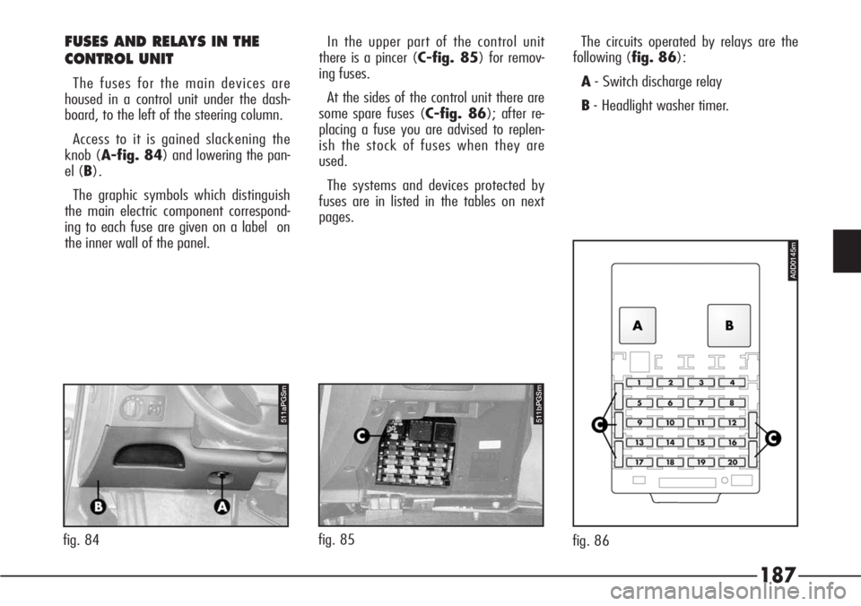
The fuses for the main devices are
housed in a control unit under the dash-
board, to the left of the steering column.
Access to it is gained slackening the
knob (A-fig. 84) and lowering the pan-
el (B).
The graphic symbols which distinguish
the main electric component correspond-
ing to each fuse are given on a label on
the inner wall of the panel.In the upper part of the control unit
there is a pincer (C-fig. 85) for remov-
ing fuses.
At the sides of the control unit there are
some spare fuses (C-fig. 86); after re-
placing a fuse you are advised to replen-
ish the stock of fuses when they are
used.
The systems and devices protected by
fuses are in listed in the tables on next
pages.The circuits operated by relays are the
following (fig. 86):
A- Switch discharge relay
B- Headlight washer timer.
511bPGSm
fig. 85
511aPGSm
fig. 84
A0D0145m
fig. 86
Page 199 of 272

198IN THE EVENT
OF AN ACCIDENT
– It is important to keep calm.
– If you are not directly involved, stop
at a distance of at least ten metres from
the accident.
– On the motorway stop without ob-
structing the emergency lane.
– Turn off the engine and switch on the
hazard warning lights.
– At night, light the place of the acci-
dent with your headlights.
– Take care not to put yourself in dan-
ger of being run over.
– Signal the accident placing the reflect-
ing triangle plainly in view at the regula-
tion distance.
– Call the rescue organisation giving in-
formation as exact as possible. On motor-
ways use the special call boxes.
– In motorway pileups, especially with
poor visibility, the risk exists of being in-
volved in other crashes. Leave the vehi-
cle immediately and go over the guard
rail. The car is to be lifted
positioning the jack or
the workshop lift arm
plate only in the points shown
(1-2 fig. 100).
Between the lift plate and the
body interpose a rubber pad
with a maximum size of 60x60
mm and maximum thickness of
30 mm. The pad should insert in
the special recess on the under
door panel, without interfering
with it.
USING AN ARM LIFT OR
WORKSHOP LIFT
The vehicle must only be lifted laterally
positioning the ends of the arms or the
workshop lift in the areas (1-2) illustrat-
ed, approx. 30 cm from the profile of the
wheelhouse (fig. 100).
A0D0040m
fig. 100
Page 208 of 272
207
IMPORTANT - Engine oil
Change the engine oil more frequently
than stated in the Scheduled Mainte-
nance Programme if the car is used pre-
vailingly in one of the following particular-
ly harsh conditions:
– trailer or caravan towing
– dusty roads
– short, repeated journeys (less than 7-
8 km) with an outside temperature of be-
low freezing point.
– engine idling frequently or driving
long distances at low speed (e.g. taxi or
door-to-door deliveries) or in the case of
prolonged inactivity.
IMPORTANT - Air cleaner
Using the car on dusty roads, change
the air cleaner more frequently than stat-
ed in the Scheduled Maintenance Pro-
gramme.
For any doubts about the intervals be-
tween engine oil and air cleaner changes
in relation to how the car is used, contact
Authorised Alfa Romeo Services.IMPORTANT - Fuel oil filter
The variety of the degree of purity of
the fuel oil in commerce may make it
necessary to change the fuel oil filter
more frequently than stated in the Sched-
uled Maintenance Programme. If the en-
gine is “sobbing” it is a sign that the fil-
ter needs changing.
IMPORTANT - Pollen filter
If the car is used frequently in dusty or
heavily polluted environments, you are
recommended to change the activated
carbon filtering element more frequently;
in particular, it should be changed if a
lower flow of air admitted to the passen-
ger compartment is noted.IMPORTANT - Batteries
You are recommended to have the bat-
tery charge conditions checked, prefer-
ably at the onset of winter, to avoid the
possibility of freezing the electrolyte.
This check should be carried out more
frequently if the car is used prevailingly
for short journeys, or if it is fitted with
services that absorb high amounts of cur-
rent permanently with the ignition key
off, especially if installed in the after mar-
ket.
In the case of use of the car in hot cli-
mates or particularly harsh conditions, it
is wise to check the level of the battery
fluid (electrolyte) at more frequent inter-
vals than stated in the Scheduled Mainte-
nance Programme.
IMPORTANT - Remote control
If when pressing the remote control but-
ton of the key, the operating led on the
key flashes briefly only once, the battery
need replacing with other of the same
type.
Page 212 of 272
211
PROTECTIVE SHIELD UNDER
ENGINE
The car is fitted with a protective shield
under the engine.
IMPORTANTWhen changing the en-
gine oil and filter, checking and changing
the gearbox and differential oil, this pro-
tection should be removed. This operation
should be carried out by Alfa Romeo Au-
thorized Services.
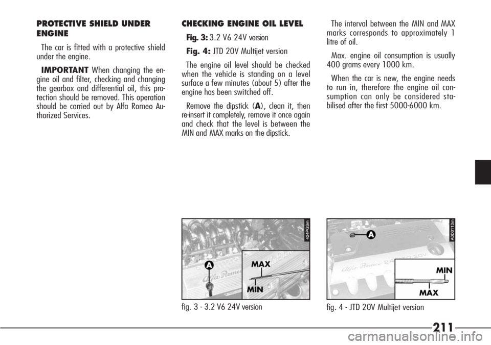
CHECKING ENGINE OIL LEVEL
Fig. 3:3.2 V6 24V version
Fig. 4:JTD 20V Multijet version
The engine oil level should be checked
when the vehicle is standing on a level
surface a few minutes (about 5) after the
engine has been switched off.
Remove the dipstick (A), clean it, then
re-insert it completely, remove it once again
and check that the level is between the
MIN and MAX marks on the dipstick.The interval between the MIN and MAX
marks corresponds to approximately 1
litre of oil.
Max. engine oil consumption is usually
400 grams every 1000 km.
When the car is new, the engine needs
to run in, therefore the engine oil con-
sumption can only be considered sta-
bilised after the first 5000-6000 km.
fig. 3 - 3.2 V6 24V version
424PGSm
fig. 4 - JTD 20V Multijet version
A0D0113m
Page 216 of 272
215
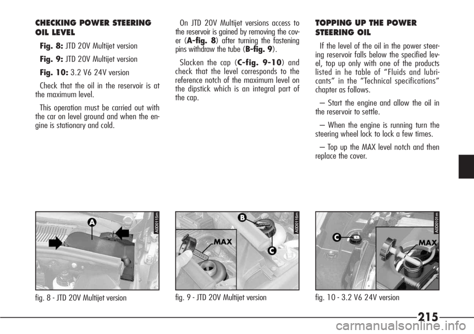
CHECKING POWER STEERING
OIL LEVEL
Fig. 8:JTD 20V Multijet version
Fig. 9:JTD 20V Multijet version
Fig. 10:3.2 V6 24V version
Check that the oil in the reservoir is at
the maximum level.
This operation must be carried out with
the car on level ground and when the en-
gine is stationary and cold.
fig. 8 - JTD 20V Multijet versionfig. 9 - JTD 20V Multijet versionfig. 10 - 3.2 V6 24V version On JTD 20V Multijet versions access to
the reservoir is gained by removing the cov-
er (A-fig. 8) after turning the fastening
pins withdraw the tube (B-fig. 9).
Slacken the cap (C-fig. 9-10) and
check that the level corresponds to the
reference notch of the maximum level on
the dipstick which is an integral part of
the cap.
TOPPING UP THE POWER
STEERING OIL
If the level of the oil in the power steer-
ing reservoir falls below the specified lev-
el, top up only with one of the products
listed in he table of “Fluids and lubri-
cants” in the “Technical specifications”
chapter as follows.
– Start the engine and allow the oil in
the reservoir to settle.
– When the engine is running turn the
steering wheel lock to lock a few times.
– Top up the MAX level notch and then
replace the cover.
A0D0115mA0D0101mA0D0116m
Page 221 of 272

220
Serious damage may be
caused to the vehicle if
electrical accessories
are incorrectly installed. If, after
purchasing your vehicle, you
wish to install accessories (theft
alarm, voice feature, satellite ra-
dio-navigator with antitheft
function, etc.) contact Alfa
Romeo Authorized Services
whose qualified personnel in ad-
dition to being able to recom-
mend the most suitable devices
from Lineaccessori will determine
whether it will be necessary to
install a more powerful battery.
If the car is to remain
stationary for a long
time in very cold weath-
er, remove the battery and take it
to a warm place, otherwise it
might freeze.
The battery adopted is of the “Limited
Maintenance” type and under normal
conditions of use will not require topping
up.
The level of the electrolyte solution
must however be between the MIN and
MAX reference marks when the vehicle is
stationary on a level surface (fig. 16).
If the level is low, con-
tact Alfa Romeo Autho-
rized Services.The batteries contain
substances which are
extremely harmful to
the environment. Alfa Romeo
Authorized Services should be
contacted when equipped to dis-
pose of the batteries respecting
both the environment and legal
requirements.
3101CAm
fig. 16
A0D0107m
fig. 15
Page 224 of 272
223
– If electrical welding is to be carried
out on the body of the vehicle the elec-
tronic control units must be disconnected
or removed if the work involves the pro-
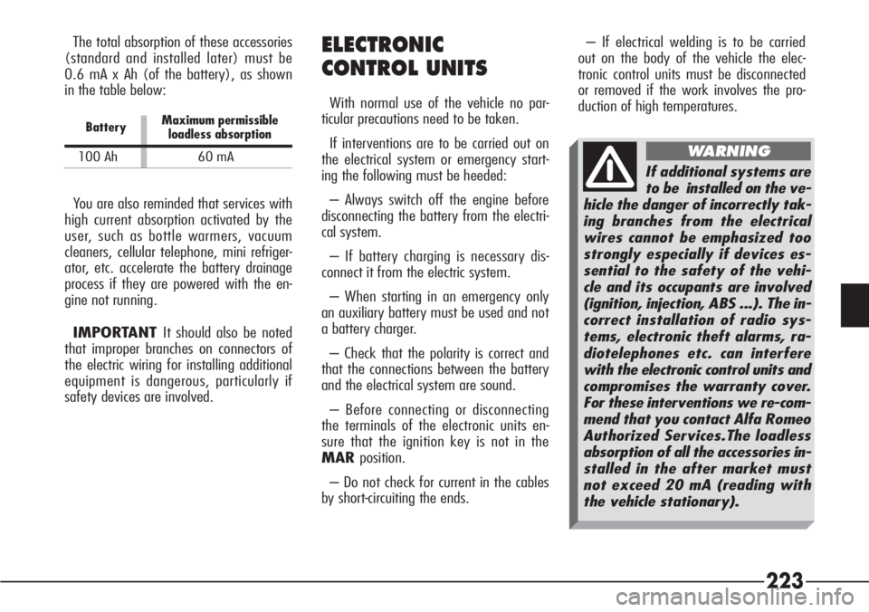
duction of high temperatures.The total absorption of these accessories
(standard and installed later) must be
0.6 mA x Ah (of the battery), as shown
in the table below:
BatteryMaximum permissible loadless absorption
100 Ah 60 mA
You are also reminded that services with
high current absorption activated by the
user, such as bottle warmers, vacuum
cleaners, cellular telephone, mini refriger-
ator, etc. accelerate the battery drainage
process if they are powered with the en-
gine not running.
IMPORTANT It should also be noted
that improper branches on connectors of
the electric wiring for installing additional
equipment is dangerous, particularly if
safety devices are involved.
ELECTRONIC
CONTROL UNITS
With normal use of the vehicle no par-
ticular precautions need to be taken.
If interventions are to be carried out on
the electrical system or emergency start-
ing the following must be heeded:
– Always switch off the engine before
disconnecting the battery from the electri-
cal system.
– If battery charging is necessary dis-
connect it from the electric system.
– When starting in an emergency only
an auxiliary battery must be used and not
a battery charger.
– Check that the polarity is correct and
that the connections between the battery
and the electrical system are sound.
– Before connecting or disconnecting
the terminals of the electronic units en-
sure that the ignition key is not in the
MARposition.
– Do not check for current in the cables
by short-circuiting the ends.
If additional systems are
to be installed on the ve-
hicle the danger of incorrectly tak-
ing branches from the electrical
wires cannot be emphasized too
strongly especially if devices es-
sential to the safety of the vehi-
cle and its occupants are involved
(ignition, injection, ABS ...). The in-
correct installation of radio sys-
tems, electronic theft alarms, ra-
diotelephones etc. can interfere
with the electronic control units and
compromises the warranty cover.
For these interventions we re-com-
mend that you contact Alfa Romeo
Authorized Services.The loadless
absorption of all the accessories in-
stalled in the after market must
not exceed 20 mA (reading with
the vehicle stationary).
WARNING