Alfa Romeo MiTo 2009 Owner handbook (in English)
Manufacturer: ALFA ROMEO, Model Year: 2009, Model line: MiTo, Model: Alfa Romeo MiTo 2009Pages: 250, PDF Size: 4.61 MB
Page 161 of 250
160IN AN EMERGENCY
STARTING THE ENGINE
If the Ywarning light in the instrument panel remains on con-
stantly, contact an Alfa Romeo Authorised Service Provider imme-
diately.
STARTING WITH AN AUXILIARY BATTERY
If the battery is flat, the engine may be started using an auxiliary
battery with the same capacity or a little higher than the flat one.
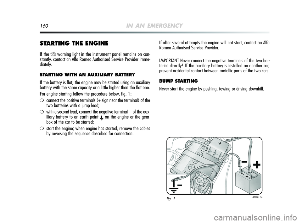
For engine starting follow the procedure below, fig. 1:
❍connect the positive terminals (+ sign near the terminal) of the
two batteries with a jump lead;
❍with a second lead, connect the negative terminal – of the aux-
iliary battery to an earth point
Eon the engine or the gear-
box of the car to be started;
❍start the engine; when engine has started, remove the cables
by reversing the sequence described for connection.If after several attempts the engine will not start, contact an Alfa
Romeo Authorised Service Provider.
IMPORTANT Never connect the negative terminals of the two bat-
teries directly! If the auxiliary battery is installed on another car,
prevent accidental contact between metallic parts of the two cars.
BUMP STARTING
Never start the engine by pushing, towing or driving downhill.
fig. 1A0J0111m
159-196 Alfa MiTo GB 12-11-2008 15:45 Pagina 160
Page 162 of 250
IN AN EMERGENCY161
4
The small spare wheel is specific to the vehicle: do
not use it on different vehicle models or use spare
wheels from other models on your car. The small
spare wheel must only be used in an emergency. Never
use it longer than strictly necessary and never exceed 80
km/h. On the small spare wheel there is a label, sum-
marizing the main warnings about the small spare wheel
usage restrictions. Never remove or cover the label. Nev-
er apply any hub cap to the small spare wheel.
REPLACING A WHEEL
GENERAL INSTRUCTIONS
The vehicle is equipped with the“Fix&Go automatic kit”: to use
this device see the paragraph entitled “Fix&Go Automatic Kit”.
As an alternative to the “Fix&Go Automatic Kit” the vehicle can be
provided with a small spare wheel: see the instructions on the fol-
lowing pages for changing the wheels.
Indicate that the car is stationary according to the
laws in force: emergency lights, refracting warn-
ing triangle, etc. Passengers should leave the car,
particularly if it is heavily loaded, and wait for the wheel
to be changed away from on-coming traffic. In the event
of a wheel change on a slope or on unsurfaced roads,
chock the rear wheels.
159-196 Alfa MiTo GB 12-11-2008 15:45 Pagina 161
Page 163 of 250
162IN AN EMERGENCY
The jack may only be used to replace wheels on
the car to which it is fitted or other cars of the same
model. Never use the jack for other purposes, such
as lifting other car models. Never use the jack to carry out
repairs under the car. Incorrect positioning of the jack may
cause the car to fall. Do not use the jack for loads greater
than those shown on the label. Never install snow chains
on the small spare wheel; if a front tyre (driving wheel)
is punctured and you need to use snow chains, use a stan-
dard wheel from the rear axle and install the small spare
wheel on the rear axle. This way, with two normal front
driving wheels, you can install the snow chains on them.
If the hub cap is not installed properly, it can de-
tach itself when the vehicle is running. Never tam-
per with the inflation valve. Never introduce tools
of any kind between rim and tyre. Regularly check the in-
flation pressure of the tyres and small spare wheel (see
chapter 6).
Vehicle handling is modified with the small spare
wheel fitted. Avoid violent accelerations and brak-
ing, sharp steering and fast cornering. The over-
all lifetime of the small spare wheel is about 3000 km,
after which the relevant tyre must be replaced with an-
other one of the same type. Never install a traditional tyre
on a rim designed to be used as a small spare wheel. Re-
pair and refit the standard wheel as soon as possible. Us-
ing two or more small spare wheels at the same time is
forbidden. Do not apply grease to the bolt threading be-
fore assembly: they might loosen spontaneously.
159-196 Alfa MiTo GB 12-11-2008 15:45 Pagina 162
Page 164 of 250
IN AN EMERGENCY163
4
JACK
Important notes:
❍the jack weight is 1.76 kg;
❍the jack requires no adjustment;
❍the jack cannot be repaired; if it breaks it must be replaced with
a new jack;
❍no tool other than the cranking device may be fitted on the
jack.Replace the wheel as follows:
❍stop the car in a position where it does not endanger on-com-
ing traffic and where you can replace the wheel safely. The
ground must be flat and compact;
❍switch off the engine, pull up the handbrake and engage 1st
gear or reverse; put on the high visibility jacket (required by
law) before leaving the vehicle;
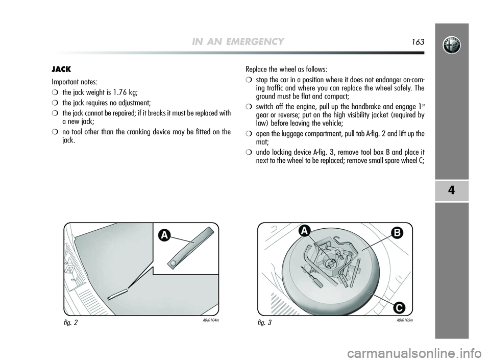
❍open the luggage compartment, pull tab A-fig. 2 and lift up the
mat;
❍undo locking device A-fig. 3, remove tool box B and place it
next to the wheel to be replaced; remove small spare wheel C;
fig. 2A0J0104mfig. 3A0J0105m
159-196 Alfa MiTo GB 12-11-2008 15:45 Pagina 163
Page 165 of 250
164IN AN EMERGENCY
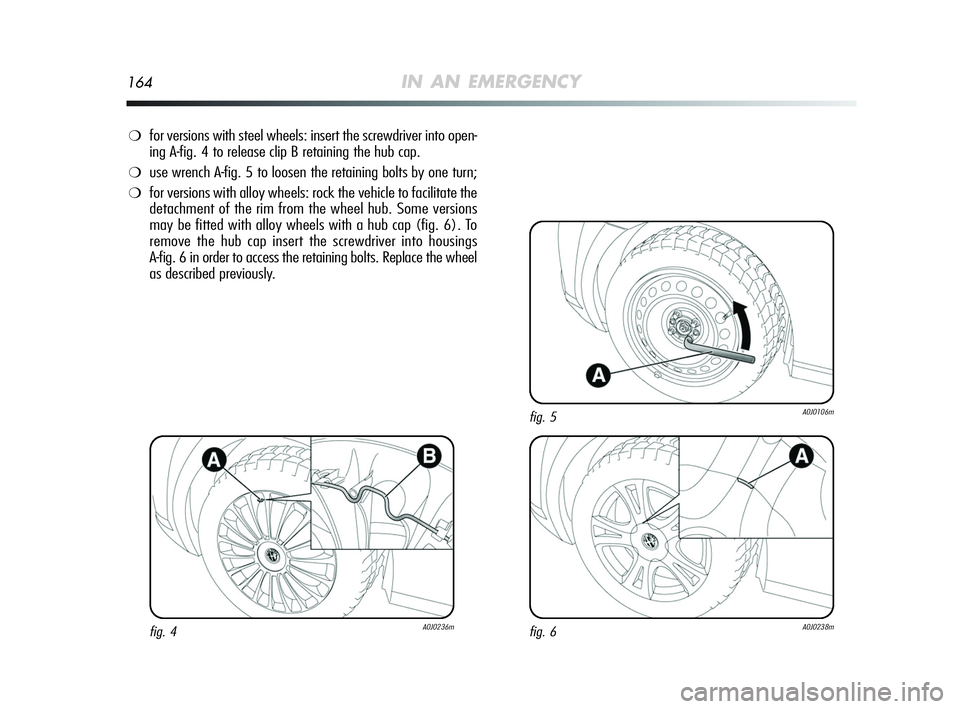
❍for versions with steel wheels: insert the screwdriver into open-
ing A-fig. 4 to release clip B retaining the hub cap.
❍use wrench A-fig. 5 to loosen the retaining bolts by one turn;
❍for versions with alloy wheels: rock the vehicle to facilitate the
detachment of the rim from the wheel hub. Some versions
may be fitted with alloy wheels with a hub cap (fig. 6). To
remove the hub cap insert the screwdriver into housings
A-fig. 6 in order to access the retaining bolts. Replace the wheel
as described previously.
fig. 4A0J0236mfig. 6A0J0238m
fig. 5A0J0106m
159-196 Alfa MiTo GB 12-11-2008 15:45 Pagina 164
Page 166 of 250
IN AN EMERGENCY165
4
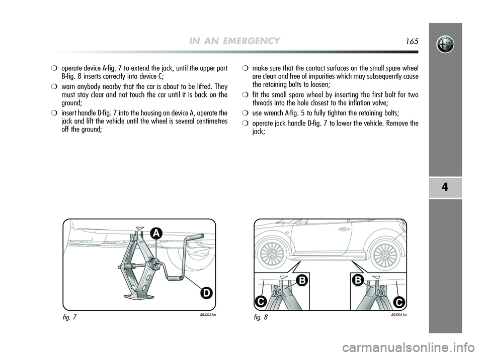
❍operate device A-fig. 7 to extend the jack, until the upper part
B-fig. 8 inserts correctly into device C;
❍warn anybody nearby that the car is about to be lifted. They
must stay clear and not touch the car until it is back on the
ground;
❍insert handle D-fig. 7 into the housing on device A, operate the
jack and lift the vehicle until the wheel is several centimetres
off the ground;
❍make sure that the contact surfaces on the small spare wheel
are clean and free of impurities which may subsequently cause
the retaining bolts to loosen;
❍fit the small spare wheel by inserting the first bolt for two
threads into the hole closest to the inflation valve;
❍use wrench A-fig. 5 to fully tighten the retaining bolts;
❍operate jack handle D-fig. 7 to lower the vehicle. Remove the
jack;
fig. 7A0J0062mfig. 8A0J0061m
159-196 Alfa MiTo GB 12-11-2008 15:45 Pagina 165
Page 167 of 250
166IN AN EMERGENCY
fig. 9A0J0271mfig. 10A0J0180m
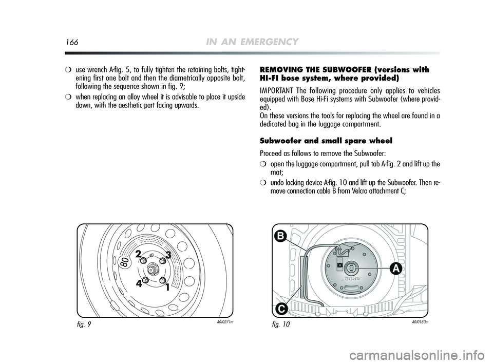
❍use wrench A-fig. 5, to fully tighten the retaining bolts, tight-
ening first one bolt and then the diametrically opposite bolt,
following the sequence shown in fig. 9;
❍when replacing an alloy wheel it is advisable to place it upside
down, with the aesthetic part facing upwards.
REMOVING THE SUBWOOFER (versions with
HI-FI bose system, where provided)
IMPORTANT The following procedure only applies to vehicles
equipped with Bose Hi-Fi systems with Subwoofer (where provid-
ed).
On these versions the tools for replacing the wheel are found in a
dedicated bag in the luggage compartment.
Subwoofer and small spare wheel
Proceed as follows to remove the Subwoofer:
❍open the luggage compartment, pull tab A-fig. 2 and lift up the
mat;
❍undo locking device A-fig. 10 and lift up the Subwoofer. Then re-
move connection cable B from Velcro attachment C;
159-196 Alfa MiTo GB 12-11-2008 15:45 Pagina 166
Page 168 of 250
IN AN EMERGENCY167
4
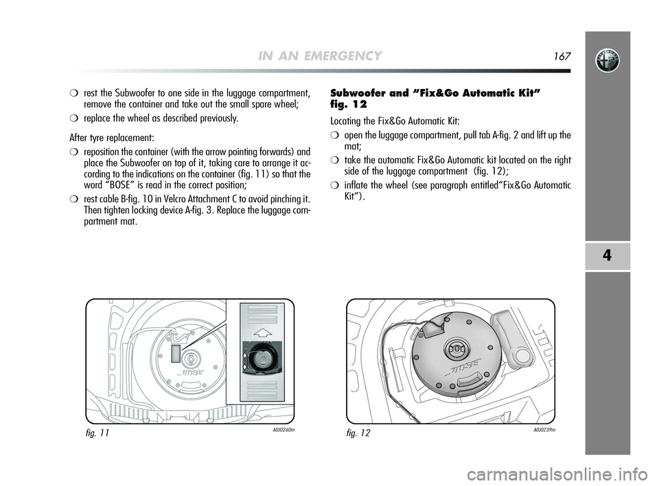
❍rest the Subwoofer to one side in the luggage compartment,
remove the container and take out the small spare wheel;
❍replace the wheel as described previously.
After tyre replacement:
❍reposition the container (with the arrow pointing forwards) and
place the Subwoofer on top of it, taking care to arrange it ac-
cording to the indications on the container (fig. 11) so that the
word “BOSE” is read in the correct position;
❍rest cable B-fig. 10 in Velcro Attachment C to avoid pinching it.
Then tighten locking device A-fig. 3. Replace the luggage com-
partment mat.
Subwoofer and “Fix&Go Automatic Kit”
fig. 12
Locating the Fix&Go Automatic Kit:
❍open the luggage compartment, pull tab A-fig. 2 and lift up the
mat;
❍take the automatic Fix&Go Automatic kit located on the right
side of the luggage compartment (fig. 12);
❍inflate the wheel (see paragraph entitled“Fix&Go Automatic
Kit”).
fig. 11A0J0260mfig. 12A0J0239m
159-196 Alfa MiTo GB 12-11-2008 15:45 Pagina 167
Page 169 of 250
168IN AN EMERGENCY
REFITTING THE WHEEL
Following the procedure described previously, raise the car and re-
move the small spare wheel.
Proceed as follows:
❍make sure the contact surfaces between spare wheel and hub
are clean so that the fastening bolts will not come loose;
❍tighten the retaining bolts using wrench A-fig. 4;
❍lower the car and remove the jack;
❍use wrench A-fig. 4 to fully tighten the bolts, following the se-
quence shown in fig. 9;
❍for versions with steel rims: secure the wheel hub to the rim;
❍for versions with alloy rims with hub cap: align the pin on the
cap with the seat on the rim.
After tyre replacement:stow the small spare wheel in
the space provided in the boot; place the jack and other tools
into their container; place the container, complete with tools on
the small spare wheel; replace the luggage compartment mat.
159-196 Alfa MiTo GB 12-11-2008 15:45 Pagina 168
Page 170 of 250
IN AN EMERGENCY169
4
“Fix&Go Automatic” KIT
This is located in the luggage compartment. The Kit container al-
so contains a screwdriver and the ring. The kit includes:
❍a cylinder A-fig. 13 containing sealing fluid and fitted with: a
filling pipe B and adhesive label C with the words“max. 80
km/h”, to be attached in a position easily visible to the dri-
ver (on the dashboard) after tyre repair;
❍a compressor D complete with pressure gauge and connectors;
❍an information booklet fig. 14, providing instructions for us-
ing the kit correctly. This booklet should be given to the per-
sons charged with handling the tyre treated with this kit;
❍a pair of gloves located in the side compartment of the com-
pressor;
❍adapters for inflating different elements.IMPORTANT The sealing fluid is effective with external tempera-
tures between –20 °C and +50 °C. The sealing fluid also has an
expiry date.
fig. 13A0J0112mfig. 14A0J0113m
Hand over the instruction booklet to the personnel
charged with treating the tyre repaired with the
Fix&Go Automatic kit.
In the event of a puncture caused by foreign bod-
ies, the kit may be used to repair tyres showing
damage to the track or shoulder up to a maximum
diameter of 4 mm.
159-196 Alfa MiTo GB 12-11-2008 15:45 Pagina 169