ESP ASTON MARTIN DB7 1997 User Guide
[x] Cancel search | Manufacturer: ASTON MARTIN, Model Year: 1997, Model line: DB7, Model: ASTON MARTIN DB7 1997Pages: 421, PDF Size: 9.31 MB
Page 305 of 421
Air Conditioning
Vacuum System •^^
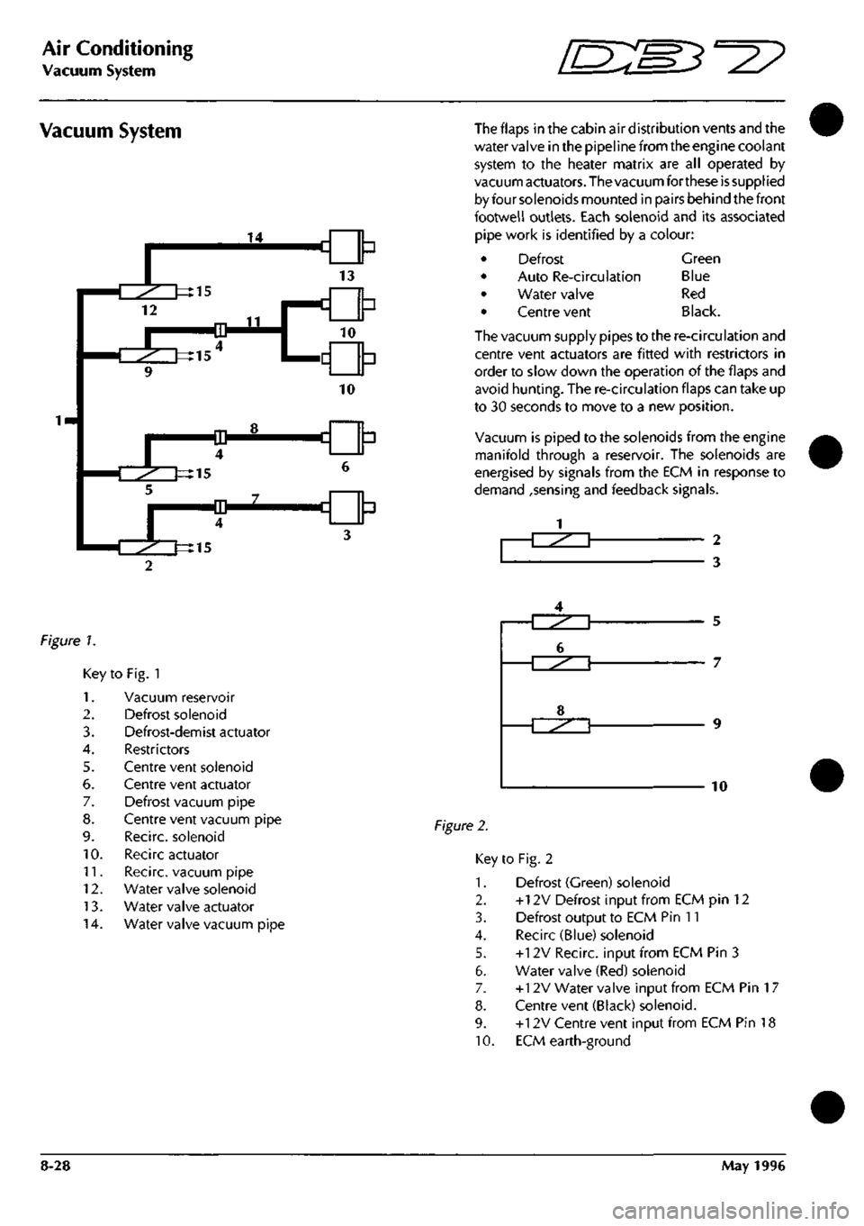
Vacuum System The flaps in the cabin air distribution vents and the
water valve in the pipeline from the engine coolant
system to the heater matrix are all operated by
vacuum actuators. The vacuum forthese
is
supplied
by four solenoids mounted in pairs behind the front
footwell outlets. Each solenoid and its associated
pipe work is identified by a colour:
Defrost
Auto Re-circulation
Water valve
Centre vent
Green
Blue
Red
Black.
The vacuum supply pipes to the re-circulation and
centre vent actuators are fitted with restrictors in
order to slow down the operation of the flaps and
avoid hunting. The re-circulation flaps can take up
to 30 seconds to move to a new position.
Vacuum is piped to the solenoids from the engine
manifold through a reservoir. The solenoids are
energised by signals from the ECM in response to
demand ,sensing and feedback signals.
-T^^^T 2
3
figure 7.
Key
1.
2.
3.
4.
5.
6.
7.
8.
9.
10.
11.
12.
13.
14.
to Fig. 1
Vacuum reservoir
Defrost solenoid
Defrost-demist actuator
Restrictors
Centre vent solenoid
Centre vent actuator
Defrost vacuum pipe
Centre vent vacuum pipe
Recirc. solenoid
Recirc actuator
Recirc. vacuum pipe
Water valve solenoid
Water valve actuator
Water valve vacuum pipe
Figure 2.
5
7
10
Key to Fig. 2
1.
Defrost (Green) solenoid
2.
+12V Defrost Input from ECM pin 12
3. Defrost output to ECM Pin 11
4.
Recirc (Blue) solenoid
5. +12V Recirc. input from ECM Pin 3
6. Water valve (Red) solenoid
7. +12V Water valve input from ECM Pin
1
7
8. Centre vent (Black) solenoid.
9. +12V Centre vent input from ECM Pin 18
10.
ECM earth-ground
8-28 May 1996
Page 319 of 421
Air Conditioning
System Checking with the Manifold Gauge Set [n::S3^^?
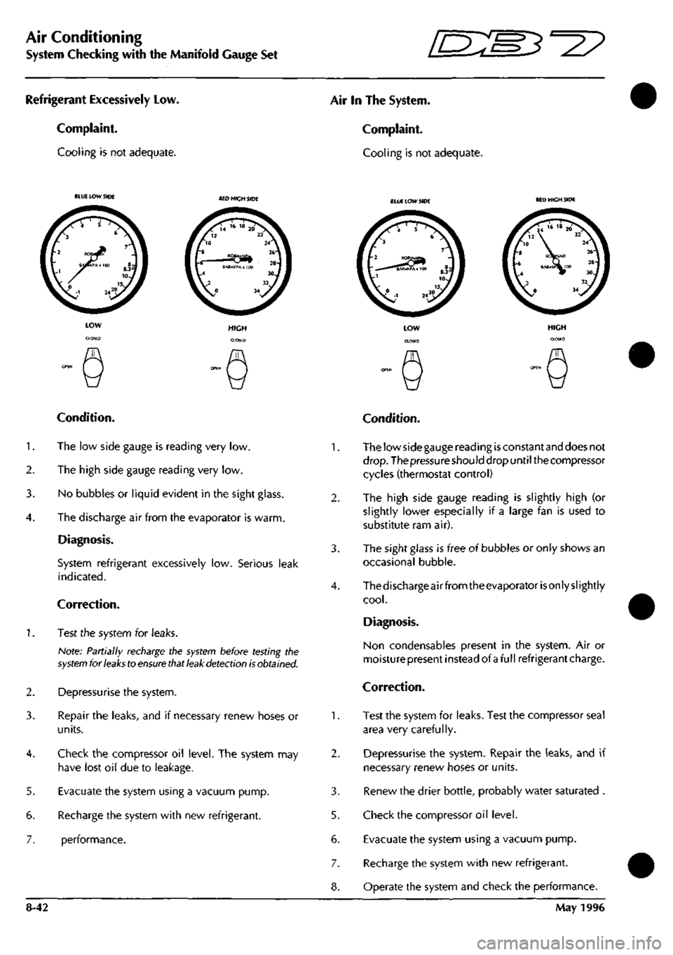
Refrigerant Excessively Low.
Complaint.
Cooling is not adequate.
Air In The System.
Complaint.
Cooling is not adequate.
BLU£ LOW SIDE SlUE LOW SIDE MD HIGH SIDE
5.
6.
7.
Condition.
1.
The low side gauge is reading very low.
2.
The high side gauge reading very low.
3. No bubbles or liquid evident in the sight glass.
4.
The discharge air from the evaporator is warm.
Diagnosis.
System refrigerant excessively low. Serious leak
indicated.
Correction.
1.
Test the system for leaks.
Note: Partially recharge the
system
before testing the
system
for
leaks
to
ensure that leak detection is
obtained.
Depressurise the system.
Repair the leaks, and if necessary renew hoses or
units.
Check the compressor oil level. The system may
have lost oil due to leakage.
Evacuate the system using a vacuum pump.
Recharge the system with new refrigerant.
performance.
2.
3.
5.
6.
7.
8-42
Condition.
The low side gauge reading
is
constant and does not
drop.
The pressure should drop until the compressor
cycles (thermostat control)
The high side gauge reading is slightly high (or
slightly lower especially if a large fan is used to
substitute ram air).
The sight glass is free of bubbles or only shows an
occasional bubble.
Thedischarge air from theevaporator
is
only slightly
cool.
Diagnosis.
Non condensables present in the system. Air or
moisturepresent instead of afullrefrigerantcharge.
Correction.
Test the system for leaks. Test the compressor seal
area very carefully.
Depressurise the system. Repair the leaks, and if
necessary renew hoses or units.
Renew the drier bottle, probably water saturated .
Check the compressor oil level.
Evacuate the system using a vacuum pump.
Recharge the system with new refrigerant.
Operate the system and check the performance.
May 1996
Page 342 of 421
Air Conditioning
Air-Conditioning Diagnostics
The Air Conditioning System Diagnostics
The air-conditioning control module (A/CCM) is located at the right end of the air-conditioning unit.
A
digital microprocessor within the
A/CCM
receives
data
signals from
the
operator controlled
switches.
Comparison
of these signals with those returned from the system temperature sensor and feedback devices results in the
appropriate voltage changes necessary to vary: blower motor
speed,
flap positions and system solenoids to respond
to the drivers selected temperature demand.
The air from the two blower motors is passed through the evaporator matrix which, depending on the A/C mode
selected,
removes heat from the incoming air. Depending on the position of
the
two blend
flaps,
the cold air passes
either directly into the vehicle outlet vents, or is passed through the heater matrix to be reheated and then passed
to the vehicle outlet vents.
The amount of air passing through the heater matrix is infinitely variable depending on ambient temperature and
the temperature selected within the vehicle.
Air Conditioning Diagnostics
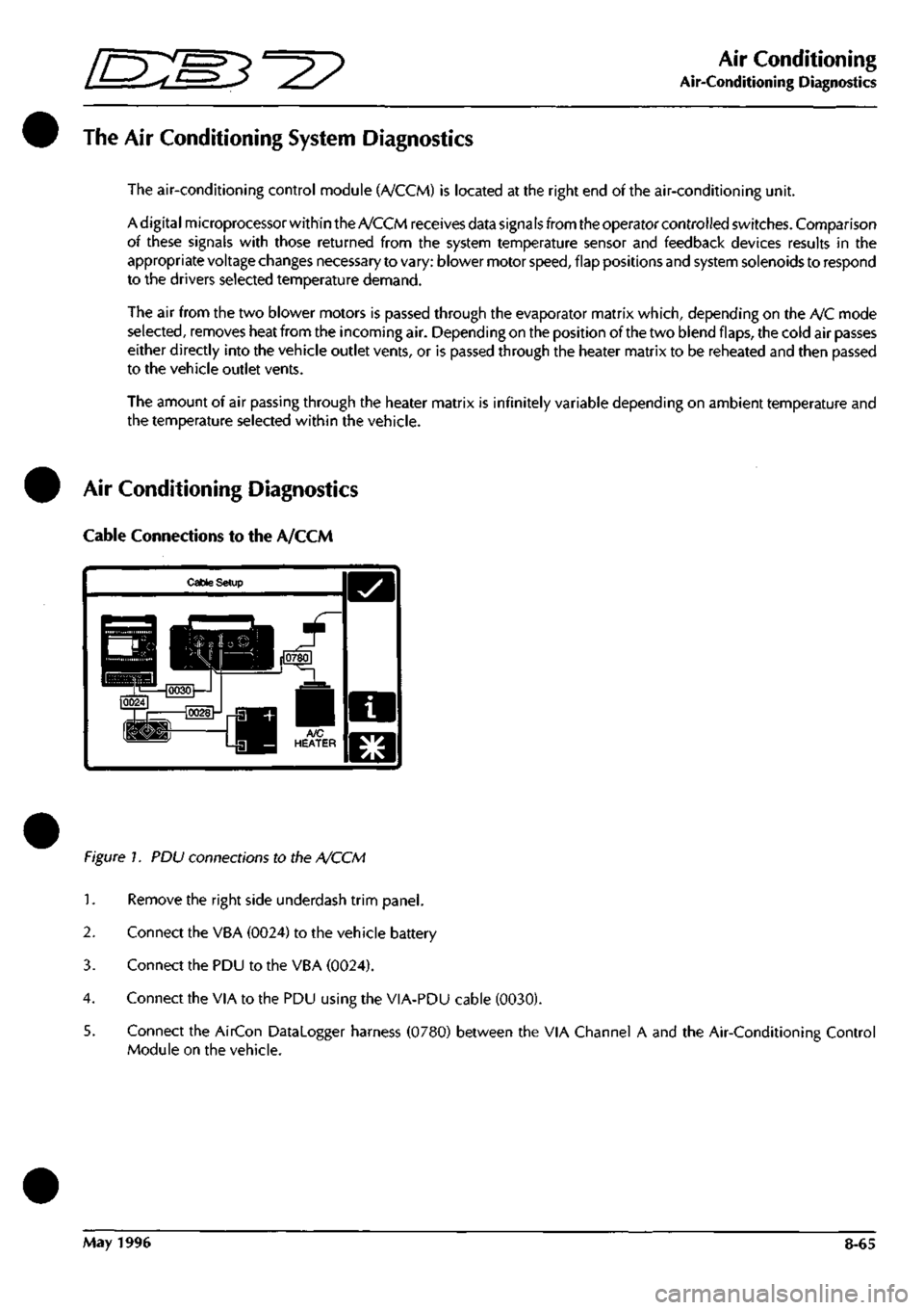
Cable Connections to the A/CCM
Cable Setup
Figure 1. PDU connections to the A/CCM
1.
Remove the right side underdash trim panel.
2.
Connect the VBA (0024) to the vehicle battery
3. Connect the PDU to the VBA (0024).
4.
Connect the VIA to the PDU using the VIA-PDU cable (0030).
5. Connect the AirCon Datalogger harness (0780) between the VIA Channel A and the Air-Conditioning Control
Module on the vehicle.
May 1996 8-65
Page 344 of 421
^=2?
Air Conditioning
Portable Diagnostic Unit - Signal Definitions
ThefollowingsignalsaresupportedontheAir-ConditioningControlModule. For each signal. The signal name, mnemonic
and background information are detailed.
Ambient Temperature Sensor
(AMBTEMP)
Auto-Recircuiation Input
(ARECIP)
Auto-Recirculation Output
(ARECOP)
Auxiliary Battery Positive
(AUX+)
Clutch Relay Drive Output
(CLUREL)
A/CCM Pin 34 ref Pin 6
This sensor is located in the right hand blower motor. This signal is used to enable
the A/C system to compensate for changes in ambient air temperature. The output
to pin 34 is 2.732 volts at 0 degrees Celsius and changes by 0.01 volts for each
degree Celsius above or below zero.
A/CCM Pin 9 ref Pin 6
This is effectively an On/Off switch for the A/C system and forms part of the fan
control switch.
Switch Off - Pin 9 should be at ground
Switch On - Pin 9 should be at 10+ volts.
When pin 9 is at ground, pin 3 will be at 10+ volts causing the recirculation flaps
to open.
A/CCM Pin 3 ref Pin 6
This signal will cause the recirculation flaps to close. Operating conditions should
be:
A/C Off - 10+ volts at pin 3, flaps open.
Temp demand minimum - 10+ volts at pin 3, flaps open.
Defrost - 0 volts at pin 3, flaps closed.
Temp demand max - 0 volts at pin 3, flaps closed.
A/CCM Pin 1 ref Vehicle Battery -ve
This signal istheauxiliary supply to the A/CCM. Pin
1
should read battery voltage
if the ignition switch is in the auxiliary or ignition on positions. Pin
1
should read
0 volts when the ignition switch is in the Off position or in position III whilst
cranking the engine. Loss of this supply will cause total failureof the A/C system.
A/CCM Pin 20 ref Pin 6
This signal responds to the input at pin 5 (evaporator sensor). When pin 5 is
between 2.715 and 2.725 volts, pin 20 should read below 1 volt, and the
compressor clutch will be switched off. When pin 5 is between 2.735 and 2.745
volts,
pin 20 will rise to 10+ volts and the compressor will re-engage.
Centre Vent Solenoid
(CVSOL) A/CCM Pin 18 ref Pin 6
The centre vent solenoid controls the operation of the centre vent flap. The centre
vent will open to increase the cooling capabilities of the vehicle when cooling is
selected.
In all other conditions, the centre vent will be closed.
Solenoid energised: pin 18 should read 10+volts and the centre vent will be open.
Solenoid de-energised; pin 18 should read below 0.5 volts and the centre vent
should be closed.
May 1996 8-67
Page 347 of 421
Air Conditioning
Portable Diagnostic Unit - Signal Definitions ^^P
Ground Voltage
(GND2)
Ground Voltage
(GND38)
Ground Voltage
(GND45)
Ground Voltage
(GND6)
High Speed Relay Drive
(HSREL)
In-Car Sensor
(ICSEN)
A/CCMPin2refPin6
A/CCM Pin 38 ref Pin 6
A/CCM Pin 45 ref Pin 6
A/CCM Pin 6 ref Battery -ve
The four ground signals above must be at battery negative voltage at all times.
A/CCM Pin 16 ref Pin 6
The high speed relay drive signal is used to energise the high speed relay and to
run the blowers at full speed, bypassing the normal fan control circuit. The high
speed relay will be energised whenever Defrost or High speed Fans is selected.
Relay energised, pin 16 should read 10+ volts
Relay de-energised, pin 16 should read below 0.5 volts.
If the signal at pin 16 is correct but only one fan responds, suspect a fault in the
harness or relay.
A/CCM Pin 4 ref Pin 6
The in-car temperature sensor operates in the range 0-5 volts. Actual output is
2.732 volts at 0 degrees Celsius ±0.01 volts for every degree Celsius above or
below zero. The sensor signal forms a reference point for the whole system.
If the signal on this pin remains at less than
1
volt, suspect either a short to ground
on the signal wire or an open circuit on the 5 volt supply line to the sensor.
If the signal rises to approximately 3 volts, then suspect an open circuit on the
ground supply to the sensor.
8-70 May 1996
Page 353 of 421
The Aston Martin Lagonda Diagnostic System
Installation Instructions E:MB^^?
Introduction The Aston Martin Diagnostic System
This guide contains instructions for the installation
of the Portable Diagnostic Unit hardware in Aston
Martin Dealer workshops. To achieve maxinnum
benefit from the system, please follow the
instructions carefully. The following System
Diagram shows the principal system components
and panel details.
This introduction briefly describes the system and
its capabilities. This is followed by the Installation
and Power-Up procedures which give detailed
instruaions on how to start the system and access
the self-contained Interactive
Training
Programme.
The subsequent sections detail the fault diagnosis
and maintenance procedures.
WARNING:
The equipment must
only
be used by
trained
personnel.
Care should
be taken to use the
equipment in accordance with the operating
procedures.
Observe
all safety
warnings
in this
guide.
If any part of
the system is damaged do not
use it. Call your local CenRad
Service
Centre
immediately
for a
substitute
part.
Refer to
'Parts
Ordering'.
The Aston Martin Diagnostic System is a new
generation diagnostic
tool
which fulfils
a
number of
functions in aiding the technician to quickly and
accurately locate faults. The heart of the system is
the Portable Diagnostic
Unit,
a
lightweight powerful
computer/measurement system providing a step-
by-step user friendly interface for the technician.
PDU functions include:
Data Logger - The ability to monitor and record
control module signals even whilst the vehicle is
being driven.
On-Line Help-Containing detailed descriptions in
the
operation
ofthevehicleselectroniccomponents.
Vehicle Setup - The ability to setup various
adjustable parameters to their optimum settings.
Diagnostic Trouble Codes - The ability to extract
recorded fault information from the DB7's control
modules.
Each of
these
funaions is described in detail in the
PDU Users Guide.
WARNING: If
the system is used to measure high
voltages,
these voltages can appear on the pins of
other
connectors in
the
system.
Ensure
that socket
covers
are
fitted
on
unused
sockets.
Ensure
that all
connections
are
made
prior to
applying the high
voltage to
the
probes.
Do not
leave the equipment
unattended
in
this
state.
The maximum
voltage
that may be applied
between the
test
probes is 150
volts
AC or DC.
Radio Interference Statements
This digital apparatus does not exceed the Class A
limits for radio noiseemissionsfromdigital apparatus
as set
out
in
the radio interference regulations of the
Canadian Department of Communications.
This equipment has been tested and found to
comply with the limits for Class A digital device
pursuant to part 15 of the Federal Communications
Commission (FCC) rules. However, operation in
close proximity to domestic communication
equipment may cause interference. It is the
responsibility of the user to avoid or correct this
condition.
9-2 May 1996
Page 366 of 421

r^ ' ^ ^ The Aston Martin Lagonda Diagnostic System
Installation Instructions
Finishing the Test
When data analysis is finished, switch off the PDU
and disconnect it from the vehicle. Store the PDU
and cables in the carrying case and refit the case to
the base station.
Connect the PDU to the base station using cable
0064.
The base station will keep the PDU batteries
fully charged at all times (Fig 15).
Figure 15. PDU connected for recharging
Care of the Equipment
CAUTION: With the exception of those parts
referred to in the Servicing and Maintenance
section, there are no user serviceable parts. All
servicing must be carried out by GenRad Service
Centres.
Switch offthe power before cleaningtheequipment.
The Aston Martin Diagnostic System should only
be cleaned using a non-abrasive, mild cleaning
agent. Dust and other particles should be lightly
brushed from the surface before
cleaning.
Cleaning
agent should be applied to a soft lint-free cleaning
cloth and never directly to the unit. Do not soak the
cleaning cloth and take care not to allow cleaning
fluid to enter connectors.
CAUTION: Ifany liquid is spilt on theequipment,
switch off immediately.
Ensure
that the equipment
has
dried out completely before operating it again,
especially in connectors where fluid can lodge.
May 1996 9-15
Page 369 of 421
The Aston Martin Lagonda Diagnostic System
Installation Instructions -=2?
Step 11
Adjust the contrast control. Is the PDU touch screen illuminated?
YES - Co to step 12
NO - Renew the PDU (0017)
Step 12
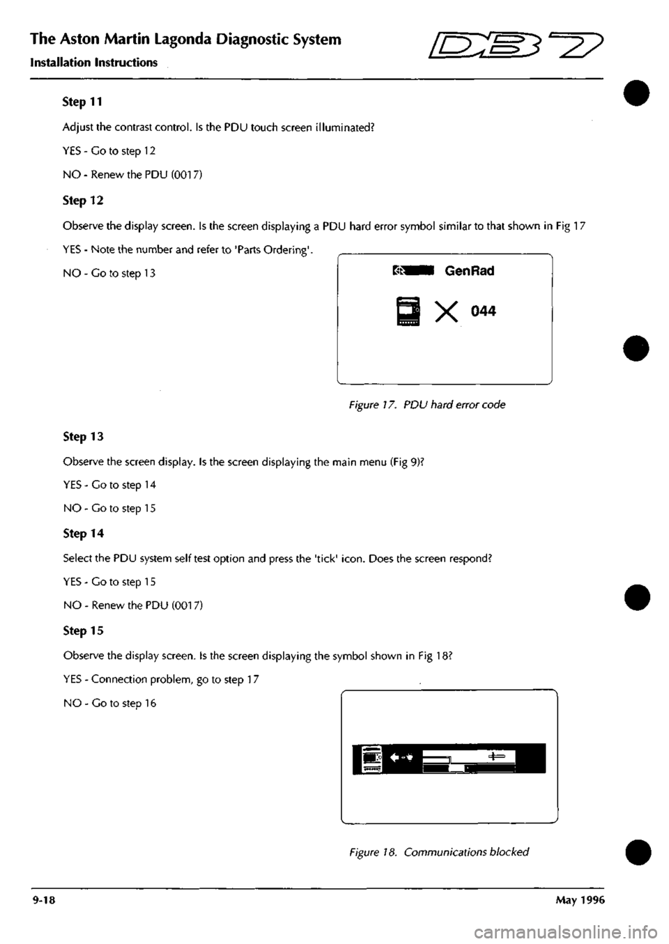
Observe the display screen. Is the screen displaying a PDU hard error symbol similar to that shown in Fig 17
YES - Note the number and refer to 'Parts Ordering'.
NO - Co to step 13
Figure 17. PDU hard error code
Step 13
Observe the screen display. Is the screen displaying the main menu (Fig 9)?
YES-Co to step 14
NO - Go to step 15
Step 14
Select the PDU system self test option and press the 'tick'
icon.
Does the screen respond?
YES - Co to step 15
NO - Renew the PDU (001 7)
Step 15
Observe the display screen. Is the screen displaying the symbol shown in Fig 18?
YES - Connection problem, go to step 17
NO - Co to step 16
Figure 18. Communications blocked
9-18 May 1996
Page 394 of 421
^?
The Aston Martin Lagonda Diagnostic System
Users Guide
Climate Control Diagnostics
The air conditioning control module is located at the right
end of the air conditioning unit. Since this controller uses
a unique communications protocol, the PDU must be
connected directly to the unit via the Vehicle Inerface
Adaptor as shown in the following cable setup screen.
Cable Setup
Adigitalmicroprocessorwithin the control module receives
data signals from the operator controlled switches.
Comparison of these signals with those returned from
system temperature sensors and feedback devices results
in the appropriate output voltage changes needed to vary:
Blower motor speed, flap position and the solenoids
which respond to operator selected temperature demand.
The air from two blower motors is passed through the
evaporator matrix which, depending on the positions of
the humidity buttons, removes heat from the incoming air.
Dependingon the position of the two blend flaps, the cold
air either passes directly to the vehicle outlet vents, or is
passed through the heater matrix to be reheated and then
to the vehicle outlet vents.
The amount of air passing through the heater matrix is
infinitely variable depending on ambienttemperature and
the temperature selected within the vehicle.
Selecting 'Climate Control' from the vehicle area menu,
will presentthetechnician with the dataloggertool selection
screen.
Details of the signals which may be monitored in the
system may be found in the DB7 Workshop Manual -
Section 8 - Air Conditioning'
Anti-Lock Braking Diagnostics
The Teves Mk IV Braking System consists of two sub
systems, power braking and anti-lock braking.
The PDU software(DataLogger) only allows the monitoring
of the anti-lock braking system.
The ABS System consists of:
Four wheel speed sensors.
One control module.
Seven solenoid valves.
One pressure switch.
One fluid level switch.
The ABS System
is
controlled and continuously monitored
by the ABS control module, which automatically
switchesoffthesystemifafailure is identified, illuminating
a warning lamp and leaving
full,
boosted braking to all
wheels. A wheel speed sensor is installed at each wheel.
Their wheel speed related signals are processed by the
control module, which triggers the solenoid valves to
modulate hydraulic pressure, preventing the wheels from
locking.
The control module also monitors the fluid
level and will inhibit ABS operation should lowfluid level
be detected.
The Datalogger function will permit monitoring of the
complete system apart from the solenoid valves. The
control module transmits short duration test pulses of 25
to 100 microseconds to the solenoid valves. These
pulses are too fast for the PDU to monitor and as a result
would cause confusing waveforms.
Selecting 'Anti-Lock Braking' from the vehicle area menu,
will present the technician with the following menu of
diagnostic tools screen:
Anti-Lock Brakes Diagnostic
Datalogger
Diagnostic Trouble Codes
o
ABS Diagnostic Trouble Codes
The DTCs which are supported in the Teves Mk IV ABS
system are listed in the workshop manual - Section 5
Brakes Wheels and Tyres.
September 1996 9-43
Page 398 of 421
^^?
The Aston Martin Lagonda Diagnostic System
Users Guide
Seat Belt Pretensioner Diagnostics
(where fitted)
Description
The DB7 seat belt pretensioner system operates the
drivers seat belt pretensioner in conjunction with the
Airbag system. The seat belt pretensioner control
module is located underthe right hand seat, beside the
seat control module.
The pretensioner control module calculates changes
in vehicle speed using an input signal from an
accelerometer. When a collision is detected (Rapid
reduction in vehicle speed) the pretensioner charge is
fired using electrical energy stored in a capacitor
within the pretensioner control module. Firing of the
pretensioner charge applies additional tension to the
drivers seat belt.
The airbag and seat belt pretensioner systems share the
SRS (Airbag) warning lamp. Any fault detected by the
pretensioner control module is indicated by constant
illumination ofthe
SRS
(Airbag) warning
lamp.
Flashing
of the SRS warning lamp indicates a fault in the airbag
system.
Should both systems develop faults, the pretensioner
system will permanently illuminate the warning lamp.
This would mask the airbag system warning indication.
Therefore, rectify the pretensioner fault and then retest
for faults in the airbag system
The pretensioner control module can log up to 10
diagnostic trouble codes together with a time since
each fault was alerted to the driver. Each fault will be
identified as 'Permanent' or 'Intermittent' on the PDU
diagnostic trouble codes screen.
System Connections
The Autoliv RC5 Pretensioner Control Module has an
18 pin connector featuring six shorting bridges. The
mating halves ofthe connector may be securely locked
using a double mechanical locking system.
The following pins on the control module connector
are used in the Aston Martin seat belt pretensioner
system:
Pin 1
Pin 2
Pin n
Pin 12
Pin 14
Pin 15
Case
September 1996
Ground
SRS/Airbag Warning Lamp
Drivers airbag positive
Drivers airbag negative
Serial communications
12 volt positive feed
Ground
System Fault Strategy
No single fault may cause an unexpected deployment.
The controller will supervise the airbag/pretensioner
electrical system in order to warn the driver should a
fault occur. Any fault detected by the self diagnostics
shall cause the airbag warning lamp to be activated,
and in some cases the pretensioner control module to
enter shutdown mode. In shutdown mode, the energy
ofthe reserve capacitors shall be discharged to avoid
unintended deployment.
As the ignition is switched on, the pretensioner
controller will directly discharge theenergy capacitors.
When the start up procedure is completed without
detecting any faults, the converter will be activated
allowing the capacitors to be
charged.
The system shall
be fully active within 11 seconds after switching the
ignition on providing that no faults are detected.
All system faults monitored by the controller are filtered
in software to avoid fault warnings due to transient
electrical disturbances.
If a fault which could lead to inadvertent deployment
bedetectedbythemicroprocessor,asoftwareshutdown
will be generated. However, a leakage to an earth or
positive potential in the pretensioner output circuit
shall not cause the controller to enter shutdown mode.
If
a
permanent short of the ignition transistor occurs, a
shutdown shall be generated by the hardware circuit.
If a shutdown occurs, the system shall be unable to
deploy the pretensioner after a period of
3
seconds (i.e.
capacitors discharged to under minimum deployment
voltage).
WARNING: To avoid the possibility of personal
injury caused by accidental deployment of the
pretensioner, disconnect the vehicle battery and
wait at least 10 minutes for all voltages to fully
discharge before working on the pretensioner
system. This covers the possibility of the normal
capacitor discharge circuits being inopera tive and
failing to discharge the capacitor when instructed
to do so.
If the module enters shutdown mode, all diagnostic
functions are stopped, but the communications link
remains active. A fault code corresponding to the
cause of the problem may be read by the PDU.
9-47