gearbox ASTON MARTIN DB7 1997 User Guide
[x] Cancel search | Manufacturer: ASTON MARTIN, Model Year: 1997, Model line: DB7, Model: ASTON MARTIN DB7 1997Pages: 421, PDF Size: 9.31 MB
Page 129 of 421
Electrics
Relay Location Index - 97 MY 5^^?
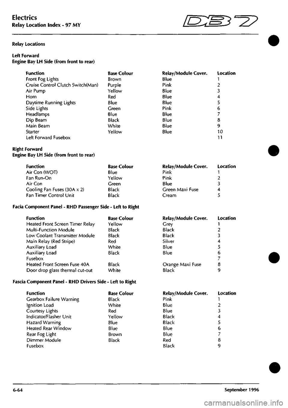
Relay Locations
Left Forward
Engine Bay LH Side (from front to
Function
Front Fog Lights
rear)
Cruise Control Clutch Switch(Man)
Air Pump
Horn
Daytime Running Lights
Side Lights
Headlamps
Dip Beam
Main Beam
Starter
Left Forward Fusebox
Base Colour
Brown
Purple
Yellow
Red
Blue
Green
Blue
Black
White
Yellow
Relay/Module Cover.
Blue
Pink
Blue
Blue
Blue
Pink
Blue
Blue
Blue
Blue
Location
1
2
3
4
5
6
7
8
9
10
11
Right Forward
Engine Bay LH Side (from front to rear)
Function Base Colour
Air Con (WOT) Blue
Fan Run-On Yellow
Air Con Green
Cooling Fan Fuses (30A x 2) Black
Fan Timer Control Unit Black
Facia Component Panel - RHD Passenger Side - Left to Right
Function Base Colour
Heated Front Screen Timer Relay Yellow
Multi-Function Module Black
Low Coolant Transmitter Module Black
Main Relay (Red Stripe) Red
Auxiliary Load White
Auxiliary Load Black
Fusebox
Heated Front Screen Fuse 40A Black
Door drop glass thermal cut-out White
Fascia Component Panel - RHD Drivers Side - Left to Right
Function
Gearbox Failure Warning
Ignition Load
Courtesy Lights
Indicator/Flasher Unit
Hazard Warning
Heated Rear Window
Rear Fog Light
Dimmer Module
Fusebox
Base Colour
Black
White
Red
Yellow
Blue
Blue
Brown
Black
Relay/Module
Pink
Pink
Blue
Cover.
Green Maxi Fuse
Cream
Relay/Module
Grey
Black
Black
Silver
Blue
Blue
Cover.
Orange Maxi Fuse
Black
Relay/Module
Pink
Blue
Blue
Black
Black
Blue
Blue
Red
Black
Cover.
Location
1
2
3
4
5
Location
1
2
3
4
5
6
7
8
9
Location
1
2
3
4
5
6
7
8
9
6-64 September 1996
Page 131 of 421
Electrics
Relay Location Index - 97 MY
D^^
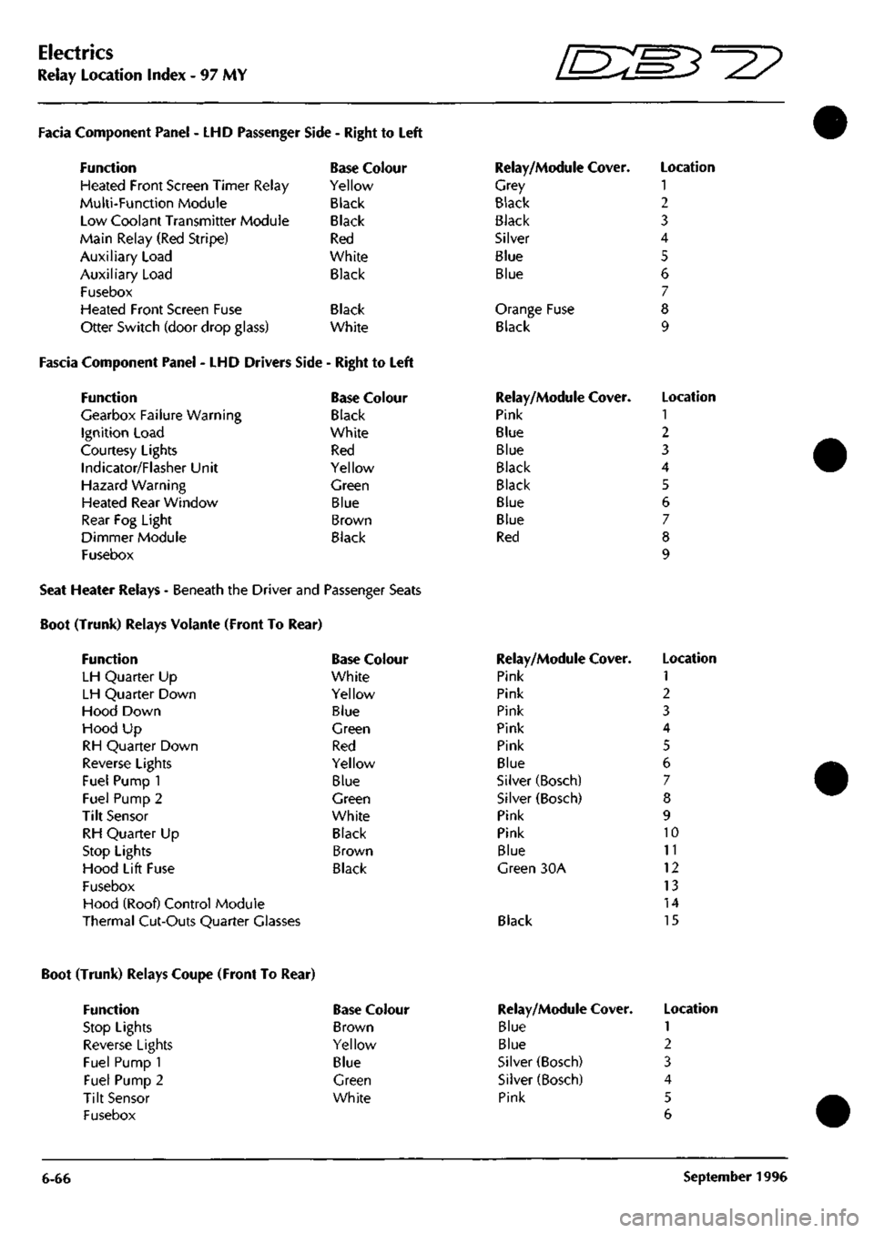
Facia Component Panel
- LHD
Passenger
Function
Heated Front Screen Timer Relay
Multi-Function Module
Low Coolant Transmitter Module
Main Relay (Red Stripe)
Auxiliary Load
Auxiliary Load
Fusebox
Heated Front Screen Fuse
Otter Switch (door drop glass)
Side
-
Right
to
Left
Base Colour
Yellow
Black
Black
Red
White
Black
Black
White
Fascia Component Panel
- LHD
Drivers Side
-
Right
to
Left
Function
Gearbox Failure Warning
Ignition Load
Courtesy Lights
Indicator/Flasher Unit
Hazard Warning
Heated Rear Window
Rear
Fog
Light
Dimmer Module
Fusebox
Base Colour
Black
White
Red
Yellow
Green
Blue
Brown
Black
Relay/Module Cover.
Grey
Black
Black
Silver
Blue
Blue
Orange Fuse
Black
Relay/Module Cover.
Pink
Blue
Blue
Black
Black
Blue
Blue
Red
Location
1
2
3
4
5
6
7
8
9
Location
1
2
3
4
5
6
7
8
9
Seat Heater Relays - Beneath the Driver and Passenger Seats
Boot (Trunk) Relays Volante (Front To Rear)
Function
LH Quarter
Up
LH Quarter Down
Hood Down
Hood
Up
RH Quarter Down
Reverse Lights
Fuel Pump
1
Fuel Pump
2
Tilt Sensor
RH Quarter
Up
Stop Lights
Hood Lift Fuse
Fusebox
Hood (Roof) Control Module
Thermal Cut-Outs Quarter Glasses
Base Colour
White
Yellow
Blue
Green
Red
Yellow
Blue
Green
White
Black
Brown
Black
Relay/Module Cover.
Pink
Pink
Pink
Pink
Pink
Blue
Silver (Bosch)
Silver (Bosch)
Pink
Pink
Blue
Green
30A
Black
Location
1
2
3
4
5
6
7
8
9
10
11
12
13
14
15
Boot (Trunk) Relays Coupe (Front To Rear)
Function
Stop Lights
Reverse Lights
Fuel Pump 1
Fuel Pump 2
Tilt Sensor
Fusebox
Base Colour
Brown
Yellow
Blue
Green
White
6-66
Relay/Module
Blue
Blue
Silver (Bosch)
Silver (Bosch)
Pink
Cover. Location
1
2
3
4
5
6
September
1996
Page 140 of 421

NO COLOUR 200 RP 201 RG 197 BK 202 8 190 RK
PIN 1 2 3 A
I
AREA 4.Be •1.C5 4.BI
4.B4-30
Bl
HO COLOUR
PIN
AREA 205 GU
I
4B3-29
204 CP 2 4.C5
205
WU
3 4.C5
PERFORMANCE MODE SWITCH BAROMETRIC PRESSURE SENSOR
lyyyygyl
V3
NO COLOUI 182 S
184 0 185 m 186 B 187 BU 188 G 189 SP 190 RK 191 GB 192 V» 193 KB 194 YG 195 GP 196 KU 197 BK 198 RN 199 K
PIN 1 ? 3 4 5 6 7 e 9 10 n 1? 13 14 15 16 17 IB 19 20
AREA 4.B5
4.B5 4.B5
4.B4-30
4.B5 4.D2 4.B5 4.A2 4.B5 4.B6 4.B5 4.B5 4.B6
4
B5 4.A2 4.B5 4.B5
[|
r
1 20 T •T]
D D D D D D( D ^
a D' D D D D| D ^ D D' D D D D
^
^m.
ENGINE HARNESS
V
V
SHEET 7 AREA Al
GEARBOX LINK HARNESS
NO COLOUf 206
OW
207
OR
IBB G 208
OP
209
OB
210 OS 211 OK 212 ON 213 OU 214 OY 215 GU 216 R 217 U 216 G 219 N
PIN 1 2 3 4 5 6 / B 9 10 II 1? 13 14 15 16 17 18 19 20
AREA 4.B5 4.B5 4.BI 4.B5 4.B5 4.B5 4.B5 4.B6 4.B6 4.86
4.83-29
4.86 4.B5 4.85 4.86
NO COLOUR
207
OR
182 S 191 GS 206
OW
208
OP
196 KU 184 0
PIN 38 39 40 41 4? 43 44 45 46
AREA
4.02 4.81 4.81 4.D2 4.D2 4.61 4.81
NO COLOUR
210 OS 218 G 217 U 209 08 193 KB 222 8 185 NR
PIN 47 48 49 50 51 52 53 54 55
AREA
4.02 4.02 4.02 4.02 4.81
4.84-30
4.BI
f OOOC yoooc K>OOQ'
GEARBOX E.C.U
NO COLOUR
I9B
RN
211
OK
213
OU
201
RG
220 B 194
YG
PIN
? 3 4 5 6
7 8 9 10
AREA
4.81 4.02 4.02 4.A2 4.B4-30 4.81
NO COLOUF 187
BU
169
SP
221
GU
204 GP 199
K
205 WU
PIN II
12 13
14 li 16
17 IB 19
AREA 4.81 4.81
4.B3-29 4.A4 4.BI 4.A4
NO COLOUR
212 ON
200 RP
195
CP
214
OY
192
W
216
R
219
N
PIN 20 ?l
??
23 ?4
?5
26 27 28 79 30 31 32 33 34 35
36 37
AREA
4.02 4.A2
4.81 4.02
4.81
4.02 4.D2
°27 Wiring Diagram
Model - Aston Martin DB7
Harness Title - Auto Transmission
Drawing Part No. - B3
7-84629
Revision - 0 Sheet 4 of 26 - 97 MY
Page 146 of 421

gn
NO COLOUR 206
OW
207
OR
ISS G 208
OP
210 08 210 OS 211 OK 212 ON 213 OU 214 OV 215 BU 216 R 217 U 218 G 219 N
PIN 1 2 3 4 5 6 7 8 9 10 II 12 13 14 IS 16 17 18 19 20
4RE4 7.A5 7.*5
7.42-220
7.45 7.45 7.45 7.45 7.45 7.45 7.45 7.45 7.45 7.45 7.45 7.45
4—« SHEET 4 AREA C3
GEARBOX CONNECTOR
M
Q HI Q
OUTPUT SPEED SENSOR
NO COLOUR PIN 216 R I
217
U 2
4RE4 7.41 7.41 INPUT SPEED SENSOR
NO COLOUR PIN 219 N I 218 C 2
4REA 7.41 7.41
NO COLOUR 207 OR 208 OP 2187 *H 211 OK 212 ON 213 OU 214 OV 215 BU 206 OW 2188 WR 209 08
210 OS
PIH 1 2 3 4 5 6 7 8 9 10 II 12 13 14
4REA 7.41 7.41
7.42-220
7.41 7.41 7.41 7.41 7.41 7.41
7.42-220
7,41
7.AI
NO COLOUR 830 8G 803
SLG
123 YU 831 YR
835
B
836 8G 831 YR 123 YU
PIN 1 2 3 4 5 6 7 8 9 10 fl 12 13
4RE4 7.C2 7.C5 7.CI 7.CI
C5 C2 7.CI 7. CI
123.830.831,836 TAPED IN LOOM
REVERSE LAMP SWITCH
I NO COLOUR PIN
ARET
1
803 SLG I 835 6 7.CI 7.CI
in::My^2? wiring Diagram
Model - Aston Martin DB7
Harness Title - Auto/Manual Transmission
Part No. - B37-84632
Revision - 0 Sheet 7 of 26 - 97 MY
Page 150 of 421
COLUMN SWITCHGEAR NO COLOUR
PIN
670
B
671
BK
572
NR
71
NB
673
U
80
UW
674
GW
615
G
675
GR
676
LOR
677
LC
678
LGP
679 BP 680 LGN 681
LGW
G82
0
683 LOG 139
WU
58
PB
137
NU
1 7. 3 1 5 6 7 8 9 10 II 1? 1} 14 15 16 17 18 19 20
AREA
8.B4-67
I0.B2-9:
8.65-70
8.AI 9.A2 S.AI I0.B2-9I 8.C3
8.C2-79
II.B6 IO.BI-89 ILB6
9.83-81
II.B6
ii.Be
II.B4-I2I II.B6 8.CI 8.BI 8.BI
COURTESY LIGHT
ID
NO COLOUR PIN 684
PG
1 685
B
2 686 PW 3 687 P 4
AREA
8.B2-6I
8.B2-G2
9.01
8.B5-7I
SHEET 8 AREA B6
2K2 RESISTOR NO COLOUR PIN 692
U
A 673
U
6
AREA
9.83-83
9.AI 'AAAA-
lOL
ID]
(D
CRUISE DISABLE
8
STOP LAMP SWITCHES
[=r
NO COLOUR
PIN 693 8 I 694 LGY 2 127 YR 3 695
CB
4
AREA
8.B4-67
9.B5-82
8.BI IO.C3-I0I
DRIVERS AIRBAC
NO COLOUR
PIN 696 RP I 2 697
KN
3
AREA
II.C4-I20
NO COLOUR PIN AREA 688 U U
9.C2-76
689
U W
9.C5-86
NO COLOUR
PIN
690 RY
U
691
U W
AREA
9.C2-78
9.C5-86
^=^^1
[^1
SPL
77 SPL 79
I
I
INSTRUMENT PACK GREEN I T ,.
NO COLOUF 268 NB 726 RB 134 UW 727 GR 707 SW 196 KU 729 PS 264 OS 238 OK 752 LOO 733 W¥ 192 WS 325 WS 736 RIN 737 UIN 738 BRD
PIH 1 ? 3 4 5 6 7 8 9 10 II 12 13 14 15 16
AREA
12.
Al lO.CI 8.BI
9.C2-79
9.02 II.CI 1I.C3 I2.AI I2.AI
10.B2-97
9.B5-87
II.CI I2.A2 I0.C5 I0.C5 I2.C5-I03
INSTRUMENT PACK BLACK
-
SPL
83
-SPL
82
-SPL
81
NO COLOUR
PIN
AREA
720
GN
U
9.C4-85 721
OR W
9.C2-79
|F^
SPL
76 SPL 78
P.A.T.S. TRANSCEIVER DIMMER SWITCH
n
n/J D D II 11 II 11 II 11 D D II
1 1
u ul|,
NO COLOUf 739 BS 740 YW
741 GN 742 GW 743 GO 744 WU 745 BW 328 UG 747 BY
191 GB 611 OU 749 OU 610 OS 750 OS
PIN 1 2 3 4 5 6 7 8 9 10 II 12 13 14 15 16
AREA II.B3-I16 IO.B2-92
9.C4-85
I0.B2-9I I2.A5 I2.B2
I0.B2-9'
I2.AI
9.A5-88
ILBI 8.03 I2.DE 8.03 12.06
INSTRUMENT PACK WHITE
D D D D
CB D D D D • D
^
Tl
NO COLOUf 751
WK
752
P
753
GR
754
GY
755
B
756
B
757
RW
758
GU
759
GN
PIN 1
2 3
4
5 6 7 8 9
10 II 12
AREA
8.B5-73
1I.B4-I22
9.C6 9.C6
8.B4-67
8.B2-63
8.B4-68
9.C6 9.C6
DIAGNOSTIC SOCKET
NATURAL BASE
J¥tL
87A 87A
nifl
NO COLOUR
PIN
709
W
1
710
B 2
7H
UW 3
712
OB 4
AREA I2.BI I2.BI
I2BI I2.BI
BLACK BASE
COURTESY HO COLOUR 698 6U 699 P 700
PW
686
PW
LIGHT RELAY PIN AREA 85 I1.B4-I27 86
8.B5-7I
87
8.83-65
87A 30 9.BI
AUX LOAD RELAY NO COLOUR 701 B 702
WK
703
WO
704
N
PIN 85 86 8/ 87A 30
AREA
8.B2-62
9.C2-77
8.B5-72
I0.A2
GEARBOX WARNING NO COLOUR 182
S
706
WK
"
707 SW 708
WK
PIN AREA 85 II.BI 86
8.85-73
87
87A
9.A4
30
8.B5-73
l>°
l>«'
l>»'
ll">'
l>-'
l>='
'
6
NO COLOUR PIN 1 2 3 629
K
4 627 0 5 628 R 6
AREA
8.C5 8.C5 8.C5
NO COLOUR PIN 753
GR
1 754 OY 2 758
GU
3 759
GN
4
AREA 9.B6 9.66 9.B6 9.B6
KEY SOLENOID KEY-IN WARNING SWITCH NO COLOUR PIN AREA
713
YN I 1LC3
714
YB 2
II.C3
NO COLOUR
PIN
AREA 715
PG I 12.A5
716
a 2
8.62-63
GNITION SWITCH NO COLOUR
717 718 84 719
N WK WY W
PIN 1 ? 3 4
AREA I0.A2
9.C2-77
8.AI
8.66-74
"^3? wiring Diagram
Model - Aston Martin DB7
Harness Title - Bulkhead LHD - 2
Part No. - 837-84634
Revision - 0 Sheet 9 of 26 - 97 MY
Page 154 of 421
NO COLOUF 890 N 891
NK
892 N 893 P 894 N 895 NW 896 N 131
NS
897 N 898 P 88SN 899 NP 900 W 339 WR 901
W
902
0
903 WK 904 OW 905
W
188
G
906 N 907 PN
PIN 1 ? 3 4 S 6 7 8 9 10 II 1? 13 14 15 16 17 18 19 ?0 21 22
AREA II.A5-I24 I2.C6 II.A5-I25 IZ.C2-I39 II.A5-126 I2.C3 11.45-125 I2.A4 II.A5-I26
e.B5-7l
II.A6 I2.D2 I2.CI~I29 12.81 I2.CH29 II.B4-I2I II.B5-I28 12.06 I2.CI-I29 II.BI II.A5-I24 1I.B2-II3
25JL25n 27n 29n 3in 33n 35n 37n 39n ''ia,''3rL
24V26V28V3oV,2*34V3sV38V4oV42V44V
NO COLOUF 908 N 909 NG 910
KB
193
KB
911
W
834 G 912
WK 770 10
913
WK
820
0?
914
W
865 LGS 915
N
870 RW 916
KB
297 NS 917
N
918
P
919
N
185
NR
888 N 766 NO
PIN ?3 ?4 25 ?6 27 28 29 30 31 3? 33 34 35 36 37 38 39 40 41 4? 43 44
AREA II.A5-I26 I2.C6 I2.C2-I32 II.CI I2.CI-I29 II.B3 II.B5-I28 II.CI II.B5-I28 11.01 12.01-129 II.B3~II8 II.B4-I23 II.C6 I2.C2-I3; I2.A1 II.A5-I24 II.B4-I22 II.B4-I23 11.81 II.Ae lO.CI
SPL
124 SPL 125 SPL 126
SHEET 10 AREA B6 iF^^i
-«-
SHEET
t
AREA
Bl
GEARBOX
RED
NO COLOUF 182
S
184
0
185
NR
186
BY
187
BU
188
G
189
SP
190
RK
191
GB
192
WS
193
KB
194
YG
195
GP
196
KU
197
BK
198
UN
199
K
PIN
1 2 3
4 5 6 / 8 9 10 II 1? 13 14 15 16 17
18 19 20
AREA 9.D2
I0.B3-III II.A3 12.A3 I2.A3 II.AI I2.A3 10.B2-93 9.A6 9.B4 II.A3 I2.A3 1I.C2-II5 9.A4 10,85-105 I2.A3 I0.A3
AIR CON UNIT
NO COLOUR
PIN
768
B
?70
LG
163
GN
780
W
782
PN
783 RW 784 R
1 2 3 4 5 6
7 8 9 10 II 12
AREA 12.03-143 II.A3 I2.A4 12.01-129 II.B2-II3 II.B2-II4 I0.B4-84
NO COLOUF 817
YO
818
RG
819
OR
379
RU
380
GU
820
GP
821
RW
121
Y
825
BP
731
U
2200
LGY
332
B
PIN 1 2 3 4 5 6 7 8 9 10
II 12 13 14 15 16
AREA 11.03 12.02-134 12.06 I0.B4-I0a 8.DI II.A3 II.B2-II4 8.AI
9.B3-8I
9.B3-83
9.B3-82
12.03-143
<^
• SHEET 13 •AREA B6
NO COLOUR
PIN
AREA 876
RU U
IO.B4-10S 877
RG
W -
I2.BI-I30 SPL
123
-
SPL
122
-
SPL 121
-
SPL
117
SPL
118
c
AUTO
G/BOX HARNESS
SHEET
7 v^ r-
AREA
CI -** »"
cx
NO OOLOUF 830 BG 803 SLG 123
GP
831
GP
832
GB
833 PH 834
0
713
YN
714
YB
835
B
836 BG 52
GP 49 GP
PIN 1 2 3 4 5 6 7 8 9 10 11 12 13
AREA lO.BS-IOt 10.04 S.BI ILC2-II5 I0.C2-I0I 11.02-113 II.A3 9.03 9.03 I2.C2-I30 I2.AI
8.AI 8.AI
CO]
01
EXHAUST
TEMP/
SPEED WARNING
NO COLOUR 837
B
729
PS
838 PS 839
WP
840 WY 841
W
PIN 1 2 3 4 5 6
AREA 12.02-131 9.A4 12.A5 I2.A5
9.B5-87
I2.BI-129 PASSENGER AIRBAG
BINNACLE
I
(=3;
era
ra
i(=r
NO OOLOUF 842
KB
843 BK 600 PR 844 U 620
Y
845 RK 47
RO
646 PN e47LG 824 SR 848 BU 649 RW 850
B
826 SW 851
BY
852 NY 853 RN 854
WB
617
R
855
U
856 BP 857
LGY
817
YO
PIN 1 ? 3 4 5 6 / 8 9 10 11 12 13 14 15 16 17 18 19 20 21 22 23 24
AREA I2.A1
I0.B5-I0!
8.A3
9.05-86
8.04 I0.B2-93 8.BI II.B2-II3
e.B5-69
10.05 II.B4-I27 II.B2-I14 12.02-131 10.05 12.02 12.03-144
I0.B5-10;
I2.A5 8.03
9.B3-83
9.B3-8I
9.B3-82
11.01
SPL
127 SPL 128
c
IcX
|[=r
NO COLOUR
PIN
AREA 858
RP I
11.04-120 2 859 KP
3 11.06
I BATTERY
~| STUD
NO COLOUI 881
N
882 N 883 N 884
N
885
N
886 N 667
N
886 N
AREA II.A5-I24 II.A5-I26 II.A6 I2.CI ILAI I1.A5-I25 II.B4-I23 I1.B3
CB CD NO COLOUR PIN 883 N I 869 N 2
AREA II.A6 I2.D3
WIPER LOGIC NO COLOUF 874
B
875 0 683 LGG 681 LGW 680 LGN 285
BLG
287
WLG
286
BR
145 LGB
678 LGP 879 LC 676 LGR 880 BS
PIN 1 2 i 4 b 6 7 8 9 10 II 12 13 14 15 16
MODULE AREA I2.C4 II.B4-I2I 9.AI 9.AI 9.AI 12.B3 12.B3 12.B3 12.A4
9.AI IO.Bl-89 9.AI 1I.B2-II6
AIRBAG DIAGNOSTIC MONITOR GREY NO COLOUR 865 LGS 866 ON 867 B 868 YW 869 B 367 YU 870
RW
871 RN 672
RG
873
KU
368 KG
PIN 1 2 3 4 5 6 7 8 9 10 II 12
AREA 11.03-118 12.A6 11.04-119 10.82-92 11.04-119 8.CI II.A3
12.85 12.85
12.
A6 8.CI
AIRBAG DIAGNOSTIC MONITOR BLACK NO COLOUR
860 RP 859 KP 697 KN
861
RP
862
YG
863 OP 369 OW
864
YP
PIN
2 3 4 5 S 7 8 9 10 11 12
AREA
I1.C4-120 II.D4 9.B2 ILC4-I20 12.B5
I2.B6
e.oi
I2.B5
""^^ Wiring Diagram
Model - Aston Martin DB7
Harness Title - Bulkhead LHD - 4
Part No. - B37-84636
Revision - 0 Sheet 11 of 26-97 MY
Page 264 of 421
5^^
Body and Trim
Roof Control System
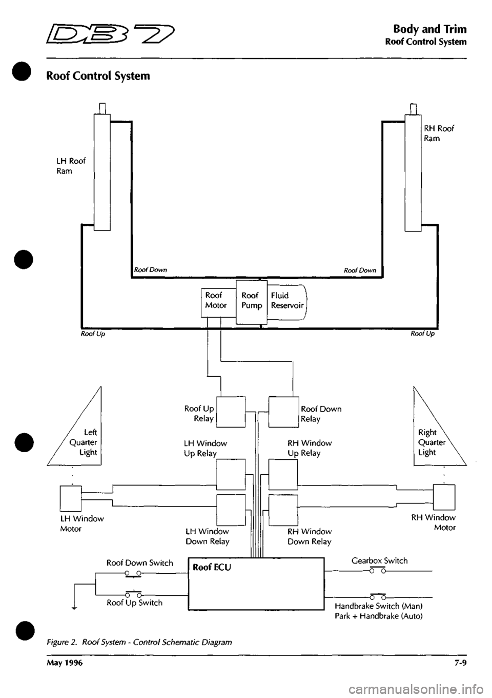
Roof Control System
LH Roof
Ram
n
Roof Down Roof Down
n
RH Roof
Ram
Roof
Motor
Roof Up
Fluid
Reservoir I
Roof Up
Roof Up
Relay
LH Window
Up Relay
LH Window
Motor LH Window
Down Relay
Roof Down Switch
-o o-
Roof Down
Relay
RH Window
Up Relay
Right
Quarter
Light
RH Window
Down Relay
RH Window
Motor
Gearbox Switch
o~o
o o-Handbrake Switch (Man)
Park + Handbrake (Auto)
Figure 2. Roof System - Control Schematic Diagram
May 1996 7-9
Page 304 of 421
^?
Air Conditioning
Upper Feedback Potentiometer / Servo Motors
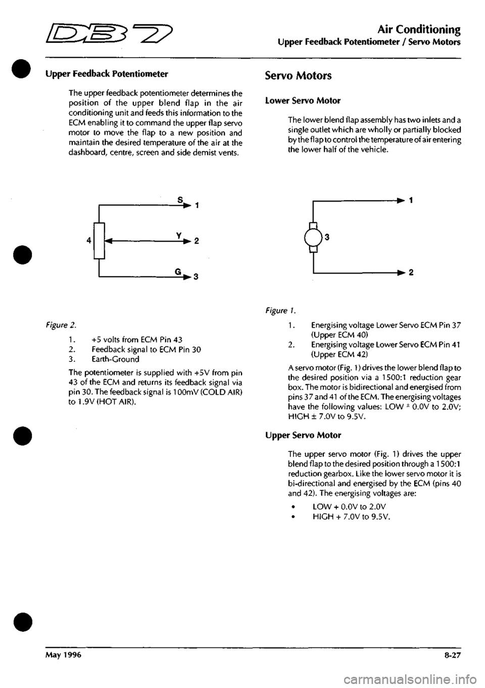
Upper Feedback Potentiometer
The upper feedback potentiometer determines the
position of the upper blend flap in the air
conditioning unit and feeds this information to the
ECM enabling it to command the upper flap servo
motor to move the flap to a new position and
maintain the desired temperature of the air at the
dashboard,
centre, screen and side demist vents.
Servo Motors
Lower Servo Motor
The lower blend flap assembly has two inlets and a
single outlet which are wholly or partially blocked
by the flap to control the temperature of air entering
the lower half of the vehicle.
V 1
-•2
V3 -•2
Figure
2.
1.
2.
3.
+5 volts from ECM Pin 43
Feedback signal to ECM Pin 30
Earth-Ground
The potentiometer is supplied with +5V from pin
43 of the ECM and returns its feedback signal via
pin 30. The feedback signal is
1
OOmV (COLD AIR)
to 1.9V (HOT AIR).
Figure L
1.
Energising voltage Lower Servo ECM Pin 37
(Upper ECM 40)
2.
Energising voltage Lower Servo ECM Pin 41
(Upper ECM 42)
A servo motor
(Fig.
1) drives the lower blend flap to
the desired position via a 1500:1 reduction gear
box. The motor is bidirectional and energised from
pins 37 and
41
of the
ECM.
The energising voltages
have the following values: LOW ± O.OV to 2.0V;
HIGH± 7.0V to 9.5V.
Upper Servo Motor
The upper servo motor (Fig. 1) drives the upper
blend flap to the desired position through a 1500:1
reduction gearbox. Like the lower servo motor it is
bi-directional and energised by the ECM (pins 40
and 42). The energising voltages are:
LOW + O.OV to 2.0V
HIGH + 7.0V to 9.5V.
May 1996 8-27
Page 391 of 421
The Aston Martin Lagonda Diagnostic System
Users Guide ^=2?
Transmission Diagnostics
Automatic transmission DB7s are fitted with a GM4L80-
E gearbox electronically controlled by a Transmission
Control Unit (TCM)
The TCM is mounted on the rear left wheel
arch.
It may be
electronically accessed from the upper diagnostic socket.
The TCM continuously monitors requests made by the
driver via the gear selector, throttle pedal, mode switch,
etc. This data is used in conjunction with speed input from
the transmission unit to calculate the optimum shift points
undercurrentconditions.Shiftpressureand ignition retard
are also controlled from this data to enhance shift quality
and reduce transmission wear.
TheTCM also detects faults within the transmission system
and stores the relevant fault codes for later analysis.
Gearshifts are controlled by two solenoid valves and a
pressure regulator within the transmission valve block
assembly.
If a serious fault occurs, the TCM removes all electrical
power from these valves and the transmission defaults to
a 'limp home' condition. In this state, only mechanical
selection of either reverse or second gear is available.
Gearshift Timing
Inputs from the performance mode switch (Sport, Normal
or 1st Gear Inhibit) and the throttle position sensor are
used to modify transmission gearshift operation
as
required
by the driver.
Sport mode raises the roadspeed at which gearshifts occur
enabling higher acceleration rates for the vehicle.
1st gear inhibit prevents engagement of first gear to reduce
the risk of wheel slip in icy conditions.
The throttle position sensor signal is continuously
monitored by the TCM to detect a rapid throttle opening.
If the throttle position sensor signal rises rapidly to above
4.5 volts, a 'Kickdown' condition is initiated. In this
condition,
upshifts are delayed to higher road speeds to
provide the higher acceleration required for overtaking
etc.
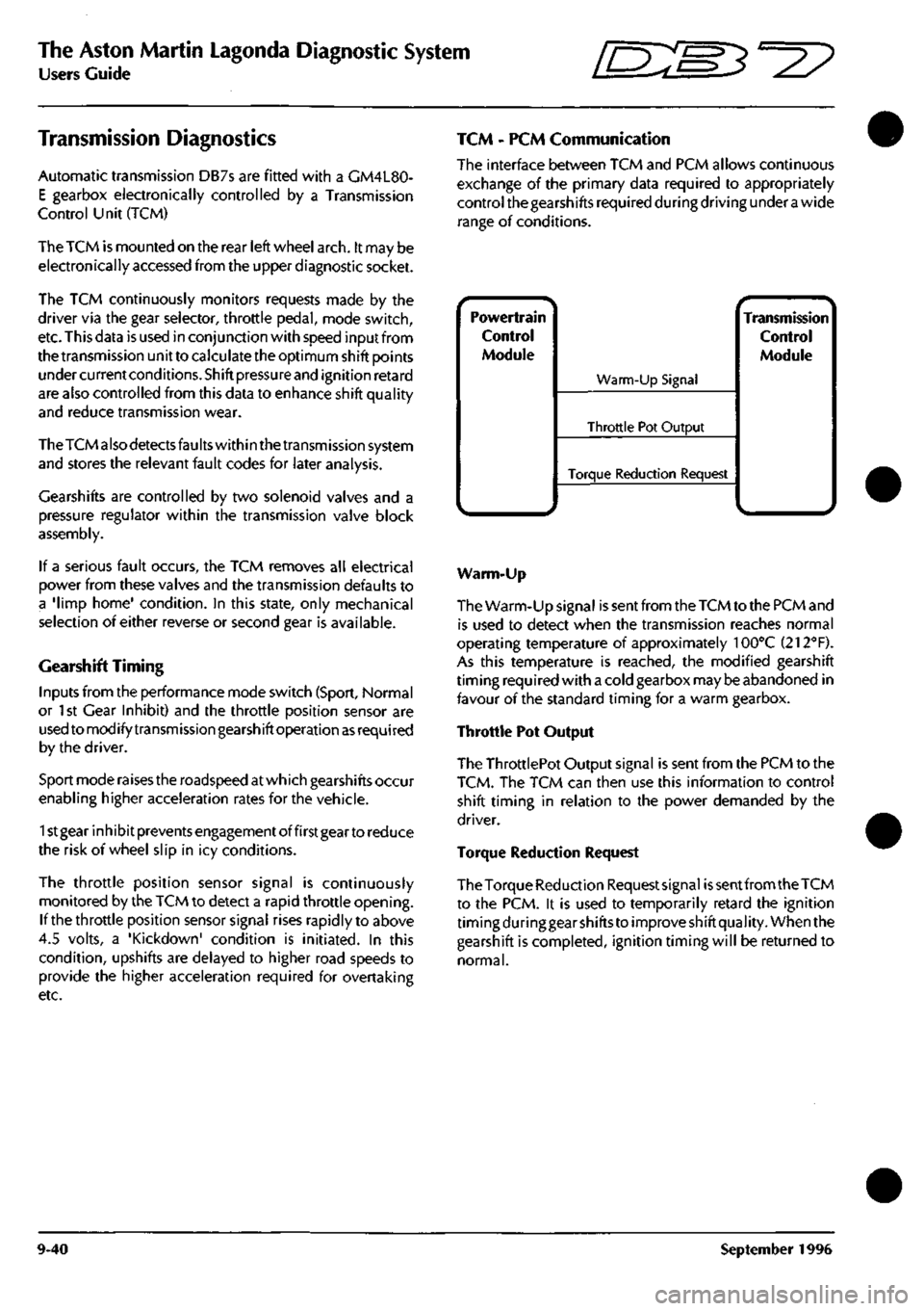
TCM - PCM Communication
The interface between TCM and PCM allows continuous
exchange of the primary data required to appropriately
control the gearshifts required during driving under
a
wide
range of conditions.
Powertrain
Control
Module
^.. ^
Warm-Up Signal
Throttle Pot Output
Torque Reduction Request
^ •- -^ Transmission
Control
Module
Warm-Up
The Warm-Up signal is sent from the TCM to the PCM and
is used to detect when the transmission reaches normal
operating temperature of approximately 100°C (212"'F).
As this temperature is reached, the modified gearshift
timing required with a cold gearbox may be abandoned in
favour of the standard timing for a warm gearbox.
Throttle Pot Output
The ThrottlePot Output signal is sent from the PCM to the
TCM.
The TCM can then use this information to control
shift timing in relation to the power demanded by the
driver.
Torque Reduction Request
The Torque Reduction Requestsignai
is
sent from the TCM
to the PCM. it is used to temporarily retard the ignition
timing during gear shifts to improve shift quality. When the
gearshift is completed, ignition timing will be returned to
normal.
9-40 September 1996