fuse ASTON MARTIN DB7 1997 Owner's Manual
[x] Cancel search | Manufacturer: ASTON MARTIN, Model Year: 1997, Model line: DB7, Model: ASTON MARTIN DB7 1997Pages: 421, PDF Size: 9.31 MB
Page 262 of 421

y/--^^^^3^
'—-p "^ Body and Trim
Roof Description
Volante Roof
Description
The system comprises an electrically driven hydraulic pump and two hydraulic rams for raising and lowering the
roof.
The pump is powered via two heavy duty changeover relays. Two further pairs of changeover relays power
the rear quarter windows (one pair for each window). The roof hydraulic pump is protected by a 30A fuse, the
windows by circuit breakers.
An electronic control module (ECM) is actuated by the roof switch on the centre console. The ECM controls the
operation of
both
the roof
and
rear quarter window circuits
so
that they can only be operated in
a
pre-programmed
manned.
When in operation, the ECM provides signals to the roof and to the rear quarter windows.
When the roof
switch
is moved into the open (Roof Down) position, the roof
and
rear windows move together until
approximately four seconds has elapsed. At this time, the ECM will remove power from the rear window circuits,
leaving the roof motor running. The roof motor will stop after 12 seconds (i.e. a further 8 seconds after the rear
window motors stop).
The signals will be removed from the rear window relay after 4 seconds and from the roof relay after 12 seconds
if the roof switch is held in either position for longer than 12 seconds.
In order to comply with legislation, the following features are built into the system:
If the roof switch is operated in either direction and then released before that operation is complete, the roof and
rear quarter windows will stop immediately. If, whilst the system is in operation, the ignition switch
is
turned to the
off position, the system will immediately stop.
If the roof switch is pressed again after pausing during a roof movement, the timing sequence will be as follows:
1.
If the previous direction is selected, the timing recommences from where it left off and will continue to
completion. If the ignition has been turned off, the timing will start from the beginning of its cycle.
2.
If theoppositedirection
is
selected,
the timing sequence will commence
from the beginning
of the newly selected
direction and continue to completion.
Roof and Rear Quarter Light Control
The following diagrams show the component location and the electrical control for the roof and rear quarter light
systems.
May 1996 7-7
Page 263 of 421

Body and Trim >/—^
^^^^5^
' ^ ^
Roof Components I -^' ^—^ -^-^
Roof Component Location
Roof Switch
Hydraulic Pump
ECM
Roof Up Relay
Roof Down Relay
LH Q Light Up Relay
LH Q Light Down Relay
RH Q Light Up Relay
RH Q Light Down Relay
Fuse and Circuit Breakers
Hydraulic Rams
Heated Rear Window Overide Switch
Figure 7. Roof
System
Component Location
7-8 May 1996
Page 360 of 421

^^?
The Aston Martin Lagonda Diagnostic System
I nstal lation I nstructions
Bench Mounting
The base station may also be mounted on a bench, which
must be in a safe position, stable and protected form
hazards and impacts. The base station must be mounted
at the back of the bench. 'Z' clips are provided for
permanent mounting. The bench surface must be kept free
from dust at all times.
CAUTION:
A gap under the base station must be
maintained free from obstructions to allow a flow of air
under the unit for cooling.
Electronic Module installation
WARNING: The base station electronic module must be
disconnected from the mains supply prior to installation/
removal from the base station assembly. DO NOT
reconnect to the mains supply until the module is safely
fitted into the base station. This unit must be earthed.
Note:
Users in North America are advised to replace the
ceramic mains fuse in the electronic module with theglass
fuse supplied.
Procedure
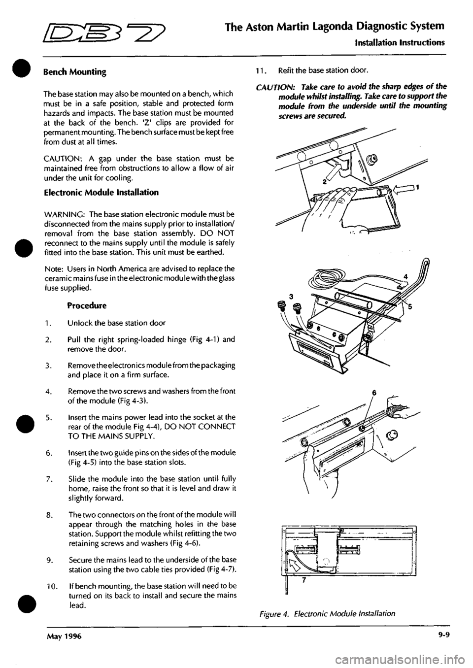
1.
Unlock the base station door
2.
Pull the right spring-loaded hinge (Fig 4-1) and
remove the door.
3. Removetheelectronicsmodulefrom the packaging
and place it on a firm surface.
4.
Remove the two screws and washers from the front
of the module (Fig 4-3).
5. Insert the mains power lead into the socket at the
rear of the module Fig 4-4), DO NOT CONNECT
TO THE MAINS SUPPLY.
6. Insert the two guide pins on the sides of the module
(Fig 4-5) into the base station slots.
7. Slide the module into the base station until fully
home,
raise the front so that it is level and draw it
slightly forward.
8. The two connectors on the front of the module will
appear through the matching holes in the base
station.
Support the module whilst refitting the two
retaining screws and washers (Fig 4-6).
9. Secure the mains lead to the underside of the base
station using the two cable ties provided (Fig 4-7).
10.
If bench mounting, the base station will need to be
turned on its back to install and secure the mains
lead.
11.
Refit the base station door.
CAUTION: Take care to avoid the sharp edges of the
module whilst installing. Take care to support the
module from the underside until the mounting
screws are secured.
Figure 4. Electronic Module Installation
May 1996 9-9
Page 367 of 421

The Aston Martin Lagonda Diagnostic System
Installation Instructions ^7
Problem Solving
CAUTION: If any part of the
system
is damaged, do not use it. Call your local GenRad Service Centre immediately for
a substitute
part.
Refer to 'Parts Ordering'.
CAUTION: With the exception of
those
parts referred to in the Servicing and Maintenance section, there are no user
serviceable parts. All servicing must be carried out by GenRad Service Centres.
PDU Self-Test
The system self test routine should be run periodically even if there are no apparent problems with the system.
Running the system self-test will identify any problems before they impact on productivity.
If it is suspected that the system is operating incorrectly, run the PDU system self test option on the main menu).
If the system self test will not run, or the PDU will not switch on, the instructions in this section must be followed
carefully.
If one of the fol lowing test steps advises you to order or fit a new part, make a note of the test step, part number and
description. Then follow the parts ordering procedure later in this section.
Stepi
Connect the mains power to the base station. Is the green base station indicator illuminated?
YES - Go to step 4
NO - Go to step 2
Step 2
Check the mains supply, then check the mains
lead.
Is
the mains lead faulty?
YES - Renew the mains
lead.
NO - Go to step 3
Step 3
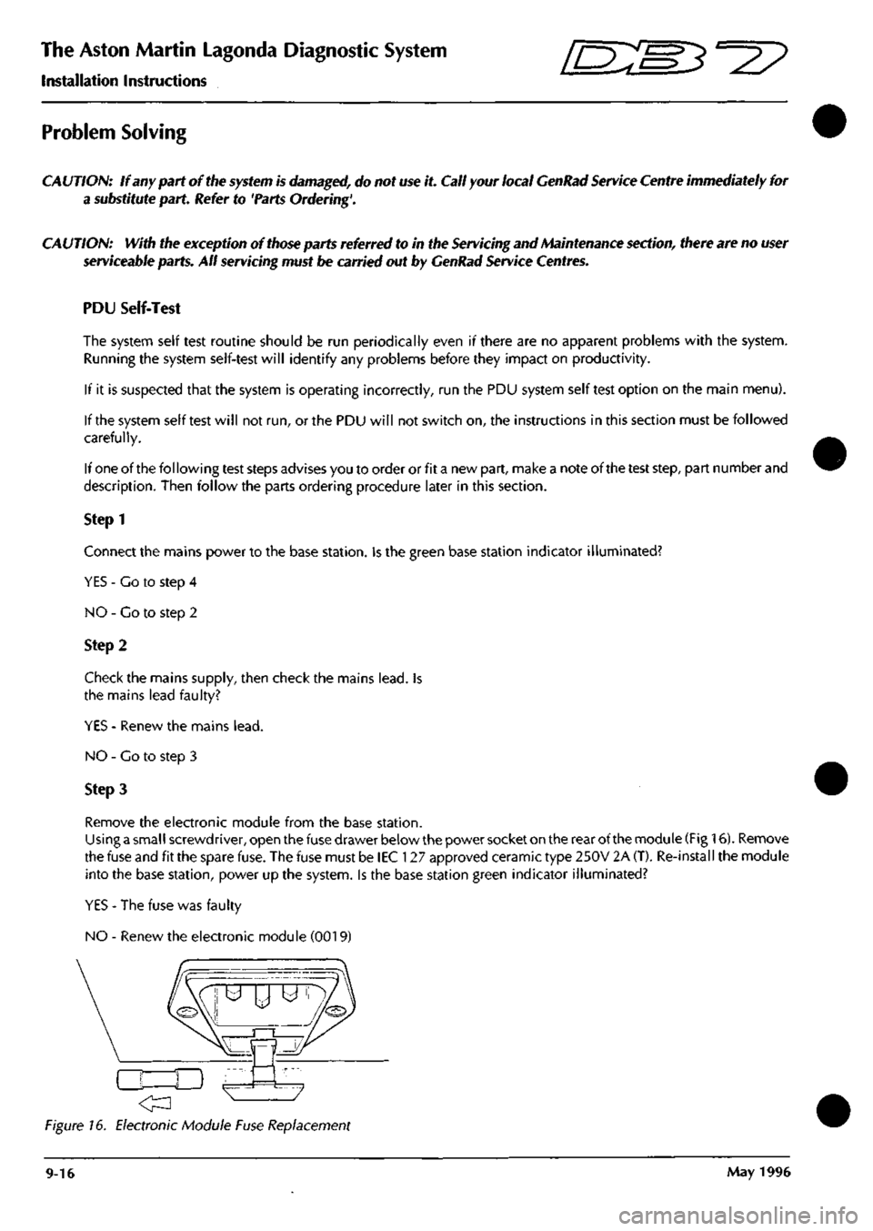
Remove the electronic module from the base station.
Using a small screwdriver, open the fuse drawer below the power socket on the rear of the module (Fig 16). Remove
the fuse and fit the spare fuse. The fuse must be lEC 127 approved ceramic type 250V 2A (T). Re-install the module
into the base station, power up the system. Is the base station green indicator illuminated?
YES - The fuse was faulty
NO - Renew the electronic module (0019)
Figure 16. Electronic Module Fuse Replacement
9-16 May 1996
Page 397 of 421

The Aston Martin Lagonda Diagnostic System //~~^ ^?~?^ " ^ ^
Users Guide
Airbag Diagnostic Trouble Code Monitor
The following diagnostic trouble codes are supported by the Airbag Control Module:
12 Low battery voltage
13 Air bag circuit shorted to ground
14 Front inpact sensor circuit shorted to ground
21 Safing impact sensor incorrectly mounter to vehicle
22 Safing impact sensor output shorted to battery voltage
23 Safing impact sensor input feed / return open circuit
24 Safing impact sensor output feed / return open circuit
32 Driver side airbag circuit high resistance or open
33 Passenger side airbag circuit high resistance or open
34 Driver side airbag circuit low resistance or short circuit
41 Front right impact sensor feed / return open circuit
42 Front left impact sensor feed / return open circuit
44 Front right impact sensor incorrectly mounted to vehicle
45 Front left impact sensor incorrectly mounted to vehicle
51 Airbag CM internal thermal fuse - intermittent short to ground
52 Back up power supply - voltage boost fault
53 Front impact sensor circuits resistance to ground or internal Airbag CM failure
9-46 September 1996