display ASTON MARTIN DB7 1997 Workshop Manual
[x] Cancel search | Manufacturer: ASTON MARTIN, Model Year: 1997, Model line: DB7, Model: ASTON MARTIN DB7 1997Pages: 421, PDF Size: 9.31 MB
Page 307 of 421
Air Conditioning
System Fault Diagnosis ^=2?
System Fault Diagnosis
Probable causes of faults can be found by comparing actual system pressures, registered on the manifold gauge set
or recovery-recharge-recycie station, and the pressure to temperature relationship graphs found on the previous
page.
The chart below shows the interpretation that may be made by this difference. The 'Normal' condition is that
which is relevant to the prevailing ambient and evaporator temperatures.
Note: If erratic or
unusual gauge movements
are experienced, check the equipment
against a
known manifold
gauge
set.
Low Side
Normal
Gauge
Normal to low
Low
Low
Low
Low
High
High
High Side Gauge
Normal
Normal
Low
Low
Low
Normal to high
Low
High
High
Fault Finding
High
Symptom
Discharge air initially cool
then warms up
As above
Discharge air slightly cool
Discharge air warm
Discharge air slightly cool or
frost build up at expansion
valve
Discharge air slightly cool
Compressor noisy
Discharge air warm and high
side pipes hot
Discharge air warm
Sweating or frost at evaporator
Diagnosis
Moisture in system
As above
HFC 134A charge low
HFC 134A charge very low
Expansion valve stuck closed
Restriction in High side of system
Defective reed valve
HFC 134A charge high or
condenser malfunction
Expansion valve stuck open
Caution:
The microprocessor is extremely sensitive
and should only
be tested
using
a
digital multimeter with no
less
than a 3.5
digit display and a
resistance
of no
less than
2 M
ohms.
The use
of any other form of multimeter will
damage the microprocessor
irreparably.
Note: Always allow time for the
servo
motors and blower motors to come to a
rest
before starting a
check.
The car should be in a workshop and the ambient
temperature
should
be
stable
e.g.
24''C
(75°F)
for at
least
30 minutes before
commencing the automatic
check.
At 24°C the
sensor
voltage is
2.972
V
± 2 mV.
The
rate of
change
is lOmVper
1
°C.
Unless
stated
otherwise,
all
checks
are carried out at the ECM
test plugs
Mode Switch: Off Ignition Switch: Aux 2
Signal Pin No.
Battery supply 1
Recirc input 9
Earth-ground 2
Earth-ground 6
Earth-ground 10
Earth-ground 38
Earth-ground 45
From mode switch 44
To mode switch 12
Voltage
n to 14v
0to2V
0 to 40mV
0 to 40mV
0 to 40mV
0 to 40mV
0 to 40mV
0 to 12V
10 to 13.3V
8-30 May 1996
Page 316 of 421
^=2?
Air Conditioning
System Checking with the Manifold Gauge Set
System Checking with the Manifold
Gauge Set
Connecting the Manifold Gauge Set
Caution: Only use hoses with connectors which are
dedicated to HFC 134A charge ports.
Attachmentofthehosequick release connectors to
the high and low side
system
ports
is
straightforward,
provided that the high and low valves are closed
and the system is NOT operational.
Assessment ofthe system's operating system can be
carried out by using the facilities ofthe Recovery-
Recharging-Recycling station. Follow the
manufacturer's instructions carefully and closely
observe the safety procedures.
Warning: Under no circumstances should the connections
be made with the
system
in operation or the
valves
open. Should the valves be open and a vacuum
pump or refrigerant container attached, an
explosion could occur
as
a result of high pressure
refrigerant being forced back into the vacuum
pump or container.
Stabilising the System
Accurate test gauge data can be attained only if the
system temperatures and pressures are stabilised.
Ensure that equipment and its hoses cannot come
into contact with moving parts or heat sources.
It is recommended that a free standing air mover is
placed in front of the vehicle to provide mass air
flow through the condenser-cooling system.
Checking Procedure
Connecting the Gauge Set.
A test hose connected to the fitting directly under
the low side gauge is used to connect the low side
ofthe test manifold into the low side ofthe system,
and a similar connection is found on the high side.
When connecting the gauge manifold set to the air
cond ition i ng system an access va Ive core removi ng
tool is available for connecting the test hoses to the
high and low sides ofthe system.
Using the valve removing tool it enables the valve
core to be removed and held back inside the tool
eliminating restrictions and, thereby, providing a
full flow of refrigerant.
Warning: Do not open the high side hand valve while the
air conditioning system is in operation because,
high pressure refrigerant will be forced through
the high side gauge and to the refrigerant container,
if it is attached.
This
could cause the container to
rupture or the fitting at the safety container valve
to burst resulting in damage and personal injury.
1.
With theengineswitched off, remove the protective
caps from the schraeder valves.
2.
Fit the access valve removal tool to the schraeder
valves. Ensure that both the manifold hand valves
are in the closed position.
3. Connect the high pressure manifold gauge hose (to
the high pressure side of the air conditioning side of
the system (high side is always the line from the
compressor to the condenser). Connect the low
pressure or compound gauge hose to the low
pressure side ofthe air conditioning system.
4.
Using the access valve removal tool loosen and
screw out the valve cores.
1.
Start the engine and allow it to attain normal
working temperature then set it at fast idle (typically
1200 to ISOOrpm).
2.
Select full air conditioning performance.
3. With all temperatures and pressures stable or
displaying symptoms of faults, begin relevant test
procedures.
May 1996 8-39
Page 325 of 421
Air Conditioning
Refrigerant Recovery and Recycling ^=2?
Recovery Procedure
Hote:
Run the
air-conditioning
system
for
a
few
minutes
before starting the
recovery
procedure as
this will
enable
more refrigerant to be recovered. Turn the
system
off
before
starting
the procedure.
1.
Attach the red (high side) hose oftheunittothe high
side fitting of the system on the vehicle then fit the
blue (low side) fitting to the low side on the vehicle.
Note: Make sure that the Air conditioning
system
has
pressure in it before beginning the recovery
process;
if
there is no
system
pressure there is no refrigerant to
recover.
Also
make sure that the
oil
drain
valve
is
closed.
2. Open both the high and low side valves on the
control panel.
3. Open the red CAS (vapour) valve and the blue
LIQUID valve on the tank.
4.
Turn on the MAIN POWER switch.
5. Press the RECOVERY key on the key-pad. The
display shows that the unit in the RECOVER mode
and AUTOMATIC cycle. After the compressor starts
the display shows the weight of refrigerant being
recovered.
The compressor shuts off automatically
when the recovery is complete and the display
shows the message 'CPL' and the final weight of the
recovered refrigerant.
6. Wait for five minutes and watch the manifold
gauges for a rise above 0. If a rise occurs press the
HOLD/CONT key. Repeat as needed until the
system pressure holds for two minutes.
Note: Drain the oil
separator
after
each
job.
7. Slowly open the oil drain valve and drain the oil
into the oil catch bottle. When all the recovered oil
has completely drained close the valve.
8. Replace oil lost during the recovery procedure by
measuringthe amount of oil inthe catch bottle and
adding the same amount of new oil to the system.
Note:
Dispose
of the
recovered
oil in an approved way.
9. When the recovery tank is full the compressor is
shut off and the display shows the message FULL.
Evacuating and Recycling the Refrigerant
1.
Open the red (high side) and the blue (low side)
valves on the unit and open the red GAS (vapour)
valve and the blue LIQUID valve on the tank.
2.
Enter the required time using the key-pad, press
enter,thedisplayshowstheenteredtime in minutes.
3. Start the vacuum pump by pressing the VACUUM
KEY again. The recycling process begins
approximately five seconds after the vacuum pump
starts and the message RECYCLE is displayed.
Note: If the vacuum pump
has
run for ten hours or
over
without an oil change the
message
OIL
flashes
on the
display.
Change
the pump oil and
then press
the
SHIFT/
RESET key and
the
zero key to
reset the
oil
change
timer
to zero.
The digital display counts down the evacuation
time.
4.
Check for non-condensibles after five minutes
recycling.
Ifthegauge needles are more than lOpsi
apart purge the non-condensibles from the tank by
open
i ng
the purge valve on the back of the
un
it and
continue to bleed until both needles show the same
reading.
The vacuum sequence continues until the
programmed time has elapsed at which point the
message CPL is displayed.
5. If the moisture indicator turns green recharge with
refrigerant.
or
5. If the moisture indicator has not turned green
replace the unit's filter-drier, which is probably
saturated.
Note:
Pressing
any key at this point allows the next
function to be
accessed.
To recycle the refrigerant only without pulling a
vacuum for an indefinite period of time press the
SHIFT/RESET key and the RECYCLE key on the key
pad.
Press the SHIFT/RESET key to cancel.
For vacuum only press the SHIFT/RESET key and
the ENTER key and then press
"1".
Run the vacuum
pump as long as required and then press
"1"
or
press SHIFT/RESET to cancel.
8-48 May 1996
Page 326 of 421
^2?
Air Conditioning
System Recharging / Compressor Oil Check
Recharging the System
1.
Open the high side valve on the unit control panel.
If the messages PROGRAM and CHARGE are not
displayed press the CHG key to enter PROGRAM
mode.
2.
Key in the amount of refrigerant needed to recharge
the system and press ENTER.
3. Press the CHG key; the message AUTOMATIC and
the entered amount of refrigerant wi
11
be displayed.
The display counts down to zero as the charging
process proceeds. When the charging is complete
the message CPL is displayed.
If the refrigerant transfer is too slow the charging
unit emits a signal. If the message CHECK
REFRIGERANT is not displayed, close the high side
valve,
open the low side valve and start the air
conditioning system to pull the remainder of the
charge into the system.
If the refrigerant transfer will not complete and the
message CHECK REFRIGERANT is displayed, press
the HOLD/CONT key to interrupt the cycle then
reset the unit by pressing the RESET key. Recover
the refrigerant already charged into the system by
following the procedure for recovering the
refrigerant, add new refrigerant to the tank and
return to Step 1 to recharge the system.
4.
If the air conditioning system is not running start it
and let it run until the gauge pressure readings
stabilize (compare the gauge readings with the
system manufacturer's specifications).
Note:
Ensure
that the
readings
are accurate by closing
both the high and low side
valves
on the unit's control
panel.
5. Check the evaporator outlet temperature to make
sure that the air conditioning system is operating
properly (refer to the system manufacturer's
specifications for the proper temperature).
Compressor Oil Checic
Data
Special Tools
Sanden oil dipstick JD 149
Torque Figures
Oil filler plug 8-12 Nm
Procedure
Whenever a component has been replaced in the
refrigerator system or there is an obvious oil leak, the
following procedure should be carried out.
A Sanden oil dipstick and angle gauge are required in
order to carry out the check.
1.
Run the compressor for 10 minutes at engine idle
speed.
2.
Depressurise the system.
3. Lay the angle gauge across the flat surfaces of the
two front mounting lobes. Centre the bubble and
note the mounting angle.
4.
Remove the compressor from the vehicle.
3. Remove the plug from the oil filler hole
(1
Fig. 1).
4.
Rotate the counter weight (3 Fig. 1) on the front of
theclutchtoallowthedipstick(2 Fig. 1)to penetrate
to its fullest extent.
Figure 1.
5. Insert the dipstick to its stop position (4 Fig. 1). The
point of dipstick angle should be facing left.
6. Removethedipstickandchecktheoil levelagainst
the figures quoted in the chart below.
May 1996 8-49
Page 343 of 421
Air Conditioning
Portable Diagnostic Unit - Signal Monitoring 3^^?
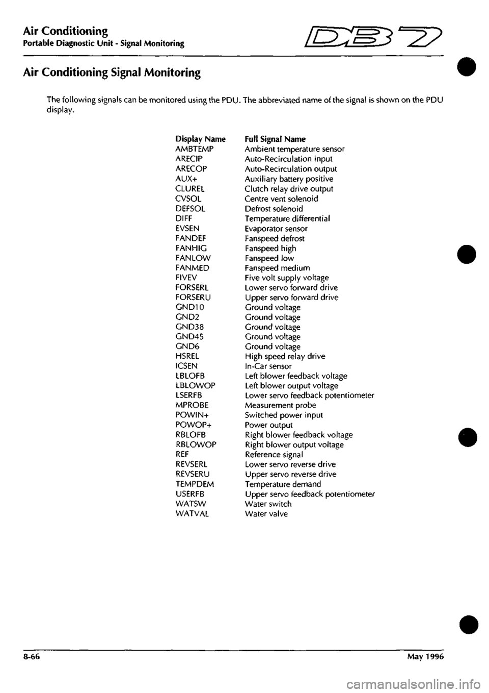
Air Conditioning Signal Monitoring
The following signals can be monitored using the PDU. The abbreviated name of the signal is shown on the PDU
display.
Display Name Full Signal Name
AMBTEMP Ambient temperature sensor
ARECIP Auto-Recirculation input
ARECOP Auto-Recirculation output
AUX+ Auxiliary battery positive
CLUREL Clutch relay drive output
CVSOL Centre vent solenoid
DEFSOL Defrost solenoid
DIFF Temperature differential
EVSEN Evaporator sensor
FANDEF Fanspeed defrost
FANHIG Fanspeed high
FAN LOW Fanspeed low
FANMED Fanspeed medium
FIVEV Five volt supply voltage
FORSERL Lower servo forward drive
FORSERU Upper servo forward drive
GND10 Ground voltage
GND2 Ground voltage
GND38 Ground voltage
GND45 Ground voltage
GND6 Ground voltage
HSREL High speed relay drive
ICSEN In-Car sensor
LBLOFB Left blower feedback voltage
LBLOWOP Left blower output voltage
LSERFB Lower servo feedback potentiometer
MPROBE Measurement probe
POWIN+ Switched power input
POWOP+ Power output
RBLOFB Right blower feedback voltage
RBLOWOP Right blower output voltage
REF Reference signal
REVSERL Lower servo reverse drive
REVSERU Upper servo reverse drive
TEMPDEM Temperature demand
USERFB Upper servo feedback potentiometer
WATSW Water switch
WATVAL Water valve
8-66 May 1996
Page 355 of 421
The Aston Martin Lagonda Diagnostic System
Installation Instructions "^P
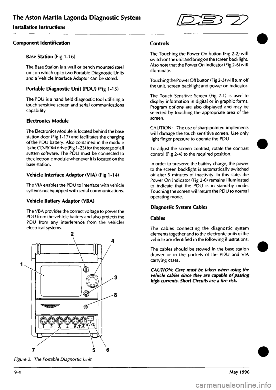
Component Identification
Base Station (Fig
1
-16)
The Base Station is a wall or bench mounted steel
unit on which up to two Portable Diagnostic Units
and a Vehicle Interface Adaptor can be stored.
Portable Diagnostic Unit (PDU) (Fig 1-15)
The PDU is a hand held diagnostic tool utilising a
touch sensitive screen and serial communications
capability
Electronics Module
The Electronics Module is located behind the base
station door (Fig
1
-17) and facilitates the charging
of the PDU battery. Also contained in the module
is
the CD-ROM drive (Fig
1
-23) for the storage of
al I
system software. The PDU must be connected to
the electronic modu le whenever it is located on the
base station.
Vehicle interface Adaptor (VIA) (Fig
1
-14)
The VIA enables the PDU to interface with vehicle
systems not equipped with serial communications.
Vehicle Battery Adaptor (VBA)
The VBA provides the correct voltage to power the
PDU from the vehicle battery and also protects the
PDU from any interference from the vehicles
electrical systems.
Controls
The Touching the Power On button (Fig 2-2) will
switch on the unit and bringon the screen backlight.
Also note that the Power On Indicator (Fig 2-6) will
illuminate.
Touching the Power Off button (Fig 2-3) will turn off
the unit, screen backlight and power on indicator.
The Touch Sensitive Screen (Fig 2-1) is used to
display information in digital or in graphic forms.
Program options are also displayed and may be
selected by touching the appropriate area of the
screen.
CAUTION:
The use of sharp pointed implements
will damage the touch sensitive screen. Use only
light finger pressure to operate the PDU.
To adjust the screen contrast, rotate the contrast
control (Fig 2-4) to the required position.
In order to preserve the battery charge, the power
to the screen backlight is automatically switched
off after 5 minutes of inactivity. In this state, the
Power On indicator (Fig 2-6) remains illuminated
to indicate that the PDU is in stand-by mode.
Touching the screen will return the PDU to normal
operating mode.
Diagnostic System Cables
Cables
The cables connecting the diagnostic system
elements together and to the electronic units of the
vehicle are identified in the following illustrations.
The cables should be stowed in the base station
drawer or in the pockets of the PDU and VIA
carrying cases.
CAUTION: Care must be taken when using the
vehicle cables since they are capable of
passing
high currents. Short Circuits are a fire
risk.
7 5 6
Figure 2. The Portable Diagnostic Unit
9-4 May 1996
Page 364 of 421
^^?
The Aston Martin Lagonda Diagnostic System
Installation Instructions
Powering-Up the PDU
1.
Install the CD-ROM.
2.
Press the PDU power on switch (Fig 1-2). An
audible tone will be hears and the green PDU
power on indicator (Fig 1-6) will illuminate. The
touch sensitive screen will also be activated. If this
does not happen, see the problem solving section.
3. Adjust the contrast control (Fig
1
-4).
4.
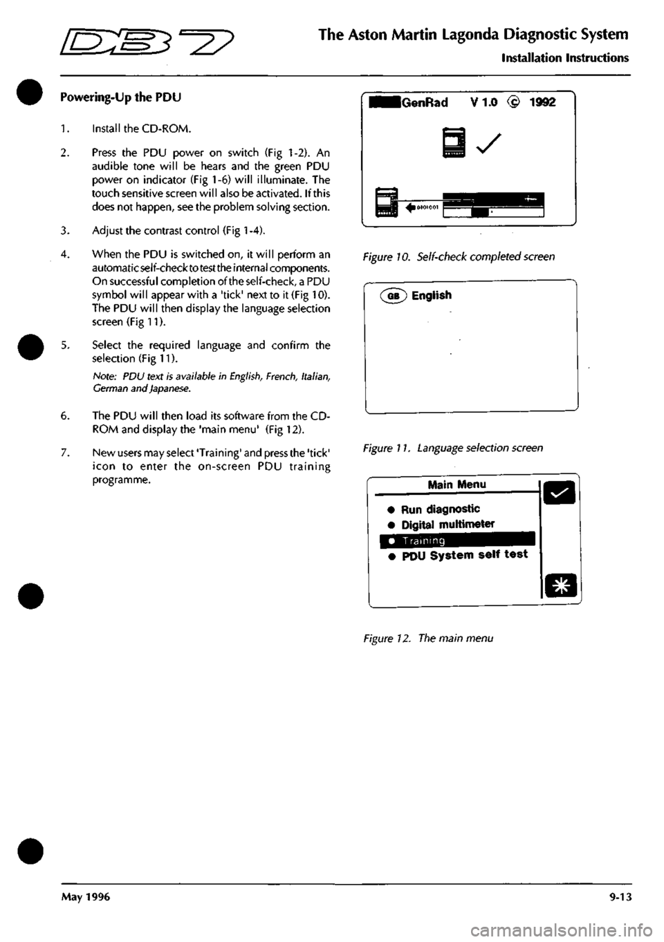
When the PDU is switched on, it will perform an
automaticself-checktotesttheinternal components.
On successful completion of the self-check, a PDU
symbol will appear with a 'tick' next to it (Fig 10).
The PDU will then display the language selection
screen (Fig 11).
5. Select the required language and confirm the
selection (Fig 11).
Hole: PDU text is available in
English,
French,
Italian,
German and Japanese.
6. The PDU will then load its software from the CD-
ROM and display the 'main menu' (Fig 12).
7. New users may select 'Training' and press the 'tick'
icon to enter the on-screen PDU training
programme.
iGenRad V 1.0 (£) 1992
y
Figure 10. Self-check completed screen
Figure 17. Language selection screen
Main Menu
• Run diagnostic
• Digital multimeter
Training
• PDU System self test
Figure 12. The main menu
May 1996 9-13
Page 365 of 421
The Aston Martin Lagonda Diagnostic System
Installation Instructions 5^27
Battery Charging
The PDU is fitted with internal NICAD batteries
which allow the PDU to be transported whilst
retaining programs. The batteries are not designed
to be used as a general power source. A special
circuit monitorstheamountofcharge in the batteries
so that they cannot be overcharged.
From the time when first operating the system or a
PDU fitted with substitute batteries, it will take up
to 36 hours to achieve full charge. In the meantime,
the PDU can be used whilst connected to the base
station or to the vehicle battery. Keep transit times
to and from the vehicle as short as reasonably
possible to preserve battery charge.
Subsequent battery charges
shou Id
take six to seven
hours from fully discharged. The PDU must always
be left connected to the base station when not in
use in order to keep the batteries fully charged.
CAUTION: The rechargeable NICAD batteries
fitted to the PDU are of a special type and must
only be replaced with GenRad approved parts. Do
not substitute the batteries with any other type.
Always
dispose
of old batteries in compliance with
local recycling regulations. The procedure for
changing the battery pack
is
described later in this
installation guide.
Operating Procedures
Refer to the Aston Martin Diagnostic System Users
Guide for detail on each of the PDU software
options
Selecting Diagnostics
1.
Switch on the PDU, the main menu will be
displayed.
2.
Select 'Run Diagnostic' from the main menu and
confirm the selection by pressing the 'tick'
icon.
A
sequence of menus will be displayed requesting
identification of the vehicle under test.
3. The system will load the appropriate software.
4.
On completion of software loading, disconnect the
PDU from the base station and transfer it in its
carrying case to the vehicle. The additional pockets
in the carrying case may be used for carrying any
interface cables required.
5. If the VIA is required, also transfer it in its carrying
case to the vehicle together with any vehicle
interface cable required.
Using the PDU on the Vehicle
At the vehicle, the PDU may be removed from its
carrying case if required. The PDU should always
be connected to the vehicle using the Vehicle
Battery Adaptor (VBA) (0024). The PDU will
continue to charge from the vehicle battery.
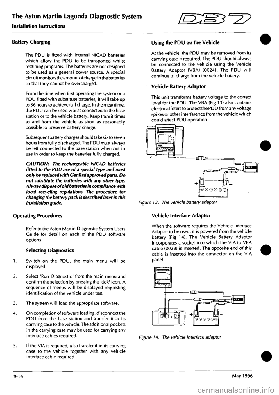
Vehicle Battery Adaptor
This unit transforms battery voltage to the correct
level for the PDU. The VBA (Fig 13) also contains
electrical filters to protect the PDU from any voltage
spikes or other interference from the vehicle which
could affect PDU operation.
f=l
a
OOOOOQS.fl
-dlD:
Figure 13. The vehicle battery adaptor
Vehicle Interface Adaptor
When the software requires the Vehicle Interface
Adaptor to be used, it is powered from the vehicle
battery (Fig 14). The Vehicle Battery Adaptor
incorporates a socket into which the VIA to VBA
cable (0028) is inserted. The opposite end of this
cable is inserted into the connector on the VIA
panel.
_a
hOOOOQpH"
-CIC=
=dD
n
S
© ® ® ® © ©
Figure 14. The vehicle interface adaptor
9-14 May 1996
Page 369 of 421
The Aston Martin Lagonda Diagnostic System
Installation Instructions -=2?
Step 11
Adjust the contrast control. Is the PDU touch screen illuminated?
YES - Co to step 12
NO - Renew the PDU (0017)
Step 12
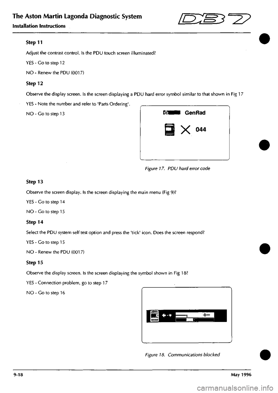
Observe the display screen. Is the screen displaying a PDU hard error symbol similar to that shown in Fig 17
YES - Note the number and refer to 'Parts Ordering'.
NO - Co to step 13
Figure 17. PDU hard error code
Step 13
Observe the screen display. Is the screen displaying the main menu (Fig 9)?
YES-Co to step 14
NO - Go to step 15
Step 14
Select the PDU system self test option and press the 'tick'
icon.
Does the screen respond?
YES - Co to step 15
NO - Renew the PDU (001 7)
Step 15
Observe the display screen. Is the screen displaying the symbol shown in Fig 18?
YES - Connection problem, go to step 17
NO - Co to step 16
Figure 18. Communications blocked
9-18 May 1996
Page 370 of 421
^^
The Aston Martin Lagonda Diagnostic System
Installation Instructions
Step 16
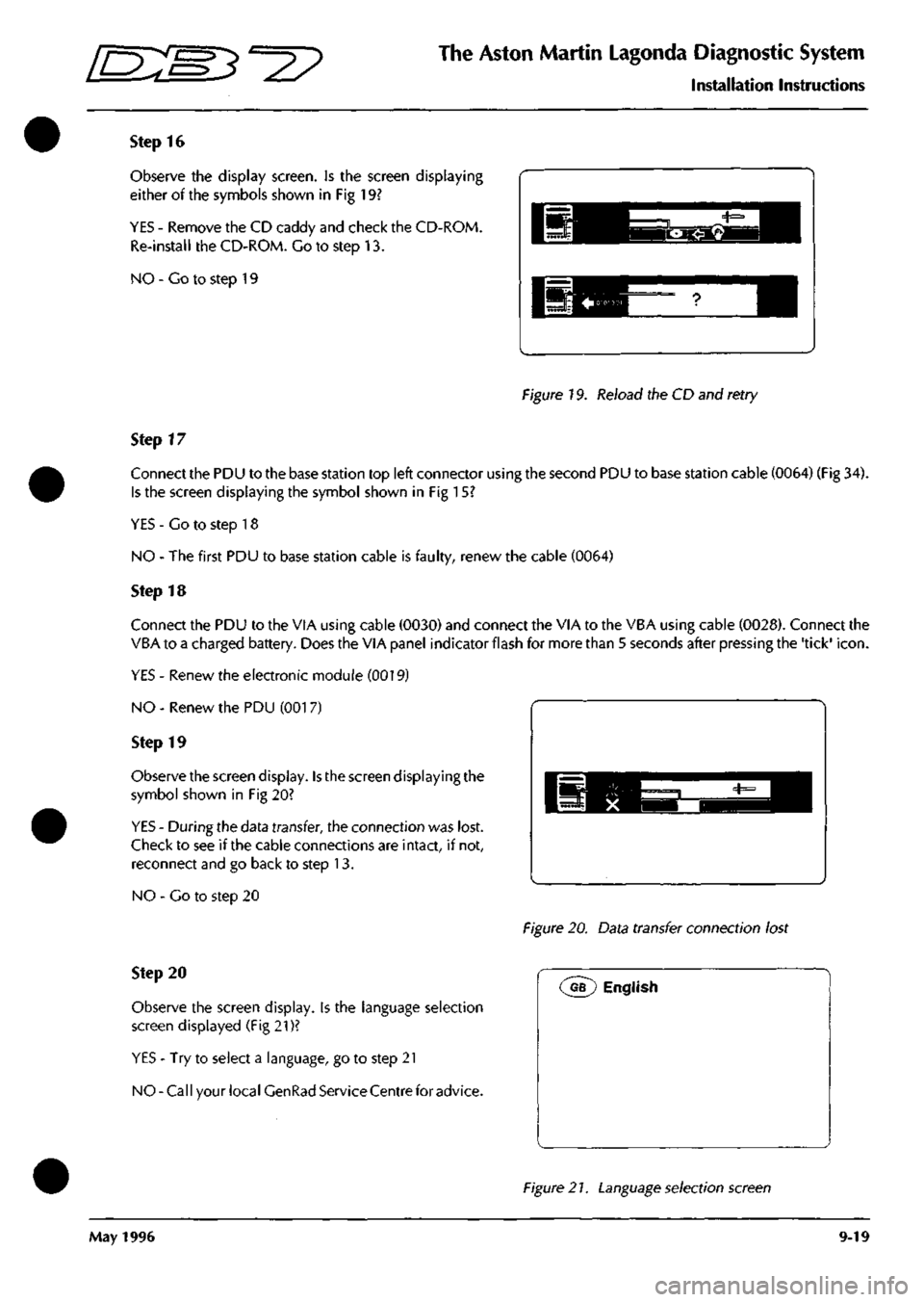
Observe the display screen. Is the screen displaying
either of the symbols shown in Fig 19?
YES - Remove the CD caddy and check the CD-ROM.
Re-install the CD-ROM. Go to step 13.
NO - Co to step 19
Figure 19. Reload the CD and retry
Step 17
Connect the PDU to the base station top left connector using the second PDU to base station cable (0064) (Fig 34).
Is the screen displaying the symbol shown in Fig 15?
YES - Go to step 18
NO - The first PDU to base station cable is faulty, renew the cable (0064)
Step 18
Connect the PDU to the VIA using cable (0030) and connect the VIA to the VBA using cable (0028). Connect the
VBA to a charged battery. Does the VIA panel indicator flash for more than 5 seconds after pressing the 'tick'
icon.
YES - Renew the electronic module (0019)
NO - Renew the PDU (001 7)
Step 19
Observe the screen display. Is the screen displaying the
symbol shown in Fig 20?
YES - During the data transfer, the connection was lost.
Check to see if the cable connections are intact, if not,
reconnect and go back to step 13.
NO - Go to step 20
Figure 20. Data transfer connection lost
Step 20
Observe the screen display, is the language selection
screen displayed (Fig 21)?
YES - Try to select a language, go to step 21
NO-Call your local GenRad Service Centre for advice.
(^G?) English
Figure 2
7.
Language selection screen
May 1996 9-19