display ASTON MARTIN DB7 1997 User Guide
[x] Cancel search | Manufacturer: ASTON MARTIN, Model Year: 1997, Model line: DB7, Model: ASTON MARTIN DB7 1997Pages: 421, PDF Size: 9.31 MB
Page 371 of 421

The Aston Martin Lagonda Diagnostic System
Installation Instructions =27
step 21
Observe the screen display. Is the system loading from the CD-ROM?
YES - Go to step 13.
NO - Renew the PDU (001 7).
Parts Ordering
Before calling GenRad, it is essential that the system self test is run from the main menu. If the system self test will
not run or the PDU does not switch on, follow the Problem Solving procedures.
The system self test option will identify any fau It and display a fault code on the PDU screen. This fault code number
must be recorded. When in contact with your local GenRad Service Centre, they will require this number in order
to send the correct substitute parts.
Before calling the GenRad Service Centre, please have the following information available.
Dealer Name and Address
Name of the contact at that address
PDU Serial Number (base station LHS - Fig 22)
Fault Code, Component Name and Serial Number as given on the PDU screen during self test.
Ifthe system self test will not run, GenRad will require the name and part number ofthe component identified during
he Problem Solving Procedures.
Figure 22. Diagnostic System Serial Number
9-20 May 1996
Page 381 of 421
The Aston Martin Lagonda Diagnostic System
Users Guide D-^?
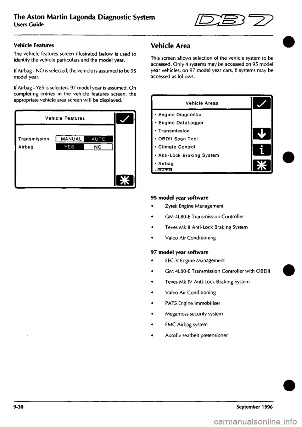
Vehicle Features
The vehicle features screen illustrated below is used to
identify the vehicle particulars and the model year.
If Airbag - NO is selected, the vehicle is assumed to be 95
model year.
If Airbag - YES is selected, 97 model year is assumed. On
completing entries in the vehicle features screen, the
appropriate vehicle area screen will be displayed.
Vehicle Features
Transmission MANUAL IIBIE^^I
Airbag IDS^I NO
D
Vehicle Area
This screen allows selection of the vehicle system to be
accessed.
Only 4 systems may be accessed on 95 model
year vehicles, on 97 model year cars, 8 systems may be
accessed as follows:
Vehicle Areas
• Engine Diagnostic
• Engine Datalogger
• Transmission
• OBDII Scan Tool
• Climate Control
• Anti-Lock Braking System
• Airbag
. lb Axol
o
PI
mLM
n
WLM
El
Ku^
95 model year software
Zytek Engine Management
GM 4L80-E Transmission Controller
Teves Mk II Anti-Lock Braking System
Valeo Air Conditioning
97 model year software
EEC-V Engine Management
CM 4L80-E Transmission Controller with OBDII
Teves Mk IV Anti-Lock Braking System
Valeo Air Conditioning
PATS Engine Immobiliser
Megamoss security system
FMC Airbag system
Autoliv seatbelt pretensioner
9-30 September 1996
Page 383 of 421
The Aston Martin Lagonda Diagnostic System
Users Guide "^7
Establishing Communications
when cable connections are completed, switch on the
vehicle ignition. The electronic control units will 'wake
up'
and communication between the selected control unit
and the PDU will be established.
As communication
is
established with the selected system,
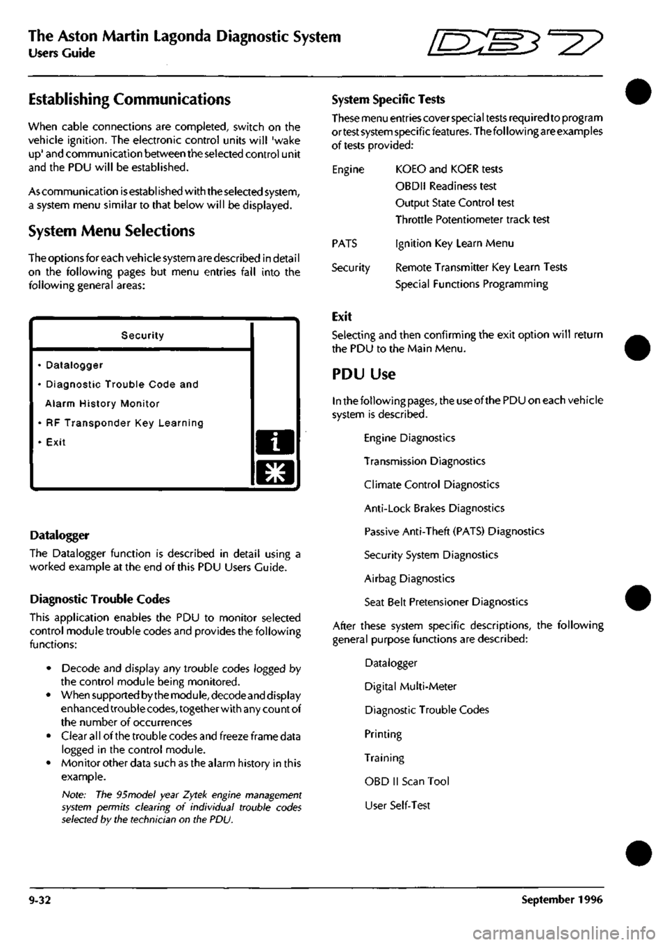
a system menu similar to that below will be displayed.
System Menu Selections
The options for each vehicle system are described in detai
I
on the following pages but menu entries fall into the
following general areas:
Security
• Datalogger
• Diagnostic Trouble Code and
Alarm History Monitor
• RF Transponder Key Learning
• Exit a
o
Datalogger
The Datalogger function is described in detail using a
worked example at the end of this PDU Users Guide.
Diagnostic Trouble Codes
This application enables the PDU to monitor selected
control module trouble codes and provides the following
functions:
• Decode and display any trouble codes logged by
the control module being monitored.
• When supported by the module, decodeand display
enhanced trouble
codes,
together with any count of
the number of occurrences
• Clear all of the trouble codes and freeze frame data
logged in the control module.
• Monitor other data such as the alarm history in this
example.
Note: The 95model year Zytek engine management
system permits clearing of individual trouble codes
selected by the technician on the PDU.
System Specific Tests
These menu entries cover special tests required to program
ortest system specificfeatures. The following are examples
of tests provided:
Engine KOEO and KOER tests
OBDII Readiness test
Output State Control test
Throttle Potentiometer track test
Ignition Key Learn Menu
Remote Transmitter Key Learn Tests
Special Functions Programming
PATS
Security
Exit
Selecting and then confirming the exit option will return
the PDU to the Main Menu.
PDU Use
In the following
pages,
the use of the PDU on each vehicle
system is described.
Engine Diagnostics
Transmission Diagnostics
Climate Control Diagnostics
Anti-Lock Brakes Diagnostics
Passive Anti-Theft (PATS) Diagnostics
Security System Diagnostics
Airbag Diagnostics
Seat Belt Pretensioner Diagnostics
After these system specific descriptions, the following
general purpose functions are described:
Datalogger
Digital Multi-Meter
Diagnostic Trouble Codes
Printing
Training
OBD II Scan Tool
User Self-Test
9-32 September 1996
Page 384 of 421
^27
The Aston Martin Lagonda Diagnostic System
Users Guide
Engine Diagnostics - 97 MY
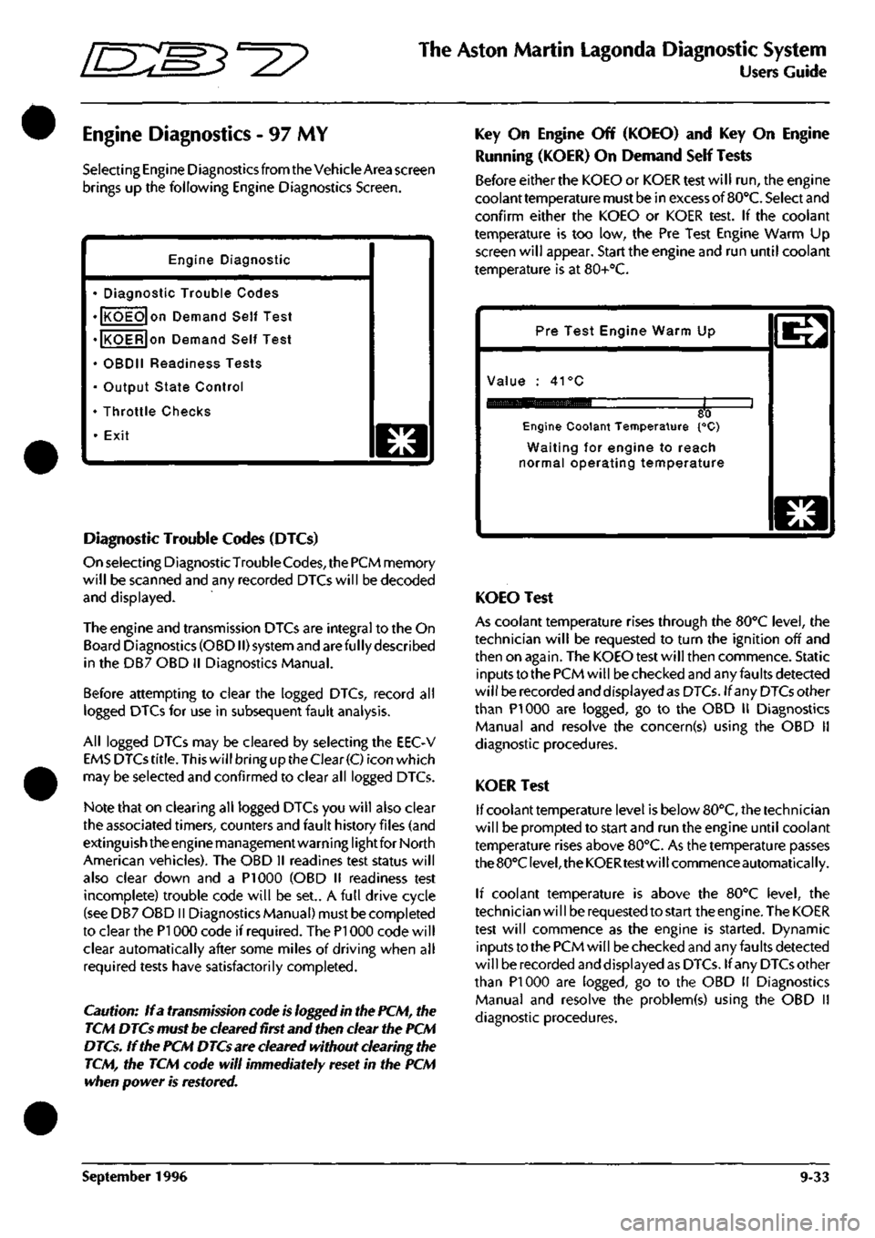
Selecting Engine Diagnostics from the Vehicle Area screen
brings up the following Engine Diagnostics Screen.
Engine Diagnostic
• Diagnostic Trouble Codes
• KOEO on Demand Self Test
• KOER on Demand Self Test
• OBDII Readiness Tests
• Output State Control
• Throttle Checks
• Exit
o
Diagnostic Trouble Codes (DTCs)
On selecting DiagnosticTrouble
Codes,
the PCM memory
will be scanned and any recorded DTCs will be decoded
and displayed.
The engine and transmission DTCs are integral to the On
Board Diagnostics (OBDII) system and are ful ly described
in the DB7 OBD II Diagnostics Manual.
Before attempting to clear the logged DTCs, record all
logged DTCs for use in subsequent fault analysis.
All logged DTCs may be cleared by selecting the EEC-V
EMS DTCs
title.
This will bring up the Clear
(C)
icon which
may be selected and confirmed to clear all logged DTCs.
Note that on clearing all logged DTCs you will also clear
the associated timers, counters and fault history files (and
extinguish the engine management warning lightfor North
American vehicles). The OBD II readines test status will
also clear down and a PI 000 (OBD II readiness test
incomplete) trouble code will be set.. A full drive cycle
(see DB7 OBD II Diagnostics Manual) must be completed
to clear the PI 000 code if required. The PI 000 code will
clear automatically after some miles of driving when all
required tests have satisfactorily completed.
Caution: If a transmission code is logged in the PCM, the
TCM DTCs must be cleared first and then clear the PCM
DTCs. If the PCM DTCs are cleared without clearing the
TCM, the TCM code will immediately reset in the PCM
when power is restored.
Key On Engine Off (KOEO) and Key On Engine
Running (KOER) On Demand Self Tests
Before either the KOEO or KOER test will run, the engine
coolant temperature must be in excess of
BO'C.
Select and
confirm either the KOEO or KOER test. If the coolant
temperature is too low, the Pre Test Engine Warm Up
screen will appear. Start the engine and run until coolant
temperature is at 80+°C.
Pre Test Engine Warm Up
Value : 41°C
80 Engine Coolant Temperature {°C)
Waiting for engine to reach
normal operating temperature
o
KOEO Test
As coolant temperature rises through the BO'C level, the
technician will be requested to turn the ignition off and
then on again. The KOEO test will then commence. Static
inputs to the PCM will be checked and any faults detected
will be recorded and displayed as DTCs. If any DTCs other
than PI 000 are logged, go to the OBD II Diagnostics
Manual and resolve the concern(s) using the OBD 11
diagnostic procedures.
KOER Test
If coolant temperature level is below 80°C, the technician
will be prompted to start and run the engine until coolant
temperature rises above 80°C. As the temperature passes
the 80°C
level,
the KOERtest will commence automatically.
If coolant temperature is above the 80°C level, the
technician wi
11
be requested to start the engine. The KOER
test will commence as the engine is started. Dynamic
inputs to the PCM will be checked and any faults detected
will be recorded and displayed as DTCs. If any DTCs other
than PI 000 are logged, go to the OBD 11 Diagnostics
Manual and resolve the problem(s) using the OBD II
diagnostic procedures.
September 1996 9-33
Page 389 of 421
The Aston Martin Lagonda Diagnostic System
Users Guide ^?
Engine Setup
- 95 MY
Two adjustments
may
beset with the aid of the PDU
on 95
MY vehicles.
• Throttle Potentiometer
• Idle Fuelling Trim
From
the 95 MY
Main Menu, make
and
confirm
the
following sequence
of
selections:
Diagnostics
/
Manual
or
Auto Transmission
/
Engine
/
Engine Setup
/
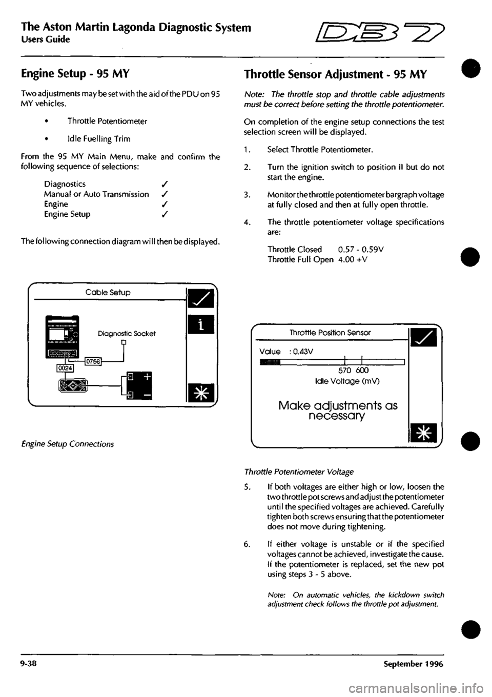
The following connection diagram will then be displayed.
Throttle Sensor Adjustment
- 95 MY
Note:
The
throttle stop
and
throttle cable adjustments
must
be
correct before setting
the
throttle potentiometer.
On completion
of the
engine setup connections
the
test
selection screen will
be
displayed.
1.
Select Throttle Potentiometer.
2.
Turn
the
ignition switch
to
position
II but do not
start
the
engine.
3. Monitorthethrottle potentiometer bargraph voltage
at fully closed
and
then
at
fully open throttle.
4.
The
throttle potentiometer voltage specifications
are:
Throttle Closed
0.57 -
0.59V
Throttle Full Open
4.00 +V
Cable Setup
Diagnostic Socket D
Engine Setup Connections
Tinrottle Position Sensor
Value
:
0.43V
570
600
Idle Voltage
(mV)
Make adjustments as
necessary
Throttle Potentiometer Voltage
5.
If
both voltages
are
either high
or low,
loosen
the
two throttle pot screws and adjust the potentiometer
until
the
specified voltages
are
achieved. Carefully
tighten both screws ensuringthat the potentiometer
does
not
move during tightening.
6.
If
either voltage
is
unstable
or if the
specified
voltages cannot
be
achieved, investigate the cause.
If
the
potentiometer
is
replaced,
set the new pot
using steps
3-5
above.
Note:
On
automatic vehicles,
the
kickdown switch
adjustment check follows the throttle
pot
adjustment.
9-38 September
1996
Page 390 of 421
ffi:
The Aston Martin Lagonda Diagnostic System
Users Guide
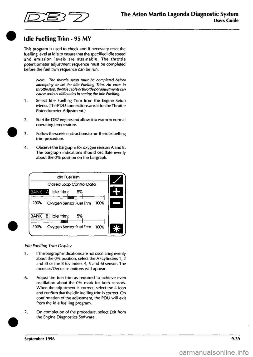
Idle Fuelling Trim - 95 MY
This program is used to check and if necessary reset the
fuelling level at idle to ensure that the specified idle speed
and emission levels are attainable. The throttle
potentiometer adjustment sequence must be completed
before the fuel trim sequence can be run.
Note: The throttle setup must be completed before
attempting to set the Idle Fuelling Trim. An error in
throttle
stop,
throttle cable or throttle pot
adjustments can
cause serious
difficulties in setting the Idle Fuelling.
Select Idle Fuelling Trim from the Engine Setup
Menu.
(The PDU connections are
as
fortheThrottle
Potentiometer Adjustment.)
1.
3.
StarttheDB7engineand allow itto warm to normal
operating temperature.
Followthescreeninstructionstorunthe idle fuelling
trim procedure.
Observe the bargraphs for oxygen sensors A and B.
The bargraph indications should oscillate evenly
about the 0% position on the bargraph.
BANK
-100%
BANK
-100%
Idle
Fuel
Trim
Closed Loop Control Data
Q Idle
trim:
8%
9^B 1 1
Oxygen Sensor Fuel Trim 100%
B Idle
trim:
5% —1 1 1
«^
1 1 Oxygen Sensor Fuel
Trim
100%
Idle Fuelling Trim Display
5. Ifthebargraphindicationsarenotoscillatingevenly
about the 0% position, select the A (cylinders 1, 2
and 3) or the B (cylinders 4, 5 and 5) sensor. The
Increase/Decrease buttons will appear.
6. Adjust the fuel trim as required to achieve even
oscillation about the 0% mark for both sensors.
When the adjustment is correct, select the 4 icon
and confirm that the idle fuelling trim is correct. On
confirmation of the adjustment, the PDU will exit
from the idle fuelling program.
7. On completion of the procedure, select Exit from
the Engine Diagnostics Software.
September 1996 9-39
Page 396 of 421

^^2?
The Aston Martin Lagonda Diagnostic System
Users Guide
Airbag System Diagnostics
WARNING: Whilst it
is
completely safe to
access
and read the airbag diagnostic module memory at
the diagnostic socket, significant personal risks
exist in the performance of any other
tasks
on the
airbag system or components. Therefore all
workshop manual warnings must be read and all
safety procedures must be followed before, during
and on completion of any other practical work on
the airbag system.
System Description
The airbag system installation comprises:
Airbag Diagnostic Module
Driver and passenger airbag modules
Two front impact (crash) sensors
One 'safing' sensor
Dedicated wiring harness
SRS indicator/warning lamp
The system is designed to provide protection for both
driver and front seat passenger by automatically
deploying airbags in the event of a collision during
forward travel.
Intheeventof
a
collision, the crash and safing sensors
will operate, completing the firing circuit and causing
the airbags to inflate within 32 milliseconds. At least
one crash sensor and the safing sensor must operate to
fire the airbags.
Any faults in system components, installation or wiring
will be indicated by a flashing code on the SRS/
AIRBAG warning lamp. Fault code information may
also be monitored using the PDU or scan
tool.
A full description of the airbag system components is
included in the workshop manual.
Airbag Diagnostics
The Airbag Control Module indicates a fault by
transmitting a pulsed signal down the Airbag System
Failure line to flash the SRS/AIRBAC warning lamp.
The fault code is repeated continuously. If there are
two or more faults, the fault code with the highest
priority is transmitted first. The second fault code is
only transmitted when the first fault has been rectified.
TheSRS/AIRBAC warning lamp is also used to indicate
any problem in the seat belt pretensioner system (if
fitted). Flashing of the lamp indicates an airbag fault,
constant illumination of the lamp indicates a seat belt
pretensioner fault.
At the top left of the PDU screen there is a bullet mark
which indicates the current state of the Airbag System
Failure line. As a code is transmitted the bullet mark
can be seen to flash.The PDU reads the fault code, and
writes the code number and fault description to the
screen.
The PDU continues to monitor the transmitted
code.
If the transmitted code changes, the new code
number and description will appear below the first.
PMC Airbag
32 Drivers airbag circuit
shorted or open
o
when remedial action has been taken to correct a
fault, press the Clear Button to clear down the PDU
display. Then use the PDU to ensure that no faults are
reported.
A series of audible beeps, continuously transmitted by
the Airbag Diagnostic Module, indicates that there is
an Airbag System fault to report and that the Airbag
System Failure line
is
open circuit. The PDU is notable
to monitor the fault line in this situation as there is no
pull-up resistor, normally provided by a warning lamp
in the instrument pack.
Rapid continuous flashing of the Instrument Pack
Airbag Failure Lamp indicates that both front impact
sensors are disconnected. No fault code is reported on
the PDU, however on close inspection the bullet mark
can be seen to flicker.
September 1996 9-45
Page 401 of 421
The Aston Martin Lagonda Diagnostic System
Users Guide ^=2?
Printer Use Digital Multimeter
Print Trace
The Trace Buffer is used to record technician use of the
PDU.As the diagnostics are executed, the following
information is written to trace:
Screen Title
Menu options selected
Operator questions selected
Operator actions
Control module information
Test limits and results
P codes detected by the DTC monitor
Snapshot data from the datalogger
OBD II freeze frame data
Set up the printer and load with paper. Select Print
Trace and confirm the selection. All recorded
information in the above list will be printed.
Printtrace is supported in English, French, German and
Italian.
Print Screen
The Print Screen function dumps a bitmap image of the
current screen display to the printer. This function is
particularly useful for recordingdata such as waveforms
captured by the datalogger application.
The print screen function is supported in English,
French,
German, Italian and Japanese.
Introduction
The Digital Multi-Meterprovidesthecapability to measure
voltage, current, resistance, frequency, pulse width, pulse
period and duty cycle using measurement probes or
vehicle interface adaptor channels.
WARNING: DMM measurements must not be taken
while the PDU
is
connected to the
base
station. The PDU
measurement system
becomes
referenced to earth when
connected to the base station. Serious measurement
errors may be present
because
of any voltage difference
between vehicle ground and base station earth. Operation
of the PDU in this mode has both functional and safety
implications and therefore must be
avoided.
A digital multimeter (DMM) is resident within the PDU
software toolbox.
The DMM application can be accessed from the main
menu.
On selection of "Digital Multimeter" from the main
menu,
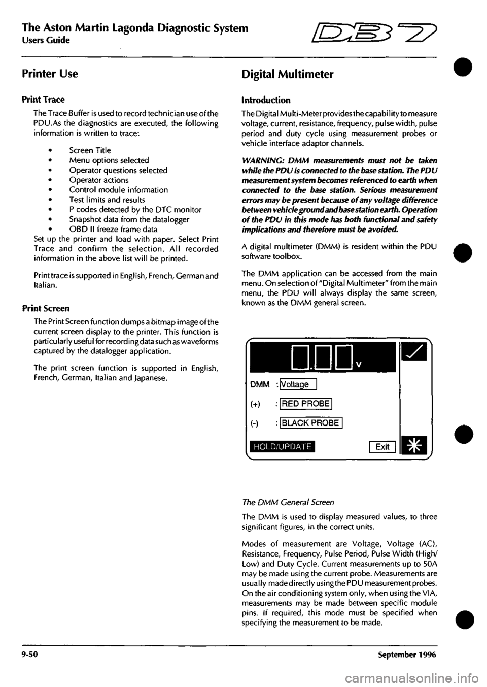
the PDU will always display the same screen,
known as the DMM general screen.
DDD
DMM : Voltage
(+) : RED PROBE
(-) : BLACK PROBE
HOLD/UPDATE Exit
The DMM General Screen
The DMM is used to display measured values, to three
significant figures, in the correct units.
Modes of measurement are Voltage, Voltage (AC),
Resistance, Frequency, Pulse Period, Pulse Width (High/
Low) and Duty Cycle. Current measurements up to 50A
may be made using the current probe. Measurements are
usually madedirectlyusingthe PDU measurement probes.
On the air conditioning system only, when using the VIA,
measurements may be made between specific module
pins.
If required, this mode must be specified when
specifying the measurement to be made.
9-50 September 1996
Page 402 of 421
^^?
The Aston Martin Lagonda Diagnostic System
Users Guide
Operation
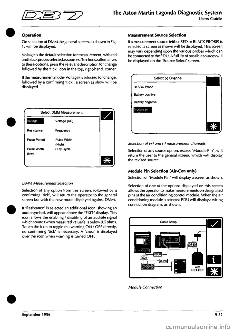
On selection of DMM the general screen, as shown in Fig.
1,
will be displayed.
Voltage is the default selection for measurement, with red
and black probes selected
as
sources.
To choose alternatives
to these options, press the relevant description for change
followed by the 'tick' icon in the top, right-hand, corner.
If the measurement mode (Voltage) is selected for change,
followed by a confirming 'tick', a screen as show will be
displayed.
Select DMM Measurement
^Q^||[
Resistance
Pulse Period
Pulse Width
(low)
Voltage (AC)
Frequency
Pulse Width
(High)
Duty Cycle
DMM Measurement Selection
Selection of any option from this screen, followed by a
confirming 'tick', will return the operator to the general
screen but with the new mode displayed against DMM.
If 'Resistance' is selected an additional
icon,
showing an
audio symbol, will appear above the "EXIT" display. This
icon allows the enabling / disabling of an audible signal
which sounds when measured valuefal
Is
below 0.5 ohms.
Touch the icon to toggle the warning ON / OFF directly,
no confirming 'tick' is necessary. A 'cross' is displayed
over the icon when warning is turned OFF.
Measurement Source Selection
If
a
measurement source (either RED or BLACK PROBE) is
selected,
a screen as shown will be displayed. This screen
may vary depending upon the various probes which can
be connected to the PDU.Afull list of possiblesources will
be displayed on the 'Source Select' screen.
Select (-) Channel
BLACK Probe
Battery positive
Battery negative
Module pin
Selection of (+) and (-) measurement channels
Selection of any source option, except "Module Pin", will
return the user to the general screen, which will display
the revised source.
Module Pin Selection (Air-Con only)
Selection of "Module Pin" will display a screen as shown.
Selection of one of the options displayed on this screen
allows the operator to make measurements on designated
pins of the air conditioning control module. When the air
conditioning module is selected PDU will display a wiring
connection diagram, as shown.
Cable Setup
Module Connection
September 1996 9-51
Page 403 of 421
The Aston Martin Lagonda Diagnostic System
Users Guide [S:S3^2?
The PDU will then check the cable connections. Until all
connections are correct, the PDU will not allow progression
beyond this
screen.
Pressingthe'asterisk'icon and selecting
abort returns the operator to the general screen if an
incorrect system has been chosen.
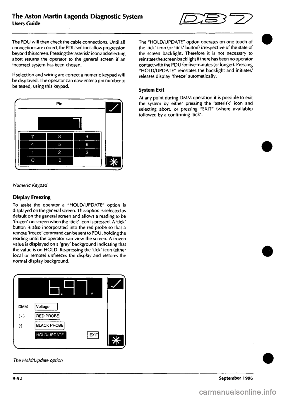
If selection and wiring are correct a numeric keypad will
be displayed. The operator can nowenterapin numberto
be tested, using this keypad.
Pin
Numeric Keypad
Display Freezing
To assist the operator a "HOLD/UPDATE" option is
displayed on the general screen. This option is selected as
default on the general screen and allows a reading to be
'frozen'
on screen when the 'tick' icon is pressed. A 'tick'
button is also incorporated into the red probe so that a
remote 'freeze' command can be sent to PDU, holding the
reading until the operator can view the screen. A frozen
value is displayed on a 'grey' background indicating that
the value is on HOLD. Re-pressing the 'tick' icon (either
local or remote) unfreezes the display and restores the
normal display background.
b.nn
DMM
(-)
(-)
Voltage
RED PROBE
BLACK PROBE
HOLD/UPDATE
The "HOLD/UPDATE" option operates on one touch of
the 'tick' icon (or 'tick' button) irrespective of the state of
the screen backlight. Therefore it is not necessary to
reinstate the screen backlight if there has been no operator
contact with the PDU for five minutes (or longer). Pressing
"HOLD/UPDATE" reinstates the backlight and initiates/
releases display 'freeze' automatically.
System Exit
At any point during DMM operation it is possible to exit
the system by either pressing the 'asterisk' icon and
selecting abort, or pressing "EXIT" (where available)
followed by a confirming 'tick'.
The Hold/Update option
9-52 September 1996