fuel ASTON MARTIN V8 VANTAGE 2010 Workshop Manual
[x] Cancel search | Manufacturer: ASTON MARTIN, Model Year: 2010, Model line: V8 VANTAGE, Model: ASTON MARTIN V8 VANTAGE 2010Pages: 947, PDF Size: 43.21 MB
Page 919 of 947

Aston Martin V12 Family
2009 MY V12 Family EOBDincl. V12 Vantage
Aston Martin/Ford Confidential
Component/ System Fault Code Monitor Strategy
Description Malfunction Criteria Threshold Parameter Secondary Parameters Entry Parameters Time Required DTC
StorageMIL Illumin-
ationStream 2 (CMS) O2
Sensor signal Stuck
Lean P2270
(Bank 1)
Monitor normal signal voltage
envelope; forced A/F
excursion if required for green
catalyst
(Rationality check) HO2S maximum signal
voltage
< 0.42 volts Inferred exhaust temp 149 - 760 deg C
(300 - 1400 deg F)Once per driving
cycleFootnote a) Footnote c)
P2272
(Bank 2) Stream 2 heater on time > 90 sec
Fuel level above minimum
level> 0.15 * 100 %
Throttle position Part throttle
Engine rpm - for forced
excursion only > 1000 rpm
Inferred exhaust temp - fo
r
forced excursion only < 871 deg C
(< 1600 deg F)
Flex fuel composition not
changing
Upstream sensor(s) tested
Stream 2 (CMS) O2
Sensor signal Stuck
Rich P2271
(Bank 1)
HO2S minimum signal
voltage> 0.48 volts Inferred exhaust temp 149 - 760 deg C
(300 - 1400 deg F)Once per driving
cycleFootnote a) Footnote c)
P2273
(Bank 2) Stream 2 heater on time > 90 sec
Fuel level above minimum
level> 0.15 * 100 %
Throttle position Part throttle
Engine rpm - for forced
excursion only > 1000 rpm
Inferred exhaust temp - fo
r
forced excursion only < 871 deg C
(< 1600 deg F)
Flex fuel composition not
changing
Upstream sensor(s) tested
Stream 2 (CMS)
HO2S Overvoltage Monitor HO2S voltage Voltage greater than
malfunction threshold> 1.1 volts
Stream 2 HO2S heater on
time > 90 sec
Continuous Footnote a) Footnote c)
Time with sensor voltage
out of range > 25 sec
Stream 2 HO2S:
Inferred sensor temp > 204 deg C
(> 400 deg F)
HO2S heater OK
(P0141, P0054-bank1)
(P0161, P0060-bank2)
P0138
(Bank 1)
P0158
(Bank 2) Monitor normal signal voltage
envelope; forced A/F
excursion if required for green
catalyst
(Rationality check)
8
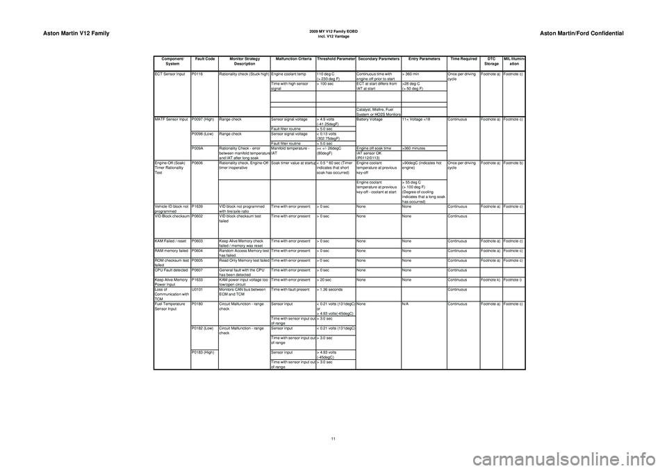
Page 922 of 947

Aston Martin V12 Family
2009 MY V12 Family EOBDincl. V12 Vantage
Aston Martin/Ford Confidential
Component/ System Fault Code Monitor Strategy
Description Malfunction Criteria Threshold Parameter Secondary Parameters Entry Parameters Time Required DTC
StorageMIL Illumin-
ation
Engine coolant temp 110 deg C (> 230 deg F)Continuous time with
engine off prior to start > 360 min
Time with high sensor
signal > 100 sec
ECT at start differs from
IAT at start >28 deg C
(> 50 deg F)
Catalyst, Misfire, Fuel
System or HO2S Monitors
Sensor signal voltage > 4.9 volts (-41.25degF)
Fault filter routine > 5.0 sec
Sensor signal voltage < 0.13 volts (302.75degF)
Fault filter routine > 5.0 sec Engine off soak time >360 minutes
IAT sensor OK
(P0112/0113)
Rationality check, Engine-Off
timer inoperative Soak timer value at startup < 0.5 * 60 sec (Timer
indicates that short
soak has occurred)Engine coolant
temperature at previous
key-off >90degC (indicates hot
engine)
Engine coolant
temperature at previous
key-off - coolant at start > 55 deg C
(> 100 deg F)
(Degree of cooling
indicates that a long soak
has occurred)
Vehicle ID block not
programmed P1639 VID block not programmed
with tire/axle ratio Time with error present > 0 sec
NoneNoneContinuous Footnote a) Footnote c)
VID Block checksum P0602 VID block checksum test failedTime with error present > 0 sec
NoneNoneContinuous
KAM Failed / reset P0603 Keep Alive Memory check failed / memory was resetTime with error present > 0 sec
NoneNoneContinuous Footnote a) Footnote c)
RAM memory failed P0604 Random Access Memory test has failed.Time with error present > 0 sec
NoneNoneContinuous Footnote a) Footnote c)
ROM checksum test
failed P0605 Read Only Memory test failed Time with error present > 0 sec
NoneNoneContinuous Footnote a) Footnote c)
CPU Fault detected P0607 General fault with the CPU has been detectedTime with error present > 0 sec
NoneNoneContinuous
Keep Alive Memory
Power Input P1633 KAM power input voltage too
low/open circuit Time with error present > 20 sec
NoneNoneContinuous Footnote k) Footnote i)
Loss of
Communication with
TCM U0101 Monitors CAN bus between
ECM and TCM Time with fault present > 1.36 seconds
Continuous
Sensor input < 0.21 volts (131degC)
or
> 4.93 volts(-45degC)
Time with sensor input out
of range > 3.0 sec
Sensor input < 0.21 volts (131degC)
Time with sensor input out
of range > 3.0 sec
Sensor input > 4.93 volts
(-45degC)
Time with sensor input out
of range > 3.0 sec 11< Voltage <18 Continuous Footnote a) Footnote c)
MATF Sensor Input P0097 (High) Range check Battery Voltage
P0098 (Low) Range check
P009A Rationality Check - error between manifold temperature
and IAT after long soak Manifold temperature -
IAT
>< +/- 26degC
(80degF)
ECT Sensor Input P0116 Rationality check (Stuck high)
Once per driving
cycleFootnote a) Footnote c)
Engine-Off (Soak)
Timer Rationality
Test P0606
Once per driving
cycleFootnote a) Footnote b)
Fuel Temperature
Sensor Input P0180
P0182 (Low)
P0183 (High)Circuit Malfunction - range
check
Circuit Malfunction - range
check
None
N/A Continuous Footnote a) Footnote c)
11
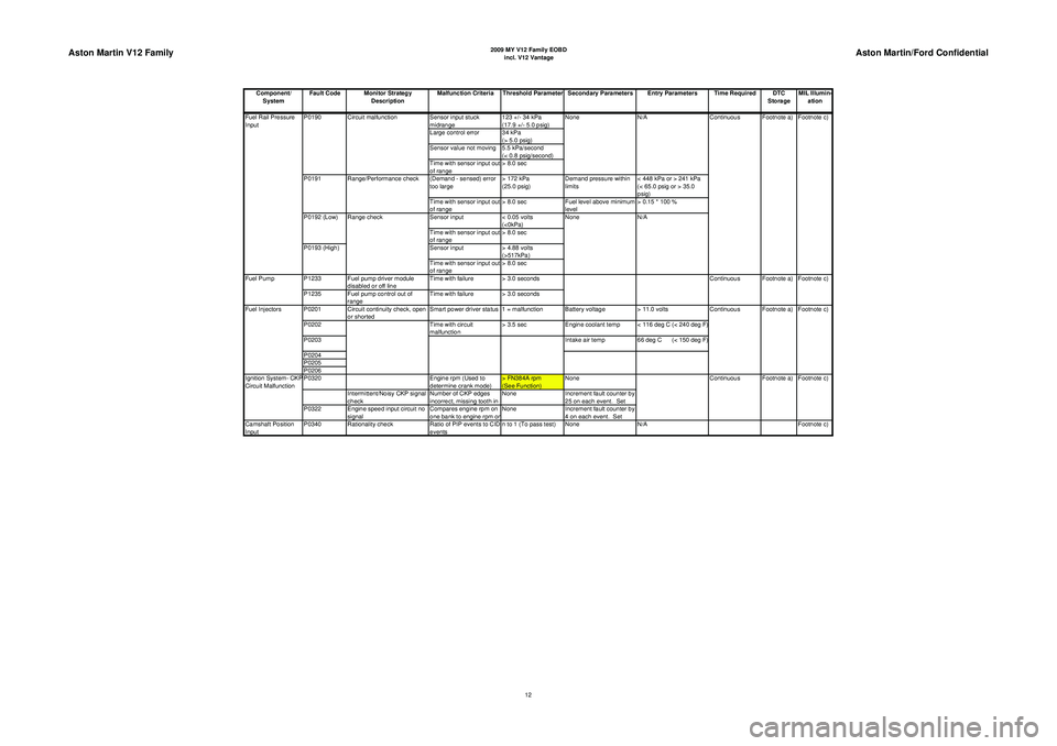
Page 923 of 947

Aston Martin V12 Family
2009 MY V12 Family EOBDincl. V12 Vantage
Aston Martin/Ford Confidential
Component/ System Fault Code Monitor Strategy
Description Malfunction Criteria Threshold Parameter Secondary Parameters Entry Parameters Time Required DTC
StorageMIL Illumin-
ation
Sensor input stuck
midrange 123 +/- 34 kPa
(17.9 +/- 5.0 psig)
Large control error 34 kPa (> 5.0 psig)
Sensor value not moving 5.5 kPa/second (< 0.8 psig/second)
Time with sensor input out
of range > 8.0 sec
(Demand - sensed) error
too large > 172 kPa
(25.0 psig)Demand pressure within
limits < 448 kPa or > 241 kPa
(< 65.0 psig or > 35.0
psig)
Time with sensor input out
of range > 8.0 sec
Fuel level above minimum
level > 0.15 * 100 %
Sensor input < 0.05 volts
(<0kPa)
Time with sensor input out
of range > 8.0 sec
Sensor input > 4.88 volts
(>517kPa)
Time with sensor input out
of range > 8.0 sec
P1233 Fuel pump driver module disabled or off line Time with failure > 3.0 seconds
P1235 Fuel pump control out of range Time with failure > 3.0 seconds
P0201 Circuit continuity check, open or shorted Smart power driver status 1 = malfunction Battery voltage
> 11.0 volts
P0202 Time with circuit
malfunction > 3.5 sec
Engine coolant temp < 116 deg C (< 240 deg F)
P0203 Intake air temp66 deg C (< 150 deg F)
P0204
P0205
P0206
P0320 Engine rpm (Used to
determine crank mode) > FN384A rpm
(See Function)None
Intermittent/Noisy CKP signal
check Number of CKP edges
incorrect, missing tooth in None
Increment fault counter by
25 on each event. Set
P0322 Engine speed input circuit no signal Compares engine rpm on
one bank to engine rpm o
nNone
Increment fault counter by
4 on each event. Set
Camshaft Position
Input P0340 Rationality check
Ratio of PIP events to CID
events n to 1 (To pass test) None
N/A Footnote c)
Footnote c)
Fuel Rail Pressure
Input P0190
P0191
P0192 (Low)
P0193 (High)Range check
Range/Performance check
Fuel Pump Continuous
Circuit malfunction N/A
Continuous Footnote a) Footnote c)
None
None
N/A Footnote a)
Fuel Injectors Footnote c)
Ignition System- CKP
Circuit Malfunction Continuous Footnote a) Footnote c)
Continuous Footnote a)
12
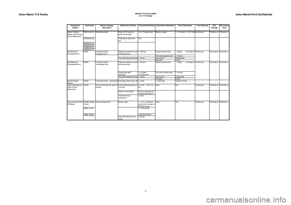
Page 924 of 947

Aston Martin V12 Family
2009 MY V12 Family EOBDincl. V12 Vantage
Aston Martin/Ford Confidential
Component/ System Fault Code Monitor Strategy
Description Malfunction Criteria Threshold Parameter Secondary Parameters Entry Parameters Time Required DTC
StorageMIL Illumin-
ation
P0351(Coil A) Ratio of PIP events to
spark events seen 1 to 1 (To pass test) Battery voltage
> 11.0 volts or < 18.0 volts Continuous Footnote a) Footnote c)
P0352(Coil B) PCM able to determine
coil Yes
P0353(Coil C)
P0354(Coil D)
P0355(Coil E)
P0356(Coil F) Functional check -
overspeed error Difference between actual
and desired rpm> -200 rpm
Engine coolant temp -7 deg C (> 20 deg F)
Time since engine start > 100 sec
Time with solenoid at limit > 15 sec Fuel controlClosed loop
Idle state At idle
Difference between actual
and desired rpm > 100 rpm
Engine coolant temp -7 deg C (> 20 deg F)
Closed loop MAF
correction > 4.5 g/sec
(> 0.6 lbs/min)Time since engine start > 100 sec
Time with solenoid at limit > 10 sec Fuel controlClosed loop
Idle state At idle
Vehicle Speed
Sensor P0500 Functional check - operational Evaluates CAN source VS > 3 mph
> 4 secondsVehicle moving
Commanded dutycycle on
or full-off >=0.135 * 100 % or =
0%None
N/A Continuous Footnote a) Footnote e)
Signal circuit voltage Refer to Appendix for threshold calculation
Time with circuit
malfunction > 5 sec
P0460 (Range
Check) Sensor input
<= 7 or >= 254 A/D
counts w/in a range of
256 A/D counts
P0462 (Low) < 7 A/D counts
P0463 (High) > 254 A/D counts
Time with sensor out of
range > 30 sec N/A
Continuous Footnote a) Footnote j)
Fuel Level Input Out
Of Range Sensor range check
None
Vapor Management
Valve Circuit
Malfunction
P0443 Circuit continuity test, open or
shorted Footnote a) Footnote c)
IAC Solenoid
Underspeed Error P0506 Functional check -
underspeed error Continuous
IAC Solenoid
Overspeed Error
P0507
Continuous Footnote a) Footnote c)
Ignition System-
Ignition Coil Primary
Circuit Malfunction
Rationality check
13
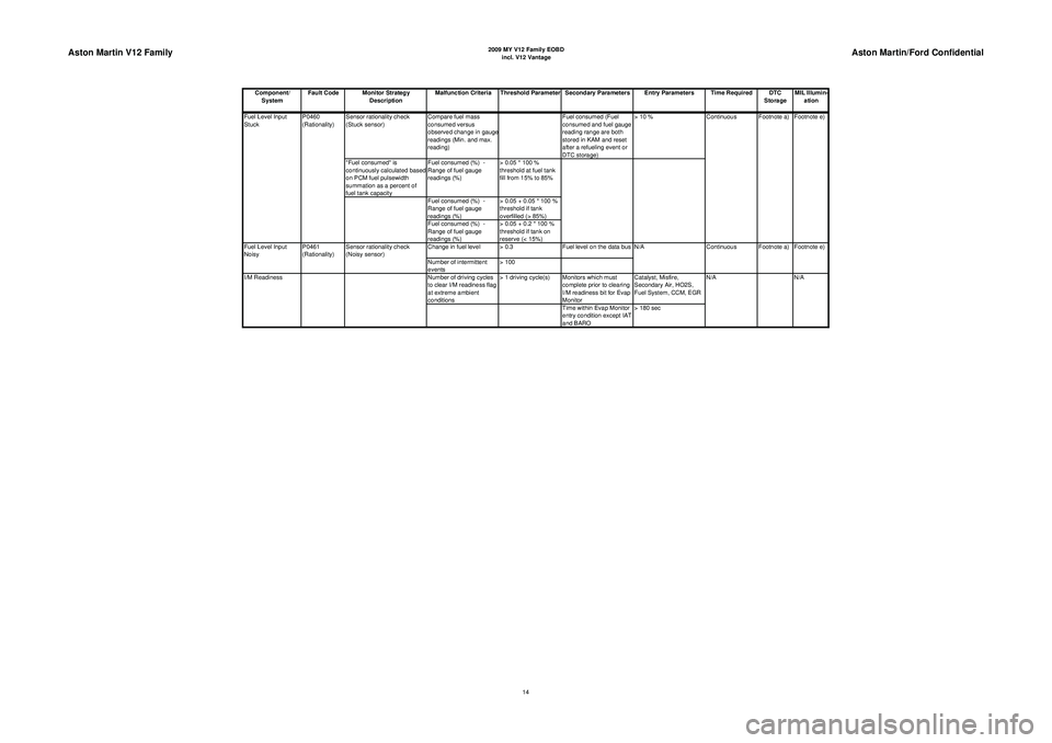
Page 925 of 947

Aston Martin V12 Family
2009 MY V12 Family EOBDincl. V12 Vantage
Aston Martin/Ford Confidential
Component/ System Fault Code Monitor Strategy
Description Malfunction Criteria Threshold Parameter Secondary Parameters Entry Parameters Time Required DTC
StorageMIL Illumin-
ation
Sensor rationality check
(Stuck sensor) Compare fuel mass
consumed versus
observed change in gaug
e
readings (Min. and max.
reading) Fuel consumed (Fuel
consumed and fuel gauge
reading range are both
stored in KAM and reset
after a refueling event or
DTC storage)> 10 %
"Fuel consumed" is
continuously calculated based
on PCM fuel pulsewidth
summation as a percent of
fuel tank capacity Fuel consumed (%) -
Range of fuel gauge
readings (%)
> 0.05 * 100 %
threshold at fuel tank
fill from 15% to 85%
Fuel consumed (%) -
Range of fuel gauge
readings (%) > 0.05 + 0.05 * 100 %
threshold if tank
overfilled (> 85%)
Fuel consumed (%) -
Range of fuel gauge
readings (%) > 0.05 + 0.2 * 100 %
threshold if tank on
reserve (< 15%)
Change in fuel level > 0.3 Fuel level on the data bus
Number of intermittent
events > 100
Number of driving cycles
to clear I/M readiness flag
at extreme ambient
conditions > 1 driving cycle(s) Monitors which must
complete prior to clearing
I/M readiness bit for Evap
Monitor Catalyst, Misfire,
Secondary Air, HO2S,
Fuel System, CCM, EGR
Time within Evap Monitor
entry condition except IAT
and BARO > 180 sec N/A
I/M Readiness N/AFootnote e)
Fuel Level Input
Noisy P0461
(Rationality)Sensor rationality check
(Noisy sensor) N/A
Continuous Footnote a) Footnote e)
Continuous Footnote a)
Fuel Level Input
Stuck P0460
(Rationality)
14
Page 929 of 947
![ASTON MARTIN V8 VANTAGE 2010 Workshop Manual Aston Martin V12 Family
2009 MY V12 Family EOBDincl. V12 Vantage
Aston Martin/Ford Confidential
FN654S (sec)
NONE [de
gC] -29 -7 21 38 60 123
output_axis [s] 1400 900 475 325 300 300
FN_TCSTRT (sec)
T ASTON MARTIN V8 VANTAGE 2010 Workshop Manual Aston Martin V12 Family
2009 MY V12 Family EOBDincl. V12 Vantage
Aston Martin/Ford Confidential
FN654S (sec)
NONE [de
gC] -29 -7 21 38 60 123
output_axis [s] 1400 900 475 325 300 300
FN_TCSTRT (sec)
T](/img/52/56974/w960_56974-928.png)
Aston Martin V12 Family
2009 MY V12 Family EOBDincl. V12 Vantage
Aston Martin/Ford Confidential
FN654S (sec)
NONE [de
gC] -29 -7 21 38 60 123
output_axis [s] 1400 900 475 325 300 300
FN_TCSTRT (sec)
TCSTRT [de
gc] -40 -18 -7 4 15 38 60 104 123
output_axis [s] 100 70 24 20 18 15 15 15 20
FN384A (RPM)
ECT [DEG. C] -160 -160 -29 -18 10 123
output_axis [RPM] 450 450 450 350 350 350
FN_FL_DT_MX (%)
PGM_FUEL_LVL [%] 0111111
output_axis [%]
0.2 0.2 0.2 0.2 0.2 0.2 0.2
IAT_RAT_THRES (deg F) BLANK_STRING 0123456789
output_axis [de
gF] 30 30 30 30 30 -30 -30 -30 -30 -30
18
Page 930 of 947

Aston Martin V12 Family
2009 MY V12 Family EOBDincl. V12 Vantage
Aston Martin/Ford Confidential
Notes:
1) "Continuous" under the "Time Required" column indicates that the specified test cycles at a frequency greater than once every 0.5
seconds whenever the test entr
y conditions are met.
2) "Once per driving cycle" under the "Time Required" column indicates that the specified test will complete during the first 2 bags of an
FTP as well as under the test entry conditions s
pecified
, on the road.
3
)All test entr
y condition
parameters are measured instantaneousl
y unless otherwise indicated.
Footnotes:Secondar
y Parameters:
p) If a 6 hour soak is met, some strategies will not require another continuous 6 hour soak if the customer performs a brief key-off. This
has been put into effect to im
prove eva
p monitor com
pletion fre
quenc
y.
q) Some strategies will have the ability to base evap monitor soak length on the CARB cold soak criteria which consists of an ECT range
and ACT/ECT differential.
r) A minimum soak time has been added to CARB's cold soak criteria (footnote q) to allow calibrators to set a minimum soak time if
lon
ger soak times are needed than
given b
y the ACT/ECT-based CARB soak criteria.
DTC Stora
ge:
a) A pending code will be stored after a malfunction has been detected on one driving cycle; a DTC will be stored after the same
malfunction has been detected on the second consecutive drivin
g cycle. The DTC will be erased after 40 warm-u
p cycles with no ma
b) A DTC will be stored immediately upon detection of a malfunction. The DTC will be erased after 40 warm-up cycles with no malfunction
present
, after the MIL has been extin
guished for the DTC.
k) A DTC will be stored after a malfunction has been detected on one drive cycle.The DTC will be erased after 40 warm-up cycles with no
malfunction
present
, after the MIL has been extin
guished for that DTC.
l) A DTC will be stored after a malfunction has been detected on six consecutive drive cycles. The DTC will be erased after 40 warm-up
c
ycles with no malfunction
present
, after the MIL has been extin
guished for that DTC.
o
)For intake air tem
peratures below 20 de
g F, no DTC will set for indicated AIR malfunction.
s) A pending code will be stored after a malfunction has been detected on upto the 6th trip depending on the size of the fault deviation; a
DTC will be stored after the same malfunction has been detected on a second driving cycle. The DTC will be erased after 40 warm-up
cycles with no malfunction. This monitor employs EVMA.
MIL Illumination:c)The MIL will be illuminated after a malfunction has been detected on two consecutive drivin
g cycles.
The MIL will be extin
guished after three consecutive drivin
g cycles where the monitor was run without a malfunction.
d) The MIL will blink immediately upon detection of a misfire rate that exceeds the catalyst damage threshold, regardless of whether fuel
is shut off or not.
If the misfire rate dro
ps below the catal
yst dama
ge threshold
, the MIL will sta
y on solidl
y.
The MIL will be extin
guished after three consecutive drive c
ycles where similar conditions have been seen without the malfunction.
e
)The MIL will be illuminated after a malfunction has been detected on two consecutive drivin
g cycles.
19