roof ASTON MARTIN V8 VANTAGE 2010 Owner's Manual
[x] Cancel search | Manufacturer: ASTON MARTIN, Model Year: 2010, Model line: V8 VANTAGE, Model: ASTON MARTIN V8 VANTAGE 2010Pages: 947, PDF Size: 43.21 MB
Page 149 of 947
Convertible Roof (01.17)
Body System (01.00)
May 2007 Workshop Manual 1-12-11
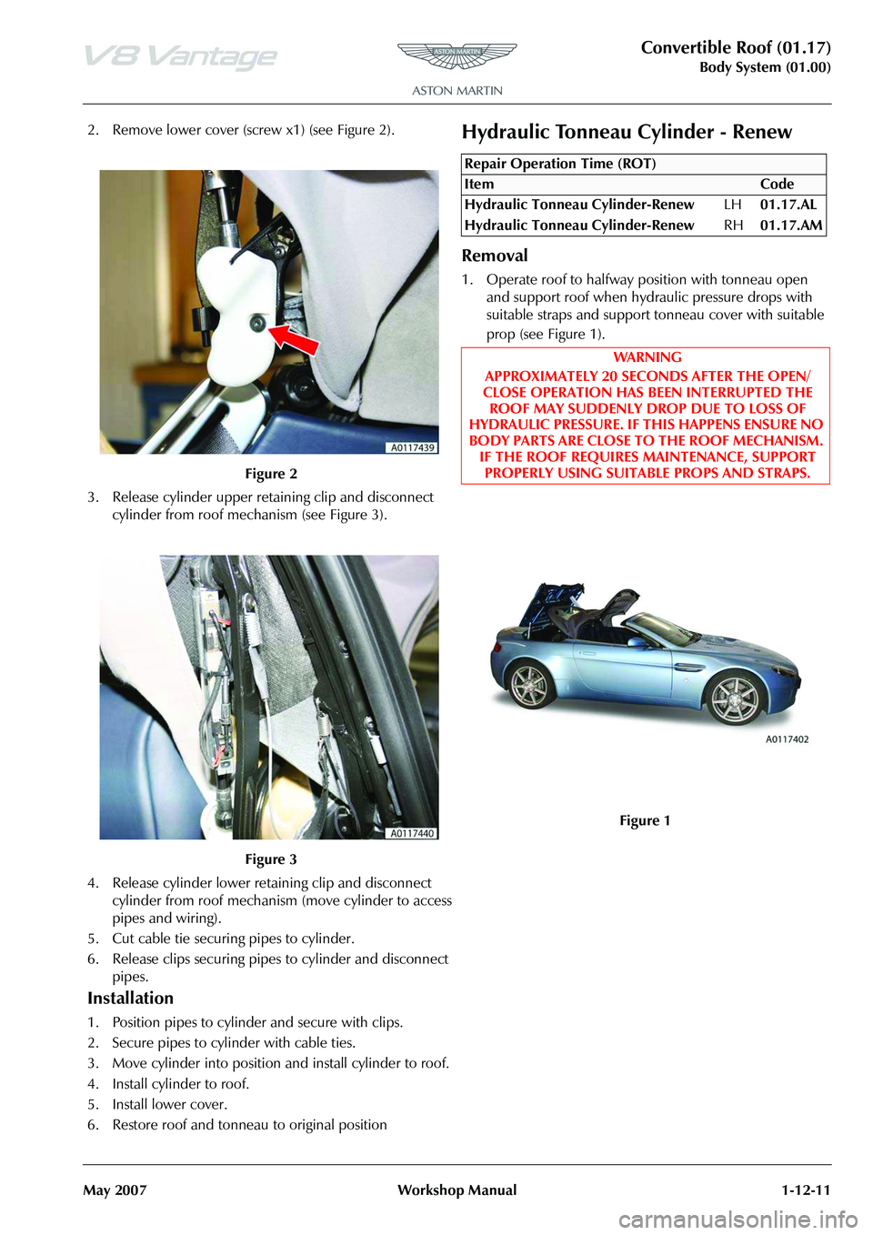
2. Remove lower cover (scr ew x1) (see Figure 2).
3. Release cylinder upper retaining clip and disconnect cylinder from roof mech anism (see Figure 3).
4. Release cylinder lower retaining clip and disconnect cylinder from roof mechanis m (move cylinder to access
pipes and wiring).
5. Cut cable tie securing pipes to cylinder.
6. Release clips securing pipes to cylinder and disconnect
pipes.
Installation
1. Position pipes to cylinder and secure with clips.
2. Secure pipes to cyli nder with cable ties.
3. Move cylinder into position and install cylinder to roof.
4. Install cylinder to roof.
5. Install lower cover.
6. Restore roof and tonneau to original position
Hydraulic Tonneau Cylinder - Renew
Removal
1. Operate roof to halfway position with tonneau open and support roof when hydraulic pressure drops with
suitable straps and support tonneau cover with suitable
prop (see Figure 1).
Figure 2
Figure 3
Repair Operation Time (ROT)
Page 150 of 947
Convertible Roof (01.17)
Body System (01.00)1-12-12 Workshop Manual May 2007
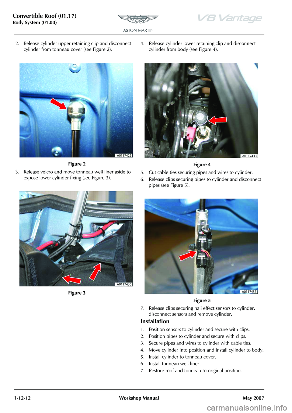
2. Release cylinder upper retaining clip and disconnect cylinder from tonneau cover (see Figure 2).
3. Release velcro and move tonneau well liner aside to expose lower cylinder fixing (see Figure 3). 4. Release cylinder lower retaining clip and disconnect
cylinder from body (see Figure 4).
5. Cut cable ties securing pipes and wires to cylinder.
6. Release clips securing pipes to cylinder and disconnect pipes (see Figure 5).
7. Release clips securing hall effect sensors to cylinder, disconnect sensors and remove cylinder.
Installation
1. Position sensors to cylind er and secure with clips.
2. Position pipes to cylinder and secure with clips.
3. Secure pipes and wires to cylinder with cable ties.
4. Move cylinder into position and install cylinder to body.
5. Install cylinder to tonneau cover.
6. Install tonneau well liner.
7. Restore roof and tonneau to original position.
Figure 2
Figure 3
Figure 4
Figure 5
Page 151 of 947

Convertible Roof (01.17)
Body System (01.00)
May 2007 Workshop Manual 1-12-13
Convertible Top ECU - Renew
Removal
1. Remove wheel arch liner rear RH (see Workshop Manual procedure 01.02.HB Wheel Arch Liner - Rear -
RH - Renew).
2. Remove bolts (x4) securing ECU mounting plate and release from body (see Figure 1).
3. Disconnect multiplugs (x3) from ECU (see Figure 2).
4 . R e m o v e E C U f r o m m o u n t i n g p l a t e ( n u t s x 2 ) .
Installation
1. Install ECU to mounting plate.
2. Connect multiplugs (x3) to ECU. 3. Position mounting plate to body and install securing
bolts.
4. Remove wheel arch liner rear RH (see Workshop Manual procedure 01.02.HB Wheel Arch Liner - Rear -
RH - Renew).
Hydraulic Pump - Renew
Removal
1. Operate roof to halfway position with tonneau open and support roof when hydraulic pressure drops with
suitable straps and support tonneau cover with suitable
prop (see Figure 1).
Repair Operation Time (ROT)
Repair Operation Time (ROT)
Page 152 of 947

Convertible Roof (01.17)
Body System (01.00)1-12-14 Workshop Manual May 2007
2. Remove trim clip and releas e tonneau lining stiffening
rod (see Figure 2).
3. Release velcro and move tonneau well liner aside to expose lower cylinder fixing and motor casing.
4. Release cylinder lower retaining clip and disconnect tonneau cylinder from body (see Figure 3). 5. Remove cylinder pivot bracket from body (bolts x3) (see
Figure 4).
6. Release pump and casing from under tonneau body side (see Figure 5).
Figure 2
Figure 3
Figure 4
Figure 5
Page 153 of 947

Convertible Roof (01.17)
Body System (01.00)
May 2007 Workshop Manual 1-12-15
7. Release velcro around pump casing and remove casing (see Figure 6).
8. Disconnect pump multiplug (see Figure 7). 9. Disconnect pump multiplug (see Figure 8).
10. Remove end cover (locating tabs x2).
11. Disconnect pump lucar conne
ctors (x2) (see Figure 9).
Figure 6
Figure 7
Figure 8
Figure 9
Page 154 of 947
Convertible Roof (01.17)
Body System (01.00)1-12-16 Workshop Manual May 2007
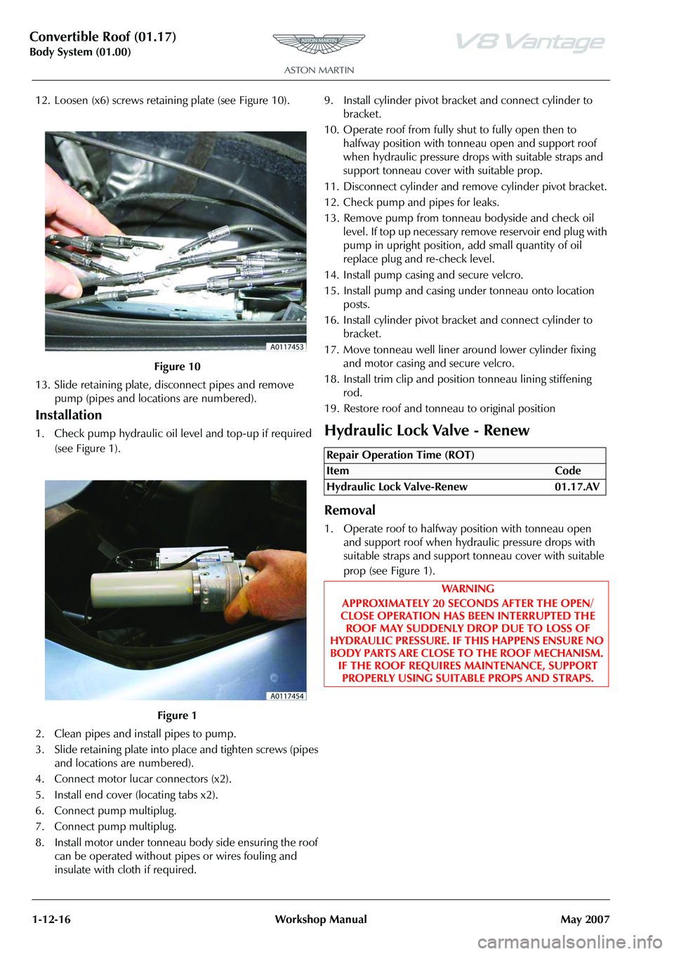
12. Loosen (x6) screws retain ing plate (see Figure 10).
13. Slide retaining plate, disconnect pipes and remove pump (pipes and locations are numbered).
Installation
1. Check pump hydraulic oil le vel and top-up if required
(see Figure 1).
2. Clean pipes and install pipes to pump.
3. Slide retaining plate into place and tighten screws (pipes and locations are numbered).
4. Connect motor lucar connectors (x2).
5. Install end cover (locating tabs x2).
6. Connect pump multiplug.
7. Connect pump multiplug.
8. Install motor under tonneau body side ensuring the roof can be operated without pipes or wires fouling and
insulate with cloth if required. 9. Install cylinder pivot bracket and connect cylinder to
bracket.
10. Operate roof from fully shut to fully open then to halfway position with tonneau open and support roof
when hydraulic pressure drop s with suitable straps and
support tonneau cover with suitable prop.
11. Disconnect cylinder and remove cylinder pivot bracket.
12. Check pump and pipes for leaks.
13. Remove pump from tonneau bodyside and check oil level. If top up necessary remove reservoir end plug with
pump in upright position, add small quantity of oil
replace plug and re-check level.
14. Install pump casing and secure velcro.
15. Install pump and casing under tonneau onto location posts.
16. Install cylinder pivot bracket and connect cylinder to bracket.
17. Move tonneau well liner arou nd lower cylinder fixing
and motor casing and secure velcro.
18. Install trim clip and positi on tonneau lining stiffening
rod.
19. Restore roof and tonneau to original positionHydraulic Lock Valve - Renew
Removal
1. Operate roof to halfway position with tonneau open and support roof when hydraulic pressure drops with
suitable straps and support tonneau cover with suitable
prop (see Figure 1).
Figure 10
Figure 1
Repair Operation Time (ROT)
ItemCode
Hydraulic Lock Valve-Renew 01.17.AV
WAR NI NG
APPROXIMATELY 20 SECONDS AFTER THE OPEN/
CLOSE OPERATION HAS BEEN INTERRUPTED THE ROOF MAY SUDDENLY DROP DUE TO LOSS OF
HYDRAULIC PRESSURE. IF THIS HAPPENS ENSURE NO
BODY PARTS ARE CLOSE TO THE ROOF MECHANISM. IF THE ROOF REQUIRES MAINTENANCE, SUPPORT
PROPERLY USING SUITABLE PROPS AND STRAPS.
Page 155 of 947
Convertible Roof (01.17)
Body System (01.00)
May 2007 Workshop Manual 1-12-17
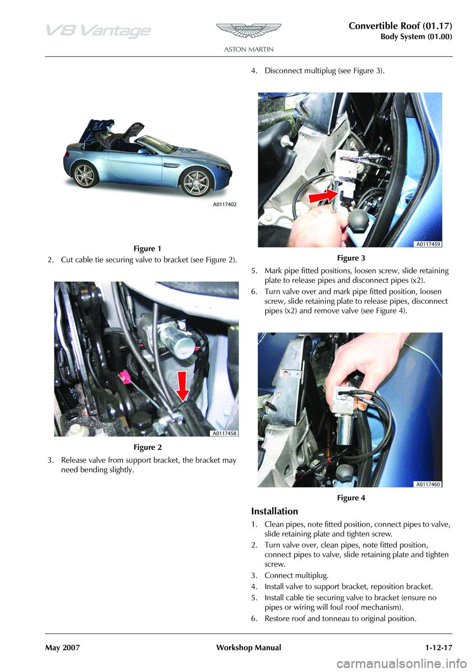
2. Cut cable tie securing valve to bracket (see Figure 2).
3. Release valve from support bracket, the bracket may need bending slightly. 4. Disconnect multiplug (see Figure 3).
5. Mark pipe fitted positions, loosen screw, slide retaining
plate to release pipes and disconnect pipes (x2).
6. Turn valve over and mark pipe fitted position, loosen screw, slide retaining plate to release pipes, disconnect
pipes (x2) and remove valve (see Figure 4).
Installation
1. Clean pipes, note fitted posi tion, connect pipes to valve,
slide retaining plate and tighten screw.
2. Turn valve over, clean pipes, note fitted position, connect pipes to valve, slide retaining plate and tighten
screw.
3. Connect multiplug.
4. Install valve to support br acket, reposition bracket.
5. Install cable tie securing valve to bracket (ensure no pipes or wiring will foul roof mechanism).
6. Restore roof and tonneau to original position.
Figure 1
Figure 2
Figure 3
Figure 4
Page 156 of 947
Convertible Roof (01.17)
Body System (01.00)1-12-18 Workshop Manual May 2007
RH/LH Front Cantrail Seal - Spare Part -
Renew
Removal
1. Remove header trim (see Workshop Manual procedure 01.05.BB Panel Assembly - Header - Renew).
2. Mark position of nuts (x2) to aid installation.
3. Remove nuts (x2) secu ring seal holder to hood
mechanism and remove seal from holder.
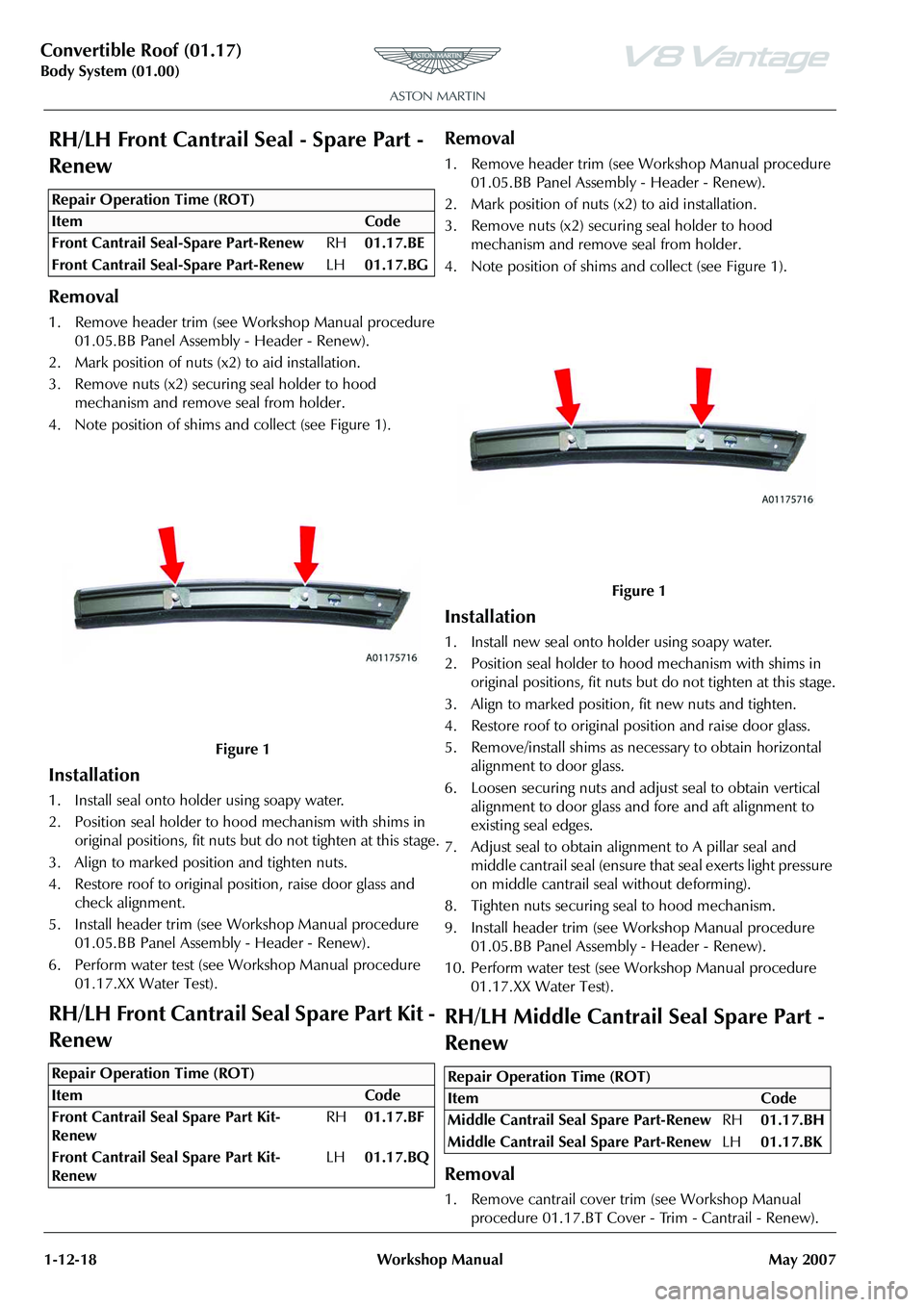
4. Note position of shims and collect (see Figure 1).
Installation
1. Install seal onto holder using soapy water.
2. Position seal holder to hood mechanism with shims in original positions, fit nuts but do not tighten at this stage.
3. Align to marked position and tighten nuts.
4. Restore roof to original position, raise door glass and check alignment.
5. Install header trim (see Workshop Manual procedure 01.05.BB Panel Assembly - Header - Renew).
6. Perform water test (see Workshop Manual procedure
01.17.XX Water Test).
RH/LH Front Cantrail Seal Spare Part Kit -
Renew
Removal
1. Remove header trim (see Workshop Manual procedure 01.05.BB Panel Assembly - Header - Renew).
2. Mark position of nuts (x2) to aid installation.
3. Remove nuts (x2) secu ring seal holder to hood
mechanism and remove seal from holder.
4. Note position of shims and collect (see Figure 1).
Installation
1. Install new seal onto holder using soapy water.
2. Position seal holder to hood mechanism with shims in
original positions, fit nuts but do not tighten at this stage.
3. Align to marked position, fit new nuts and tighten.
4. Restore roof to original position and raise door glass.
5. Remove/install shims as necessary to obtain horizontal alignment to door glass.
6. Loosen securing nuts and adju st seal to obtain vertical
alignment to door glass and fore and aft alignment to
existing seal edges.
7. Adjust seal to obtain alignment to A pillar seal and middle cantrail seal (ensure that seal exerts light pressure
on middle cantrail seal without deforming).
8. Tighten nuts securing seal to hood mechanism.
9. Install header trim (see Workshop Manual procedure 01.05.BB Panel Assembly - Header - Renew).
10. Perform water test (see Workshop Manual procedure 01.17.XX Water Test).
RH/LH Middle Cantrail Seal Spare Part -
Renew
Removal
1. Remove cantrail cover trim (see Workshop Manual procedure 01.17.BT Cover - Trim - Cantrail - Renew).
Repair Operation Time (ROT)
Repair Operation Time (ROT)
Figure 1
Repair Operation Time (ROT)
ItemCode
Middle Cantrail Se al Spare Part-Renew RH01.17.BH
Middle Cantrail Se al Spare Part-Renew LH01.17.BK
Page 157 of 947
Convertible Roof (01.17)
Body System (01.00)
May 2007 Workshop Manual 1-12-19
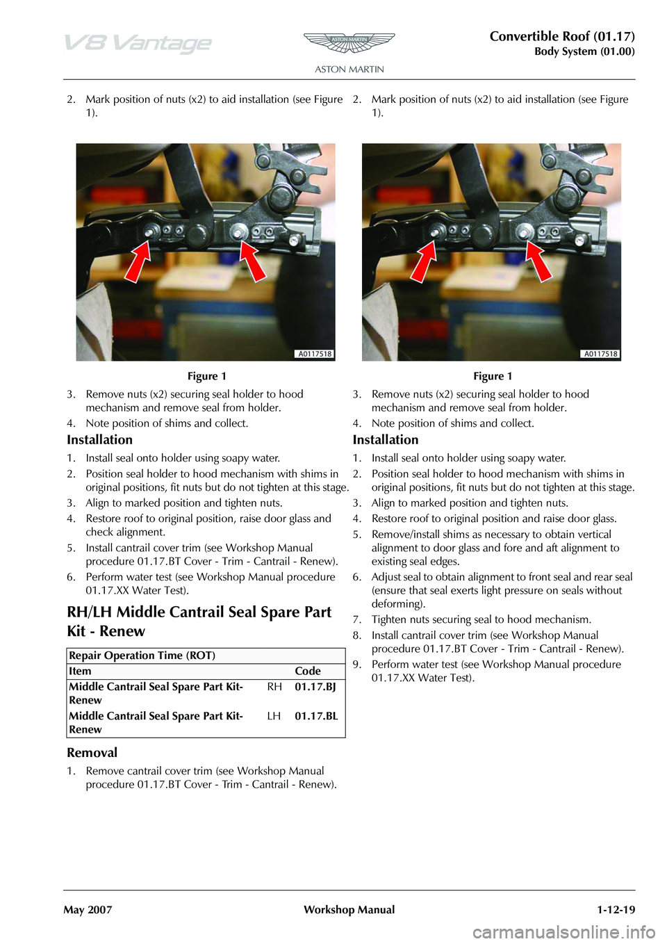
2. Mark position of nuts (x2) to aid installation (see Figure
1).
3. Remove nuts (x2) securing seal holder to hood mechanism and remove seal from holder.
4. Note position of shims and collect.
Installation
1. Install seal onto holder using soapy water.
2. Position seal holder to hood mechanism with shims in original positions, fit nuts but do not tighten at this stage.
3. Align to marked position and tighten nuts.
4. Restore roof to original position, raise door glass and check alignment.
5. Install cantrail cover tr im (see Workshop Manual
procedure 01.17.BT Cover - Trim - Cantrail - Renew).
6. Perform water test (see Workshop Manual procedure 01.17.XX Water Test).
RH/LH Middle Cantrail Seal Spare Part
Kit - Renew
Removal
1. Remove cantrail cover trim (see Workshop Manual procedure 01.17.BT Cover - Trim - Cantrail - Renew). 2. Mark position of nuts (x2) to aid installation (see Figure
1).
3. Remove nuts (x2) securing seal holder to hood mechanism and remove seal from holder.
4. Note position of shims and collect.
Installation
1. Install seal onto holder using soapy water.
2. Position seal holder to hood mechanism with shims in original positions, fit nuts bu t do not tighten at this stage.
3. Align to marked position and tighten nuts.
4. Restore roof to original position and raise door glass.
5. Remove/install shims as nece ssary to obtain vertical
alignment to door glass and fore and aft alignment to
existing seal edges.
6. Adjust seal to obtain alignment to front seal and rear seal (ensure that seal exerts light pressure on seals without
deforming).
7. Tighten nuts securing seal to hood mechanism.
8. Install cantrail cover trim (see Workshop Manual procedure 01.17.BT Cover - Trim - Cantrail - Renew).
9. Perform water test (see Workshop Manual procedure 01.17.XX Water Test).
Figure 1
Repair Operation Time (ROT)
Figure 1
Page 158 of 947
Convertible Roof (01.17)
Body System (01.00)1-12-20 Workshop Manual May 2007
Rear Seal Spare Part Assembly Kit -
Renew
Removal
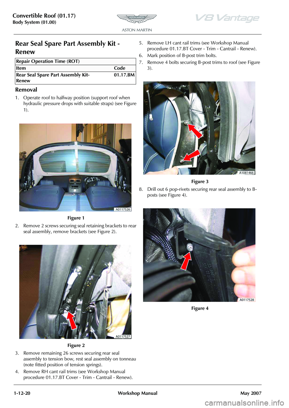
1. Operate roof to halfway position (support roof when hydraulic pressure drops with suitable straps) (see Figure
1).
2. Remove 2 screws securing seal retaining brackets to rear seal assembly, remove brackets (see Figure 2).
3. Remove remaining 26 screws securing rear seal assembly to tension bow, rest seal assembly on tonneau
(note fitted position of tension springs).
4. Remove RH cant rail trims (see Workshop Manual procedure 01.17.BT Cover - Trim - Cantrail - Renew). 5. Remove LH cant rail trims (see Workshop Manual
procedure 01.17.BT Cover - Trim - Cantrail - Renew).
6. Mark position of B-post trim bolts.
7. Remove 4 bolts securing B-post trims to roof (see Figure 3).
8. Drill out 6 pop-rivets securi ng rear seal assembly to B-
posts (see Figure 4).
Repair Operation Time (ROT)
Figure 3
Figure 4