AUDI A4 2017 Owner's Manual
Manufacturer: AUDI, Model Year: 2017, Model line: A4, Model: AUDI A4 2017Pages: 386, PDF Size: 96.32 MB
Page 21 of 386
that was p laced on hold st ays on ho ld and can be
taken
off ho ld wit h Resume.
Conferen ce* :
a call on ho ld and up to five ac tive
p art ies ( depend ing o n the ce ll phone serv ice p ro
vider) can be added to a conference call . To ma ke
an ad ditional call, put all part ici pants i n the c ur
rent confe rence call on ho ld usin g
Hold*. By
p ressing the left cont rol b utton, you can make
addit io nal calls from t he d irectory o r the call list .
Resume * takes all part ies off hold .
(D Tips
-The telephone functions can only be con
troll ed w it h the multifunction stee ring
whee l if the te lepho ne e qui pme nt was in
stalled
at the f actory.
- The telephone functions depend on the cell
p hone and whethe r th ey a re s up porte d by
you r ce ll phone servic e prov ider or not.
- The
Call waiting * function must be activa t
ed in your c ell phone and in the MMI to be
a lert ed to an inco ming call dur ing an act ive
call
9 pa ge 1 70. Th e call options d epend
on t he ce ll p hone and s ervice pr ovider. Y ou
c an obtain m ore in for mat ion from your c ell
p hone service provi der.
Navigation
Applies to: ve hicles with navigation system
R equ irement: a dest ination must be entered
¢
page 187 and the route g uidance must be
started .
~ Press the l<1 1>I butto n repeated ly unt il the Navi-
gatio n tab is displayed .
~ Press the left contro l button ¢ page 13.
Dependin g on vehicle equipmen t, the following
fu nctions may be avai lab le in t he dr ive r informa
tion system.
- Displaying navigation during active route
guidance :
select and confi rm Map* / Street
view* or Arrow view*.
- Showing the map when route guidance is not
active* :
select and co nfirm Map *.
- Accessing last destinations :
select and confirm
Last destinations > the desired destina tion.
Cockpit overview
- Accessing favorites* :
select and confirm Favor
ites
> the desired destination.
- Starting route guidance to the stored home
address :
se lect and confir m Cancel route guid
ance
i f necessa ry and t hen Home address .
If you h ave not start ed any rou te g uid ance, a
c om pass (analo g instr ume nt cl us ter) or the ar
row view (monoch rome instrument cluster) is
displayed depending on the e quipment. Th e map
is d isp layed in the Aud i virtua l coc kpit *.
Canceling active route guidance
-Sele ct: r ig ht con trol butto n > Cancel route
guidance
Additional settings
- Select: r igh t con trol button > desired entry .
Depending on the function se lected, t he follow
i ng additional settings may be possible:
- Map dis p lay ¢
page 198
-Map colo rs ¢ page 198
- Map orien tati on ¢ page 1 98
- Auto mati c zo om ¢ page 1 98
Nav igation view with route guidance
started
Appl ies to : vehicles wit h navigat ion system and Aud i v irtual
cockp it
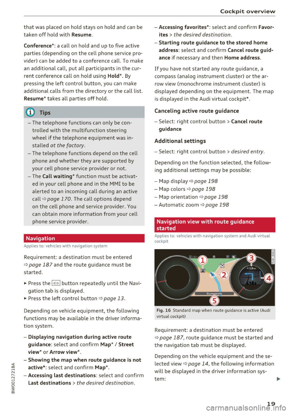
Fig. 16 Sta ndard map w he n ro ute guida nce is active (A udi
vi rtua l cockpit)
Requireme nt: a dest ina tion must be entered
¢
pag e 18 7, ro ute guidance must be sta rted and
t h e nav iga tion tab m ust be displayed .
Depen ding on the vehicle equipment a nd t hese
lected view¢
page 14, the follow ing information
will be di splayed in the d river info rmatio n sys -
tem:
~
19
Page 22 of 386
Cockpit overv iew
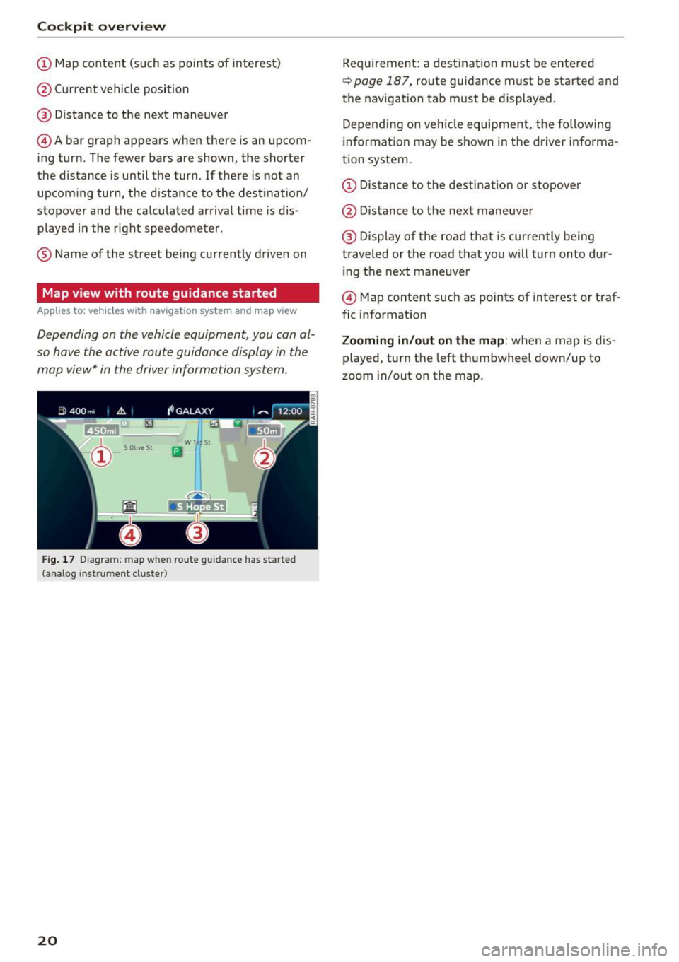
CD Map content (such as points of interest)
@ Current vehicle position
@ Distance to the next maneuver
© Abar graph appears when there is an upcom
ing turn. The fewer bars are shown, the shorter
the distance is until the turn. If there is not an
upcoming turn, the distance to the dest ination/
stopover and the calculated arrival time is dis
p layed i n the right speedometer .
® Name of the street being currently drive n on
Map view with route guidance started
Appl ies to: ve hicles with navigation system an d ma p view
Depending on the vehicle equipment, you can al
so have the active route guidance display in the
map view* in the driver information system.
w l St
Iii
F ig. 1 7 Diagram: map w hen ro ute guidance has started
(analog instrument cluste r)
20
Requirement: a destinat ion m ust be entered
~ page 187, route guidance must be started and
the nav igation tab must be displayed.
Depend ing o n veh icle equipment, the following
information may be shown in the driver info rma
tion system.
CD Dis tance to the destinat io n or sto pove r
@ Distance to t he next maneuve r
@ Display of the road that is currently being
traveled or the road that you will turn onto dur i ng the next maneuver
© Map content such as po ints of interest o r traf
fic information
Zooming in/out on the map : when a map is dis
played, turn the left th umbwhee l down/up to
zoom in/out on the map .
Page 23 of 386
Cockpit overview
Street view with route guidance started
Applies to: vehicles with nav igation system and street view
Depending on the vehicle equipment, the active route guidance will be displayed in the street view* in
the driver information system .
®
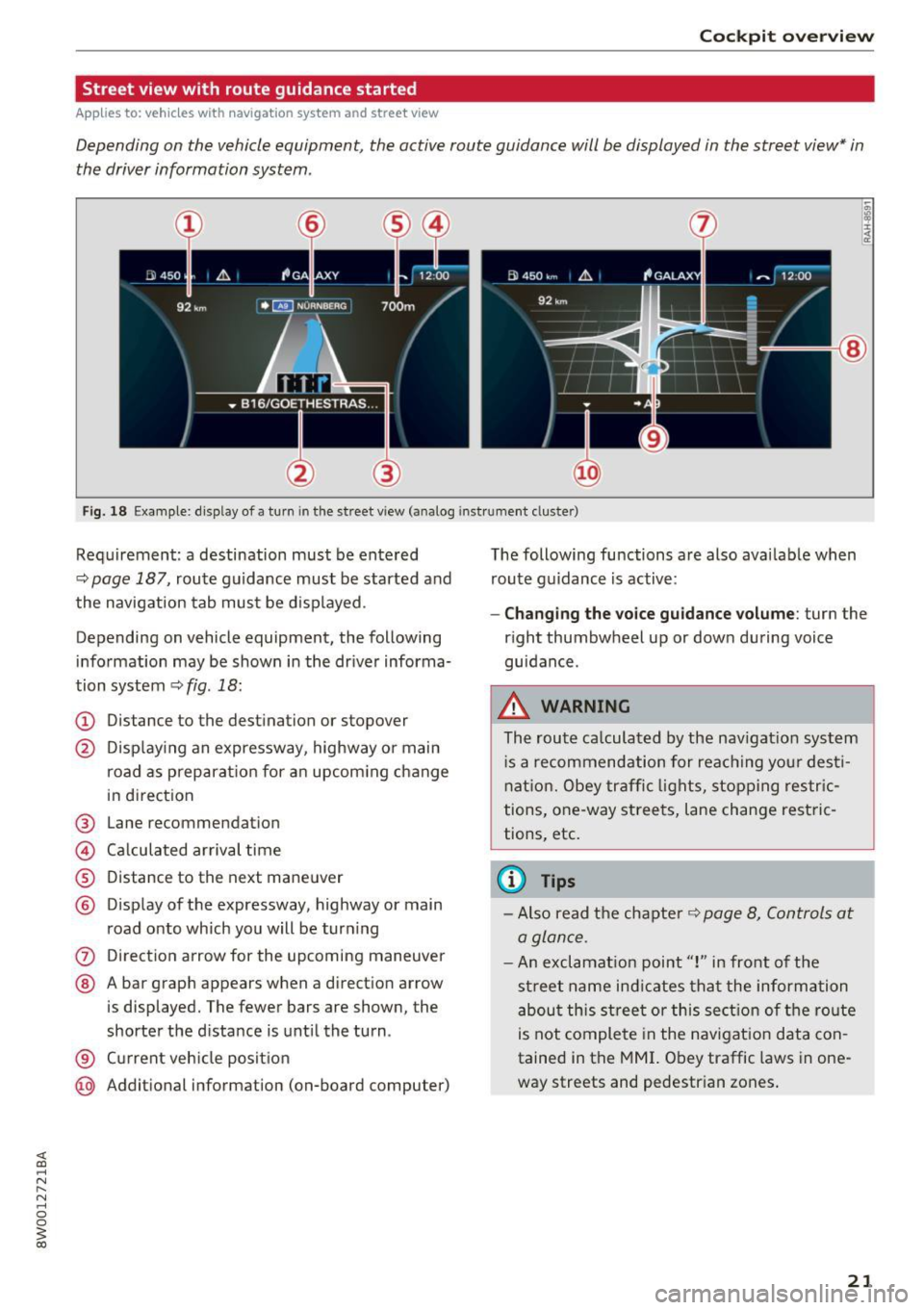
Fig. 18 Example: display of a turn in the street v iew (a nalog instr ument clus te r)
Requirement: a destination must be entered
¢page 187, route gu idance must be started and
the navigation tab must be displayed .
Depending on vehicle equipment, the following
information may be shown in the dr iver informa
tion system ¢
fig. 18:
(D Distance to the destination or stopover
@ Displaying an expressway, highway or main
road as preparat ion for an upcom ing change
in direction
® Lane recommendation
@ Ca lculated arrival time
® Distance to the next maneuver
@ Display of the expressway, highway or main
road onto which you will be turn ing
0 Direction arrow for the upcoming maneuver
@ A bar graph appears when a direction arrow
is displayed. The fewer bars are shown, the
shorter the distance is until the turn .
® Current veh icle position
@ Additional information (on-board computer) The
following functions are also avai lable when
route guidance is active :
-Changing the voice guidance volume: turn the
r ight thumbwheel up or down during voice
gu idance .
.8, WARNING
-
The route ca lculated by the nav igat ion system
i s a recommendation for reaching your dest i
nation. Obey traffic lights, stopping restric
tions, one-way streets, lane change restric
tions, etc.
(0 Tips
- Also read the chapter ~ page 8, Controls at
a glan ce .
- An exclamat ion point" !" in front of the
street name indicat es that the information
about this street or this section of the route
is not complete in the navigation data con
tained in the MMI. Obey traffic laws in one
way streets and pedestrian zones .
21
Page 24 of 386
Cockpit overv iew
Arrow view with route guidance started
Applies to: ve hicles w ith navigat ion system and arrow view
Depending on the vehicle equipment, the active route guidance will be displayed in the arrow view* in
the driver information system .
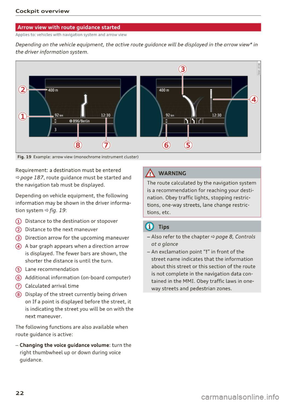
Fig. 19 Example: ar row view (monoc hrome instrument cluster)
Req uirement: a destination must be entered
~ page 187, route g uidance must be started and
the navigation tab mus t be disp layed.
Depending on vehicle equipment, the following
info rmation may be shown in the dr iver informa
tion system
~ fig . 19:
(D Distance to the destinat ion or stopover
@ Distance to the next maneuve r
® Direction arrow for the upcoming maneuver
© A bar graph appears when a direct ion arrow
i s displayed . The fewer bars are shown, the
shorter the d istance is unt il the turn .
® Lane recommendation
@ Addit ional information (on -board computer)
0 Ca lcula ted arrival time
@ Disp lay of the street currently being driven
on If a point is displayed before the street , it
is indicating the street you will be o n with the
next maneuver .
The fo llowing funct ions are a lso available when
route guidance is act ive:
- Changing the voice guidance volume : turn the
right thumbwhee l up o r down during vo ice
guidance.
22
@
@
_&, WARNING
The route calculated by the nav igat ion sys tem
is a recommendation for reaching your desti
n ation . Obey traffic lights, stopping restric
tions, one-way streets, lane change restric
tions, etc.
(D Tips
- Also refer to the chapter ~ page 8, Controls
ata glance
- An exclamation point"!" in front o f the
street name indicates that the information about this street or th is section of the ro ute
is not complete in the navigat ion data con
tained in the MMI. Obey traffic laws in one
way streets and pedestr ian zo nes.
Page 25 of 386
Head-up Display
Applies to: vehicles with Head-up Display
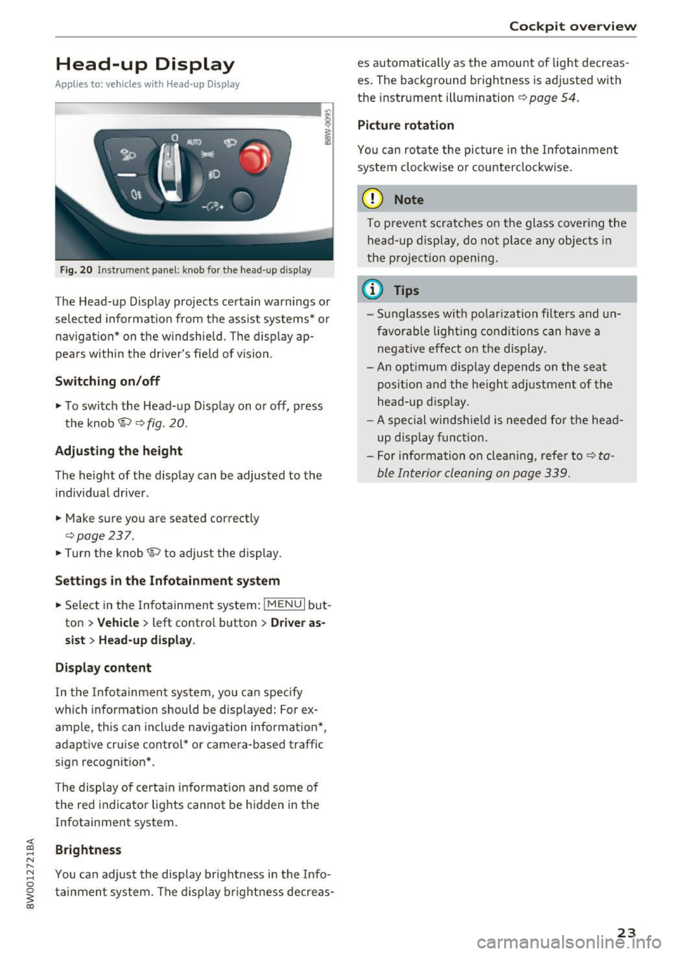
Fig. 20 Instrument panel : knob for the head-up display
The Head-up Display projects certain warnings or
selected information from the assist systems* or
navigation* on the windshield. The d isplay ap
pears within the drive r's field of vision.
Switching on/off
• To switch the Head-up Display on or off, press
the knob
1;) ¢ fig . 20.
Adjusting the height
The height of the display can be adjusted to the
individual driver.
• Make sure you are seated correctly
¢ page 237.
• Turn the knob 1;) to adjust the display.
Settings in the Infotainment system
• Se lect in the Infotainment system: !MENU I but
ton
> Vehicle > left contro l button > Driver as
sist
> Head-up display .
Display content
In the Infotainment system, yo u can specify
which information should be displayed: For ex
ample, this can include navigation information*,
adaptive cruise control* or camera-based traffic
sign recognit ion* .
The display of certain information and some of the red indicator lights cannot be hidden in the
Infotainment system.
Brightness
You can adjust the display brightness in the Info
tainment system. The display brightness decreas-
Cockpit overview
es automatically as the amount of light decreas
es. The background brightness is adjusted with
the instrument illumination ¢
page 54.
Picture rotation
You can rotate the picture in the Infotainment
system clockwise o r counterclockwise.
(D Note
To prevent scratches on the glass cover ing the
head-up display, do not place any objects in
the pro jection opening.
(D Tips
- Sunglasses with polarization filters and un
favorable lighting conditions can have a
negative effect on the display .
- An opt imum disp lay depends on the seat
posi tion and the heigh t adjustment of the
head -up disp lay.
- A special windshie ld is needed for the head
up display function.
- For information on cleaning, refer to¢
ta
ble Interior cleaning on page 339.
23
Page 26 of 386
Cockpit overview
Camera-based traffic
sign recognition
Description
Applies to: vehicles with camera-based traffic sign recogn i
tion
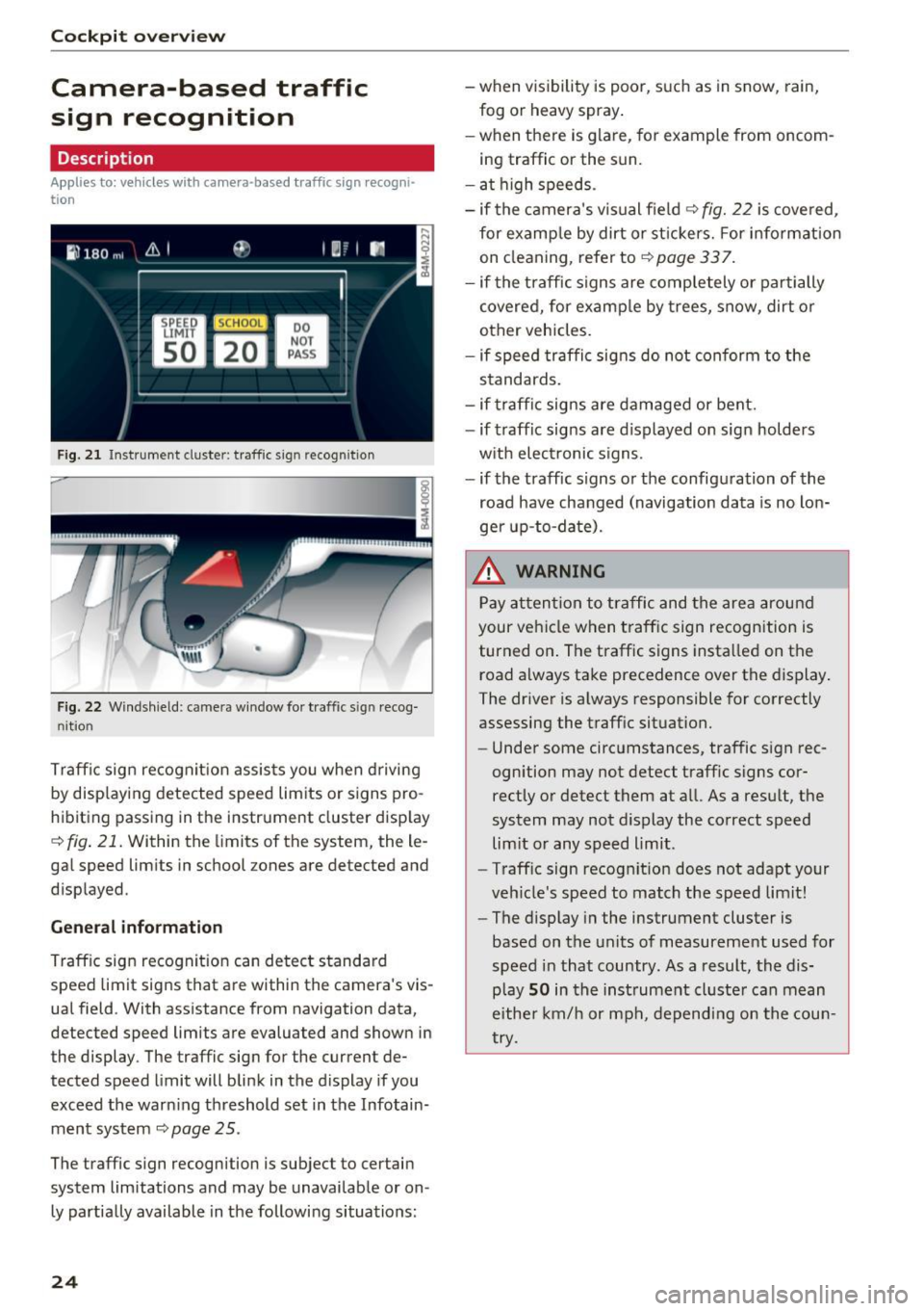
F ig. 21 Instrument cluster: traffic sign recognition
Fig. 22 Windshield: camera window fo r tra ffic sign recog
nit ion
Traffic sign recognit ion assists you when driving
by displaying detected speed limits or signs pro
hibiting passing in the instrument cluster disp lay
~fig . 21. Within the limits of the system, the le
gal speed limits in school zones are detected and
displayed.
General information
Traffic sign recognit ion can detect standard
speed limit signs that are within the camera's vis
ual field. With assistance from navigation data,
detected speed limits are evaluated and shown in
the display. The traffic sign for the current de
tected speed limit will blink in the display if you
exceed the warning threshold set in the Infotain ment system
~ page 2 5 .
The traffic sign recognition is subject to certain
system limitations and may be unavailable or on
ly partially available in the following situations:
24
-when visibility is poor, such as in snow, rain,
fog or heavy spray .
-when there is glare, for example from oncom
ing traffic or the sun.
- at high speeds.
- if the camera's visual field
~ fig. 22 is covered,
for examp le by dirt or st ickers. For info rmation
on cleaning, refer to
c::> page 33 7.
- if the traffic signs are completely or partially
covered, for examp le by trees, snow, dirt or
other vehicles.
- if speed traffic signs do not conform to the
standards.
- if traffic signs are damaged or bent.
- if traffic signs are d isplayed on sign holders
w ith electronic signs.
- if the traffic signs or the configuration of the
road have changed (navigation data is no lon
ger up-to-date) .
.&_ WARNING
Pay attention to traffic and the area around
your vehicle when traffic sign recognition is
turned on . The traffic signs installed on the
road always take precedence over the display.
The driver is always responsible for correctly
assessing the traff ic situation.
- Under some circumstances, traffic sign rec
ognition may not detect traffic signs cor
rectly or detect them at all. As a result, the
system may not display the correct speed
lim it or any speed limit.
- Traff ic sign recognit ion does not adapt your
veh icle's speed to match the speed limit!
- The display in the instrument cluster is
based on the units of measurement used for
speed in that country. As a result, the dis
play
SO in the instrument cluster can mean
eithe r km/h or mph, depending on the coun
try.
-
Page 27 of 386
Operation
Applies to: vehicles with camera -based traffic sign recogni
tion
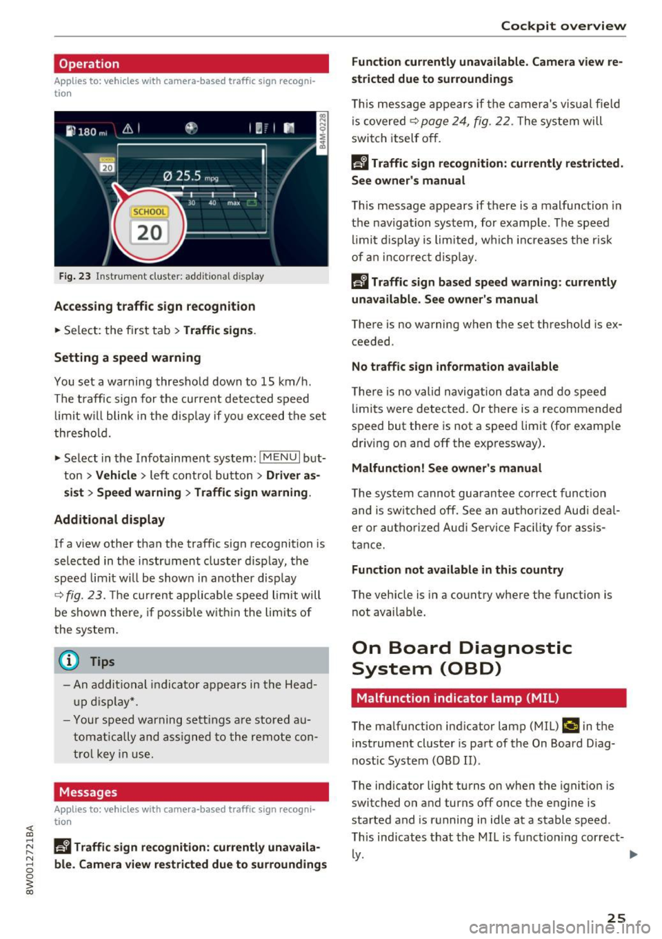
F ig. 23 Instr ume nt cluster: add itiona l d isplay
Accessing traffic sign recognition
.. Se lect: the f irst tab> Traffic signs .
Setting a speed warning
You set a warning thresho ld down to 15 km/ h.
The traffic s ign for the curre nt detec ted speed
limit w ill blink in the d isp lay if yo u excee d the set
thresho ld.
.,. Select in the Info tainment sys tem:
!MEN U I but
ton >
Vehicle > left contro l bu tton > Driver as
s ist > Speed warning
> Traffic sign warning .
Additional display
If a v iew othe r th an the traffic sign recognition is
se lec ted in t he i nstr ument cluster d isp lay, the
speed limit w ill be shown in another disp lay
~ fig. 23. The cur rent applicable speed limit will
be shown the re, if pos sibl e w it hi n the lim its of
the system.
{t) Tips
- An a ddi tio nal i ndic a tor a pp ears in the Head
up disp lay*.
- Y our spe ed w arning s ettin gs a re stor ed a u
t om atica lly an d assigned to the rem ote con
t ro l key in us e.
Messages
Applies to: vehicles with camera-based traffic sign recogni
tion
~ Ii Traffic sign recognition: currently unavaila
r-1 8 ble_ Camera view restricted due to surroundings
0
~ co
Cockpit overview
Function currently unavailable. Camera view re
stricted due to surroundings
T hi s mess age app ea rs if th e ca mera 's v is u al fiel d
is covere d~
page 24 , fig. 22 . The system will
switch itself o ff.
Ii Traffic sign recognition: currently restricted.
See owner's manual
T h is message appears if there is a mal function in
t h e nav igation system, for examp le . Th e speed
li mi t d isplay is lim ite d, w hich incr eases the r is k
of an in cor re ct displa y.
la Traffic sign based speed warning : currently
unavailable. See owner's manual
There is no wa rning when t he set t hreshold is e x
ceeded .
No traffic sign information available
The re is no valid navig ation d ata and do speed
li mits were detec ted. Or th ere is a recommende d
s p eed but there is not a speed limit (for examp le
dr iv ing on and off the exp ressway) .
Malfunction! See owner 's manual
T he system canno t gua rantee correct funct ion
and is swi tc hed off. See an a uthoriz e d Au di deal
er o r autho riz e d Au di Servi ce Facili ty for as sis
t ance.
Function not available in this country
The vehicle is in a co untry where the function is
not avai lab le.
On Board Diagnostic
System (OBD)
Malfunction indicator lamp (MIL)
The malfunction ind icator lamp (MIL) ¢;j in the
i nstrument cluste r is par t of the On Board D iag
nost ic System (O BD II) .
The ind icator light turns on when the ignition is
switched on and turns off once the engine is
sta rted and is r unning in id le at a stable speed .
T his ind icates that the MIL is f unction ing cor rec t-
~-~
25
Page 28 of 386
Cockpit overview
If the light does not turn off after starting the
engine
or turns on while driving, this may indi·
cate that there is a malfunction in the eng ine. If
the indicator turns on , the catalytic converter
may be damaged.
Drive
with reduced engine performance (avoid
h ig h speeds for extended periods of time and/ or
fast acce leration) and have the malfunction cor
rected. See an authorized Aud i dealer or author
ized Audi Service Fac ility .
The electronic speed limiter may be faulty if the
indicator light turns on. For additional informa
tion, refer to
¢ page 93, Electronic speed limit
er .
The MIL indicator light may also turn on if the
fuel filler cap is not closed correctly
¢page 298.
On-Board Diagnostics
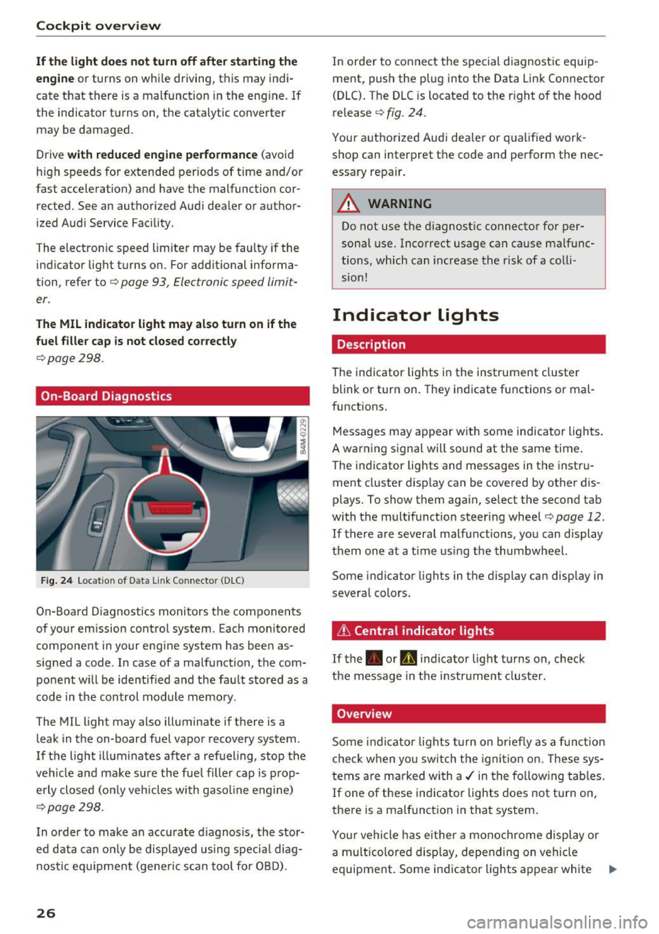
Fig . 24 Locat ion of Data Link Connector (D LC)
On-Board Diagnostics monitors the components
of your emission control system. Each monitored
component in your engine system has been as
signed a code . In case of a malfunction, the com
ponent w ill be identified and the fault stored as a
code in the control module memory.
The MIL light may also illuminate if there is a
leak in the on-board fuel vapor recovery system .
If the light illuminates after a refuel ing, stop the
veh icle and make sure the fue l filler cap is prop
erly closed (on ly vehicles with gasol ine engine)
¢page 298.
In order to make an accurate d iagnosis, the stor
ed data can only be disp layed using specia l diag
nostic equipm ent (ge ne ric scan tool for OBD) .
26
In order to connect the special diagnostic equip
ment, push the plug into the Data Link Connector
(DLC). The DLC is located to the r ight of the hood
release
¢ fig. 24.
Your authorized Audi dea le r or qualified work
shop can interpret the code and perform the nec
essary repair.
_& WARNING
Do not use the diagnostic connector for per
sonal use. Incorrect usage can cause malfunc
tions, which can increase the risk of a colli
sion!
Indicator lights
Description
The indicator lights in the instrument cluster
blink or tur n on. They indicate functions or mal
funct ions.
-
Messages may appear with some indicator lights .
A warning signal will sound at the same time.
The ind icator lights and messages in the instru
ment cluster disp lay can be covered by other dis
plays. To show them again, select the second tab
with the multifunction steering wheel ¢page 12.
If there are several ma lfunctions, you can display
them one at a time using the thumbwheel.
Some indicator lights in the display can display in
several colors.
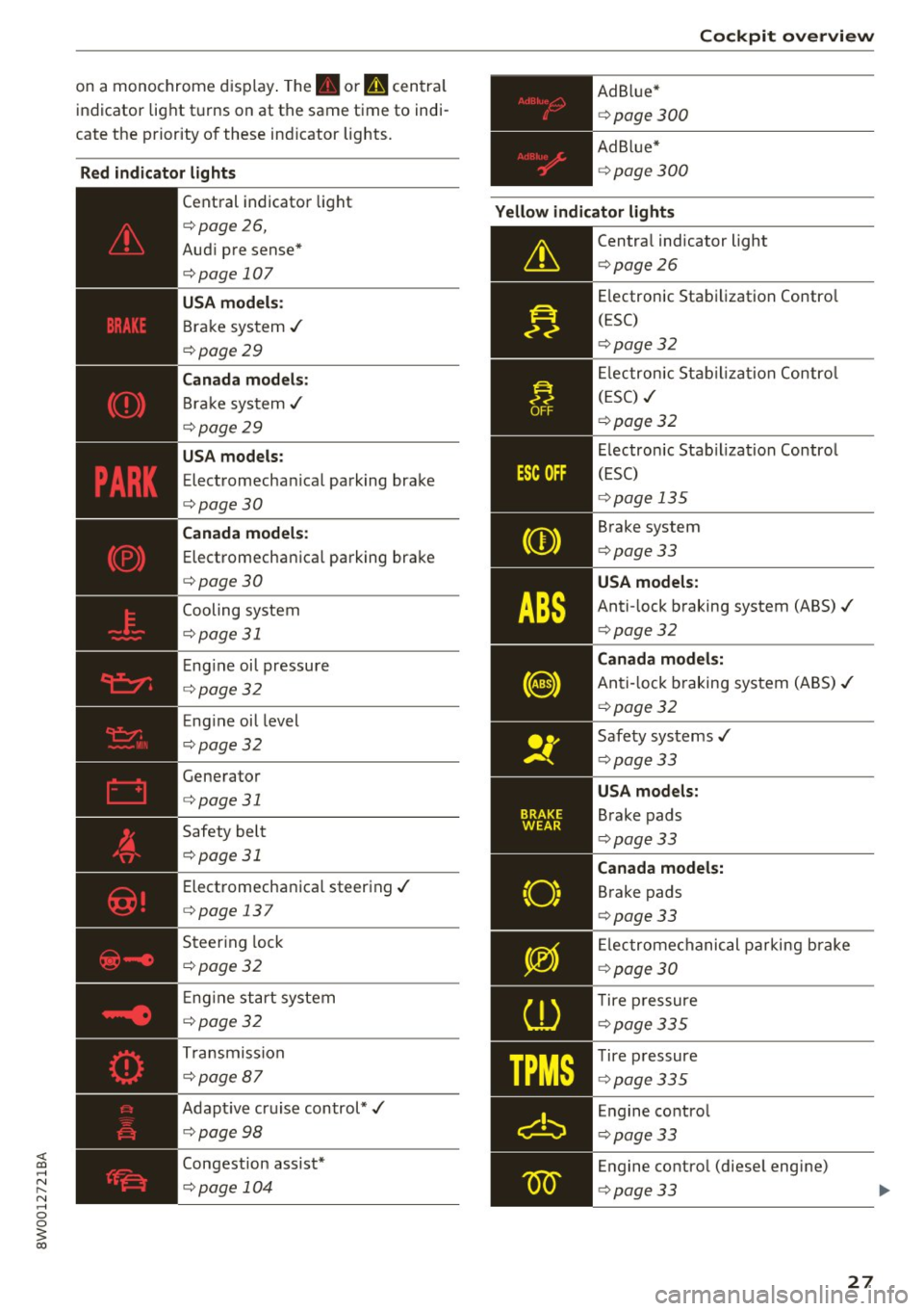
& Central indicator lights
If
the . or Q indicator lig ht turns on, check
the message in the instrument cluster.
Overview
Some indicator lights turn on briefly as a function
check when you switch the ignition on. These sys
tems are marked with a ./ in the fo llow ing tables.
If one of these ind icator lights does not turn on,
there is a malfunction in that system.
Your vehicle has e ither a monoch rome display or
a multicolored display, depending on vehicle
equipment . Some indicator lights appear white
1111-
Page 29 of 386
<( a, .... N ,....
N .... 0 0
3 a,
on a monochrome display. The. or u centra l
indicator light turns on at the same time to indi
cate the priority of these ind icator lights.
Red indicator lights
--------------
Central indicator light
c::> page26,
Aud i pre sense*
c::> page 10 7
USA models:
Brake system ../
c::> page 29
Canada models :
Bra ke system ../
c::> page 29
USA models:
Electromecha nical parking brake
c::> page 30
Canada models:
Electromechanica l parking brake
c::> page30
Cooling system
c::> page 31
E ng ine oi l pressure
c::> page 32
Eng ine oil level
c::> page 32
Generator
c::> page 31
Safety belt
c::> page 31
Electromechanical steering../
c::> page 13 7
Steering lock
c::> page 32
E ng ine start system
c::> page32
Transmission
c::> page 87
Adapt ive cruise control*../
c::> page 98
Congestion assist*
c::> page 104 Cockpit overview
Ad B lue*
c::> page 300
Ad Blue*
c::> page 300
Yellow indicator lights
--------------
Central indicator light
c::> page 26
E lectronic Stabilization Contro l
(ESC)
c::> page 32
El ectronic Stabilization Control
(ESC) ../
c::> page 32
Electronic Stabiliza tion Control
(ESC)
c::> page 13 5
Brake system
c::> page 33
USA models:
Anti-lock braking system (ABS)../
c::> page 32
Canada models:
Anti-lock b raking system (ABS)../
c::> page 32
Safety systems ../
c::> page 33
USA models:
Brake pads
c::> page 33
Canada models:
Brake pads
c::> page 33
El ectromechanical parking brake
c::> page 30
T ire pressure
c::> page 335
Tire pressure
c::> page 335
Engine control
c::> page 33
Engine contro l (diese l engine)
c::> page 33
27
Page 30 of 386
Cockpit over view
28
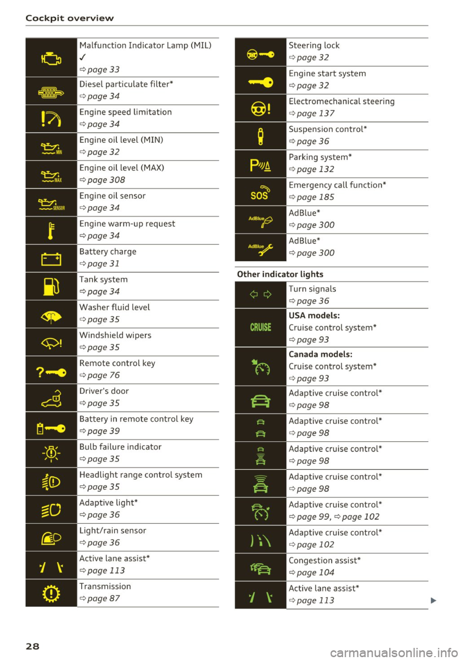
Malfunct ion Indicato r Lamp (MIL)
./
c::>page33
Diesel particulate filter*
c::>page34
Engine speed limitat ion
c::>page34
Engine oil level (MIN)
c::>page32
E ngine oil level (MAX)
c::>page308
Engine oil senso r
c::>page34
Eng ine warm -up request
c::>page34
Battery charge
<=:>page 31
Tank system
c::>page34
Washer fluid level
c::>page35
Windshield wipers
c::>page35
Remote control key
<=:>page 76
Driver's door
c::>page35
Ba ttery in remo te cont rol key
c::>page39
Bulb failure ind icator
c::>page35
H eadlight ra nge control system
c::>page35
Adapt ive lig ht*
c::>page36
Light/rain sensor
c::>page36
Active lane assist*
c::> page 113
Transmission
c::> page87
Steering lock
c::>page32
Engine start system
<=:>page 32
Electromechanical steering
c::> page 13 7
Suspension con trol*
c::> page36
Parking sys tem*
c::> page 132
E mergency call f unct io n*
<=:>page 185
Ad Blue*
c::>page300
Ad Blue*
c::>page300
Other indicator light s
--------------
Turn signals
c::> page36
Cruise contro l system*
<=:> page 93
Canad a model s:
Cruise cont rol sys tem*
<=:> page 93
Adaptive c ruise control *
¢page 98
Adaptive cruise contro l*
<=:> page 98
Adaptive cruise contro l*
¢ page 98
Adaptive c ruise contro l*
¢ page 98
Adaptive c ruise contro l*
¢ page 99, <=:>page 102
Adaptive c ruise cont ro l*
¢ page 102
Conges tion assist*
<=:>page 104
Active lane assist*
c::> page 113