light AUDI A5 2015 Owner´s Manual
[x] Cancel search | Manufacturer: AUDI, Model Year: 2015, Model line: A5, Model: AUDI A5 2015Pages: 264, PDF Size: 66.83 MB
Page 31 of 264
M N
0 loo
rl I.O
"' N
"' rl
the possibility to reset the oi l change schedu le af
ter having performed an oil change according to
Audi specif ications. Select
ICARI function button
> Service interval display > Reset oil change in
terval
or I CAR ! function button > Car systems*
control button > Servicing & checks > Reset oil
change interval.
(D Note
- Only reset the oil change d isp lay when you
have completed an oil change .
- If you d isconnect the battery terminals, no
calculations can be made for the service in
terval display during this t ime and no serv
i ce reminder will appear . Remember that
obse rv in g the proper serv ice intervals is vi
tally impor tant to extending the life of your
vehicle, particularly the engine, and main
taining its value. Even if the mi leage driven
i s low, the maximum period of one year
from one service to the next must not be ex
ceeded.
(D Tips
The information in the Service Reminder re
mains stored even when the veh icle battery is
disconnected.
On Board Diagnostic
System (OBD)
Malfunction Indicator Lamp (MIL)
The Malfunction Indicator Lamp (MIL) ¢-4 in the
instrument cluster is part of the On-Board Diag
nostic (OBD II) system.
The warning/indicator light illuminates when the
ignition is switched on and goes out after the en
gine starts and the idle has stabilized. This indi
cates that the MIL is working properly.
If the light does not go out after the engine is
started, or illuminates while you are driving, a malfunct ion may exist in the engine system. If
the light illuminates, the catalytic converter
could be damaged.
Continue driving
with reduced power (avoiding
sustained high speeds and/or rapid accelerations)
Dri ver information system
and have the condition corrected. Contact your
authorized Audi dea ler.
If t he light illuminates, the electronic speed lim
ite r may also be ma lf u nctioning. For more infor
mation
¢ page 30, Electronic speed limiter .
An improperly closed fuel filler cap may also
cause the MIL light to illuminate ¢
page 188.
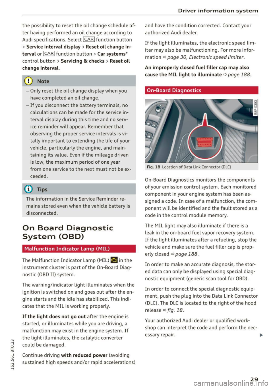
On-Board Diagnostics
Fig. 18 Locat ion of Data Link Connector (DLC)
On-Board D iagnost ics monitors the components
of your emission control system. Each monito red
component in your engine system has been as
signed a code. In case of a malfunction, the com
ponent will be ident ified and the fault stored as a
code in the control module memory.
T he MIL light may also illum inate if there is a
leak in the on-board fuel vapo r recovery system .
If the light illuminates after a refueling, stop the
vehicle and make sure the fuel filler cap is prop
erly closed
¢ page 188.
In order to make an accurate diagnosis, the stor
ed data can only be displayed using special diag
nostic equipment (generic scan tool for OBD).
In order to connect the spec ial diagnostic equip
ment, push the plug into the Data Lin k Connec tor
(DLC). The DLC is located to the right of the hood
release
¢ fig. 18.
Your authorized Audi deale r or qualified work
shop can interpre t the code and perform the nec-
essary repair. .,,.
29
Page 32 of 264
Driver inform ation system
A WARNING
Do not use the diagnostic connector for per
sonal use. Incorrect usage can cause malfunc
tions, wh ich can increase the risk of a colli
sion!
Electronic speed limiter
Your veh icle may be facto ry equipped with t ires
that a re rated fo r a maximum speed of 130 mph
(210 km/h). This is may be less than the maxi
m um speed o f your vehicle . To red uce the risk of
sudden tire fa ilure and loss of contro l if the vehi
cle is operated at excessive speeds, your vehicle
has an electronic speed limite r. The electronic
speed limiter prevents your vehicle from going
faster than the t ire speed rating . Fo r more infor
ma tion ~ page
205 .
If the engine control unit rece ives fa ulty vehicle
roadspeed signals, the Malfunction Ind icator
Light (MIL)
II w ill illuminate . If this occurs, co n
tact the nearest authorized Aud i dealer for assis
tance .
A WARNING
Always observe the posted s peed limits and
adjust you r speed to s uit prevail ing road, traf
fic and weathe r cond itions. Never drive your
vehicle faster than the maximum speed rating
of the tires installed .
30
.
Page 35 of 264
-Do not remove the key from the ignition lock
until the vehicle has come to a complete
stop. Otherwise the steering column lock
could suddenly engage -causing the risk of
an acc ident.
(D Tips
- The operation of the remote control key can
be temporar ily disrupted by interference
from transmitters in the vicinity of the vehi
cle work ing in the same frequency range
(e .g. a cell phone, rad io equipment) .
- For security reasons, replacement keys are only available from author ized Audi dealer.
- For Declarat ion of Compliance to United
States FCC and Industry Canada regulations
<::>page 247.
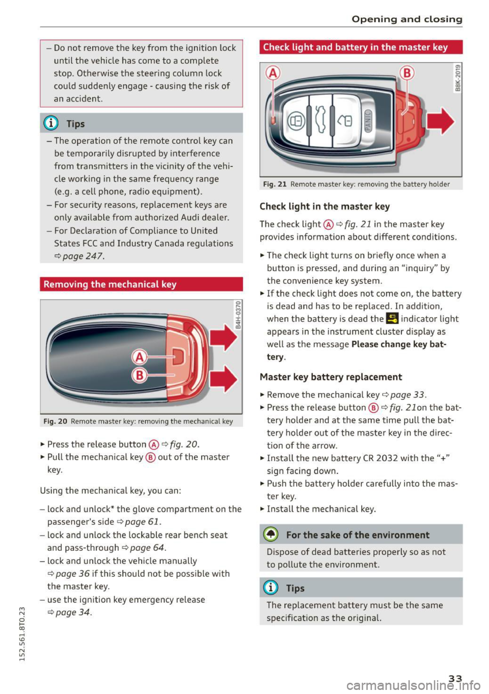
Removing the mechanical key
F ig. 20 Remote maste r key: remov ing the mechanical key
.,. Press the release button @ i:> fig. 20.
.,. Pull the mechan ical key @ out of the master
key .
Using the mechan ical key, you can:
- lock and unlock* the glove compartment on the
passenger's side
i:> page 61 .
-lock and unlock the lockable rear bench seat
and pass-through
c:> page 64 .
-lock and unlock the vehicle manually
i=> page 36 if this should not be possible with
the master key.
- use the ign ition key emergency release
~ i=> page 34.
0 loo
rl I.O
"' N
"' rl
Open ing and clo sing
Check light and battery in the master key
Fig. 2 1 Remote master key: removing th e battery holder
Check light in the master key
The check light @i=> fig. 21 in the master key
provides information about different conditions.
.,. The check light turns on briefly once when a
button is pressed, and during an "inquiry" by
the convenience key system.
.,. If the check light does not come on, the battery
is dead and has to be replaced. In addit ion,
when the battery is dead the
!I i ndicator light
appears in the instrument cluster d isp lay as
well as the message
Pl ea se change k ey bat
tery .
Master key battery replacement
.,. Remove the mechan ical key i=> page 33 .
.,. Press the release button @ c:> fig. 21 on the bat·
tery ho lder and at the same time pull the bat
tery ho lder out of the maste r key in the d irec
tion of the arrow .
.,. Insta ll the new battery CR 2032 with the"+"
sign facing down .
.,. Push the battery holder carefu lly into the mas·
ter key.
.,. Insta ll the mechanical key.
@) For the sake of the env ironment
Dispose of dead batteries properly so as not
to pollute the environment.
@ Tips
The replacement battery must be the same
spec ificat ion as the origina l.
33
Page 37 of 264
M N
0 loo
rl I.O
"' N
"' rl
"'To lock the vehicle, close the door and touch
the sensor in the door hand le
once ¢ fig. 23
¢ A in General description on page 31 . Do not
reach inside the door handle.
The vehicle can be locked and unlocked at any
door. The remote control key cannot be more
than 1.5 m away from the door hand le. It makes
no difference whether the master key is in your
jacket pocket or in your brief case .
If you g rip the door handle while locking, this can
adversely affect the locking function.
It is not possible to re -open the door for a brief
pe riod directly after closing it . This allows yo u to
ensure that the doors are properly locked .
It depends o n the se ttings i n the radio or MM I*
whether the entire vehicle is un locked or one o f
the doors ¢
page 36.
A WARNING
Read and follow all WARNINGS ¢ A in Gener·
al description on page 31.
@ Tips
I f your vehicle has been stand ing fo r an ex
tended period, please note the following:
- The proximity sensors are deac tivated after
a few days to save power. Yo u then have to
pull on the door handle once to unlock the
vehicle and a second time to open the vehi
cle.
- To prevent the battery from being dis
charged and to preserve your veh icle's abili
ty to start for as long as possible, the ener
gy management system g radually switc hes
off unnecessary convenience functions. It is poss ible that you w ill not be ab le to unlock
you r vehicle using these convenie nce func
tions .
- Fo r Decla rat ion of Compliance to Uni ted
Sta tes FCC a nd Industry Canada regulations
~ page 24 7.
Open ing and clo sing
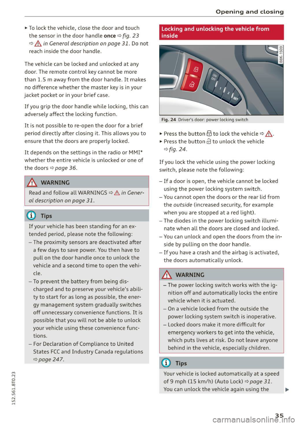
Locking and unlocking the vehicle from
inside
F ig. 2 4 Driver's door; power lock ing sw itch
"' Press the button@ to lock the vehicle¢_& .
"' Press the button@ to unlock the vehicle
¢fig. 24 .
If you lock the veh icle using the power loc king
swit ch, p lease note the following:
- If a door is open, the veh icle cannot be locked
using the power locking system switch .
- You cannot open the doors or the rear lid from
the
outside (increased security, for example
when you are stopped at a red light) .
- The diodes in the power locking switch illumi
nate when a ll the doors are closed and locked .
- You can unlock and open the doors from the in
side by pulling on the door hand le .
- If you have a crash and the airbag is activated,
the doors automa tically unlock .
A WARNING
-- The power lock ing switch works with the ig-
n ition off and automatically locks the entire
veh icle when it is actuated.
- On a vehicle locked from the outside the
power locking sy stem switch is inoperative .
- Locked doors make it more difficult for
emerge ncy worke rs to get into the veh icle,
which puts liv es at r isk. Do not leave anyone
be hind in the vehi cle, especially children .
@ Tips
Your vehicle is locked a utomat ically at a speed
of9 mph ( 15 km/h) (Auto Loc k)
¢ page 31.
You can unlock the veh icle aga in using the .,.
35
Page 39 of 264
M N
0 loo
rl I.O
"' N
"' rl
Once the front passenger's door has been closed,
you cannot open it again from the outside. The
doo r can be opened from the inside by pulling
t he door hand le.
A WARNING
Read and follow all WARNINGS q .&. in Gener
al description on page 31 .
@ Tips
After the ignition is switched on, the power
locking system sw itch and the unlocking but
ton for the rear lid
.c::5 in the door are ena
bled .
Electronic immobilizer
The immobili zer prevents your vehicle from being
s tarted by unauthorized persons .
Inside the key there is a computer chip. This chip
automatically activates/deact ivates the electron
ic immobili zer.
Applie s to vehicl es with ign ition lock :
The electronic immobilizer deactivates automati
cally when you insert the remote control key into
the ignition lock . It activates again automatically
when you remove the remote control key from
t he ignition lock .
Applies to v eh icl es with conven ienc e key :
If t he remote control key is located inside the ve
hicle and you press the
! S TAR T ENGINE ST OPI
button, the electronic immobilizer deactivates
au tomatically . If you switch the igni tion off and
remove the remote control key from the ve hicle,
the electronic immobilizer activates again auto
mat ica lly.
A WARNING
Always take the key with you when you leave
the vehicle. The key ca n disa rm the electron ic
eng ine immob ilizer and permit an unau thor
ized pe rson to start the eng ine and enable op
eration of the vehicle systems such as power
w indow or power sunroof leading to serious
personal in jury.
Open ing and clo sing
(D Tips
- The vehicle cannot be started if an una u
thorized key is used . The vehicle may not
start if another radio device s uch as a key
for another ve hicle or a transponder is locat
ed on the key ring.
- For Declaration of Comp liance to United
States FCC and Industry Canada regulations
¢ page 247.
Luggage compartment
Lid
Opening/closing rear lid
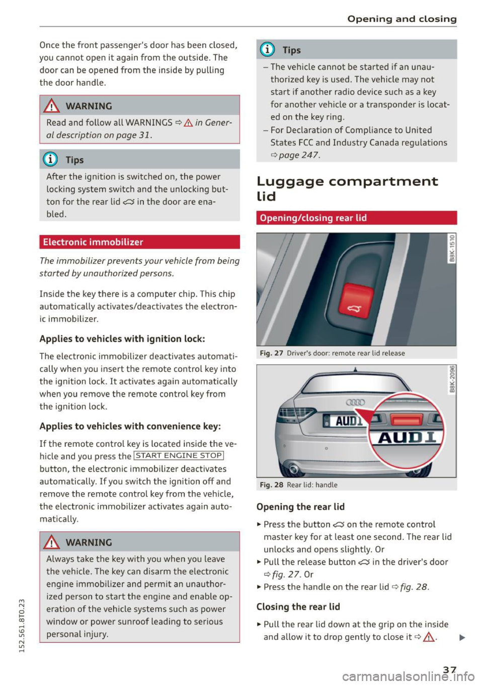
Fig. 2 7 Drive r's doo r: remot e rear lid re le a se
Fig . 2 8 Rea r lid : han d le
Opening the rear lid
.. Press the b utton .c::5 on t he remote control
maste r key for at least o ne second. The rear lid
unlocks and opens slightly. Or
.,. Pull the release button
.c::5 in the driver's door
¢fig. 27. Or
.,. Press the handle on the rear lid¢
fig. 28 .
Closing the rear lid
.. Pull the rea r lid down at the grip on t he i nside
and allow it to drop gent ly to close it¢,&. .
II>-
37
Page 42 of 264
Opening and closing
Panorama roof
Operation
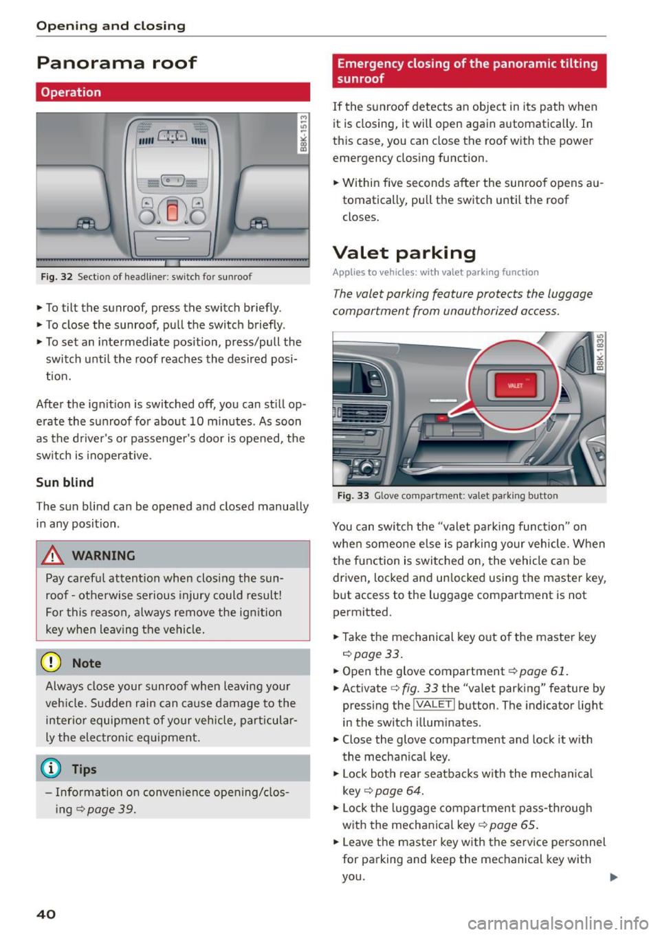
Fig. 32 Sectio n of headliner : swi tc h fo r sunroo f
.,. To tilt the sunroof, press the switch briefly .
• To close the sunroof, pull the switch briefly .
• To set an intermediate position, press/pull the
switch until the roof reaches the desired posi
tion.
After the ignition is switched off, you can still op
erate the sunroof for about 10 minutes . As soon
as the driver's or passenger's door is opened, the
switch is inoperative .
Sun blind
The sun blind can be opened and closed manually in any position .
A WARNING
Pay careful attention when closing the sun
roof - otherwise serious injury could result!
For this reason, always remove the ignition
key when leaving the vehicle.
(D Note
Always close your sunroof when leaving your
veh icle. Sudden rain can cause damage to the
interior equipment of your vehicle, particular
ly the electronic equipment.
- Information on convenience opening/clos
i ng
c::> page 39.
40
Emergency closing of the panoramic tilting
sunroof
If the sunroof detects an object in its path when
it is closing, it will open again automatically . In
this case, you can close the roof with the power
emergency closing function.
• Within five seconds after the sunroof opens au
tomatically, pull the switch until the roof
closes .
Valet parking
Applies to vehicles: wi th valet parkin g function
The valet parking feature protects the luggage
compartment from unau thorized access.
-
Fig. 33 Glove com partment: va let pa rk ing b utto n
You can switch the "valet parking function" on
when someone else is parking your vehicle. When
the function is switched on, the vehicle can be driven, locked and un locked using the master key,
but access to the luggage compartment is not
permitted.
• Take the mechanical key out of the master key
c::>page33.
• Open the glove compartment c::> page 61.
• Activate c::> fig. 33 the "valet parking" feature by
pressing the
! VA LET I button . The indicator light
in the switch illuminates.
• Close the glove compartment and lock it with
the mechanical key .
• Lock both rear seatbacks w ith the mechan ical
key
c::> page 64.
• Lock the luggage compartment pass-through
with the mechanical key
c::> page 65 .
• Leave the master key with the service personnel
for parking and keep the mechanical key with
you.
Page 43 of 264
M N
0 loo
rl I.O
"' N
"' rl
The following buttons are deactivated when the
va let parking function is switched on:
- l'-"' I button in the dr iver's door
- I""' I button on the master key
- Handle in the rear lid
When the valet parking feature is activated, the message
V alet pa rk ing acti vated appears in the
instrument cluster d isp lay when you switch the
ignit ion on .
Garage door opener
(Homelink)
Description
Applies to vehicles: with ga rage door opener (Homeli nk)
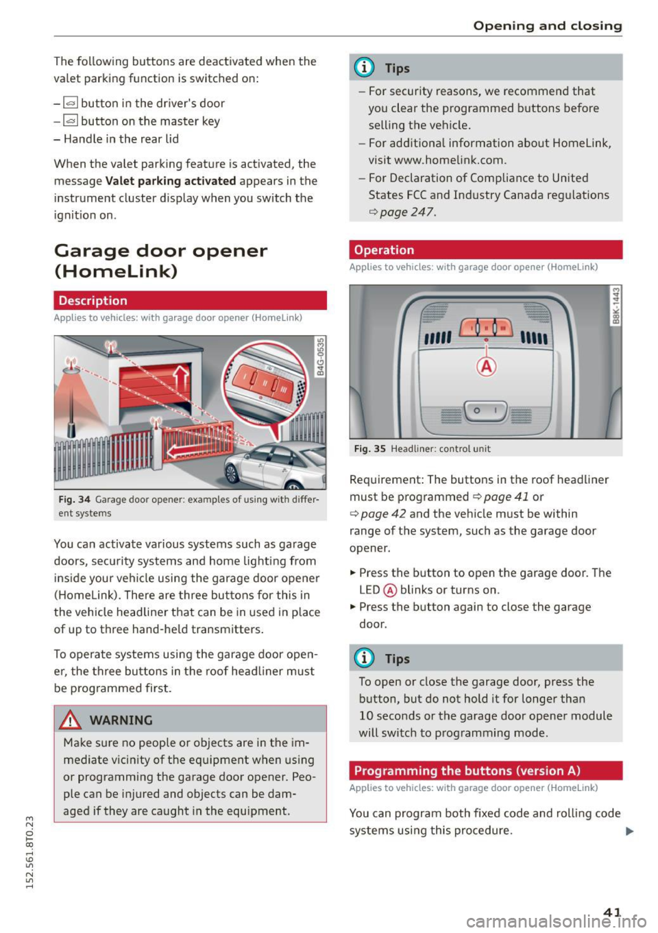
Fig. 34 Garage door opene r: exa mples of us ing wit h differ
ent systems
You can activate various systems such as garage
doors, security systems and home lighting from
i nside your vehicle using the garage door opener
( H omelink). There are three buttons for this in
the vehicle headliner that can be in used in p lace
of up to three hand-he ld transmitters .
To operate systems using the garage door ope n
er, the th ree bu ttons in the roof head liner must
be p rog rammed first.
A WARNING
Make sure no people or objects are in the im
mediate v icin ity of the equipment when us ing
or programming the garage door opener. Peo
ple can be injured and objects can be dam
aged if they are caught in the equipment .
Opening and clo sing
(D Tips
- For security reasons, we recomme nd that
you clear the programmed b uttons before
selling the vehicle.
- For add itiona l information about Homelink
'
visit www.homelink.com.
- For Declaration of Compliance to United
States FCC and Ind ustry Canada reg ulations
¢page 247.
Operation
Applies to vehicles: wit h garage door opener (Homelink)
Fig . 3 5 Headliner : contro l uni t
Requirement: The buttons in the roof headliner
must be programmed ¢
page 41 or
¢
page 42 and the veh icle must be within
range of the system, such as the garage door
opener .
.,. Press the button to open the garage door. The
LED @ blinks or turns on .
.,. Press the button again to close the garage
door .
(D Tips
To open or close the garage door, press the
button, but do not hold it for longer than
10 seconds or the garage door opene r module
will switch to programming mode .
Programming the buttons (version A)
Applies to vehicles: with garage door opener (Homelink)
You can program both fixed code and ro lling code
systems using this procedure. .,.
41
Page 46 of 264
Lights and Vi sion
Lights and Vision
Exterior Lighting
Switching the lights on and off
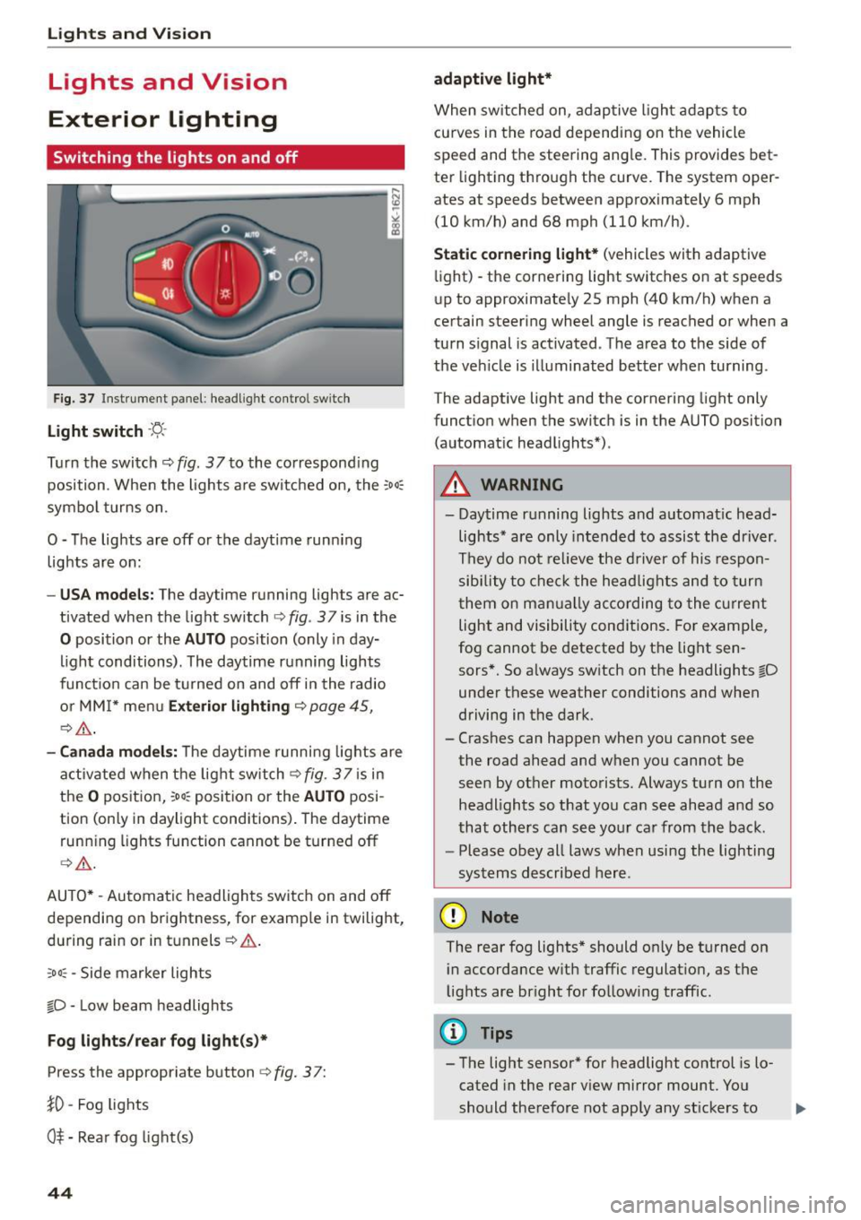
Fig. 3 7 Instrume nt pane l: headl ig h t co ntrol switc h
Light switch ·'t/-·
Tu rn the switch ¢ fig. 37 to the co rr e spond ing
position . Whe n the lights a re switched on, the
:oo,
symbo l turns on.
0 -The lights are off or the daytime runn ing
lights are on:
- USA models : The daytime running lights are ac
tivated when the light sw itch
¢ fig . 37 is in the
0 position or the AUTO position (only in day
li ght conditions). The daytime running lights
funct io n can be turned on and off in the radio
o r MM I* men u
Exterior lighting ¢ page 45,
c:?,& .
-Canada model s: T he daytime r unni ng lights are
activated when the lig ht switch
C?fig. 37 is in
t h e
O pos it ion, 300, position or the AUTO posi
tion (only in daylight conditions) . The daytime
runn ing lights function cannot be turned off
¢ ,A .
AUTO* -Au tomatic headlights swi tch on and off
depending on brightness, for examp le in twilight,
during rain or in tu nnels ¢
A.
:oo , -Side marker lights
fO -Low beam headlights
Fog lights /rear fog light(s )*
Press the appropriate button c:? fig. 3 7:
}0 -Fog lights
O* -Rea r fog light(s)
44
adaptive light*
When switched on, adap tive ligh t ad ap ts to
curves in the road depending on the vehicle
speed and the steering ang le. This provides bet
ter light ing through the curve. The system oper
ates at speeds between approximately 6 mph
(10 km/h) and 68 mph (110 km/h).
Static cornering light* (vehicles with adaptive
li ght) -the corne ring light switches on at speeds
up to approximate ly 25 mph (40 km/h) when a
certain steering wheel angle is reached or when a
turn s ignal is act ivated . T he area to the side of
the ve hicle is illuminated better when turning .
The adaptive light and the cornering light only
funct io n when the switc h is in the AUTO position
(automat ic head lights*) .
A WARNING
- Daytime r unning lights and a utomat ic head
lights* are only intended to as sist the driver .
T h ey do not re lieve the driver of his respon
sibility to c heck t he hea dlights and to tur n
t hem on m anually ac co rding to the cur rent
light and visibili ty conditions. Fo r exam ple,
fog cannot be detected by the light sen
sors*. So a lways sw itch on the headlights
l[D
under these weather conditi ons and when
driving in the dark.
- Crashes can happen when y ou cannot see
the road ahead and when you cannot be
seen by ot her moto rists. Always tu rn on the
headlights so that yo u ca n see ahead a nd so
that othe rs can see yo ur ca r from the back.
- Please obey all laws when usi ng the lighting
sys tems described here.
(D Note
The rear fog lights* should on ly be turned on
i n accordance w ith traffic regulat ion, as t he
lights are br ight for follow ing traffic.
{!) Tips
- The light sensor* for headlight control is lo
cated in the rear v iew mirror mount. Yo u
should the refore not app ly any st ickers to
Page 47 of 264
M N
0 loo
rl I.O
"' N
"' rl
the windshield in this a rea in order to
prevent malfunctions or failures .
- Some exterior lighting functions can be ad
ju ste d
~ page 45 .
-When yo u remove your key from the igni tion
while the vehi cle's ligh ts are turned o n, a
buzzer sounds as long as t he driver 's door is
open.
- In coo l o r dam p weather, t he inside of the
h eadlights, turn sig nals and tail lights can
fog over d ue to the temperature difference
between the inside and outs ide. They will
clea r shortly after switching them on. T his
does not affect t he service li fe of the light
i ng.
- In the event of a light sensor malfunction,
the driver is not ified in the instr ume nt clus
te r display~
page 21.
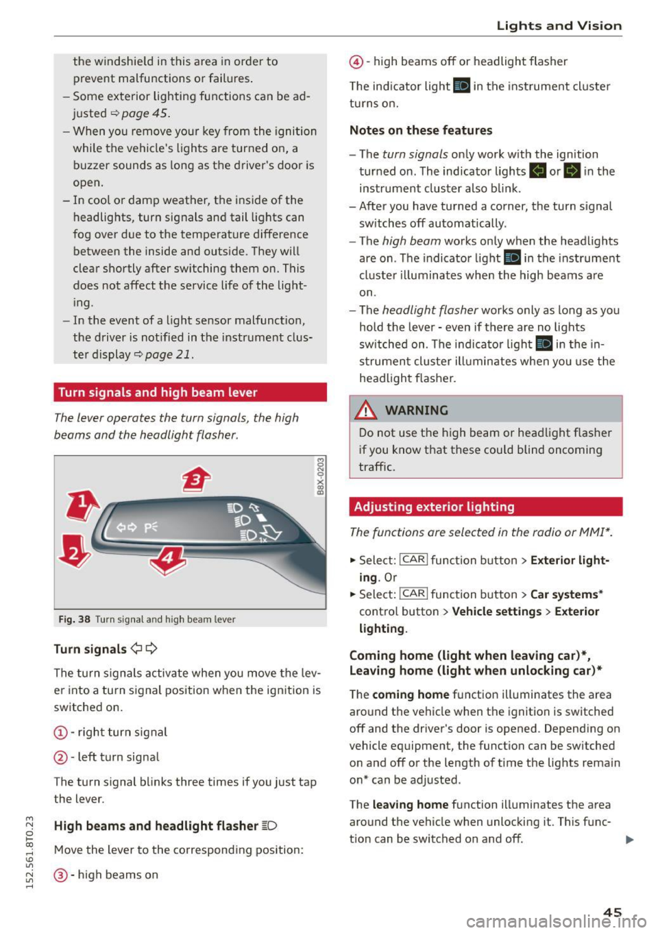
Turn signals and high beam lever
The lever operates the turn signals, the high
b eams and the headlight flasher.
Fi g. 3 8 Tu rn signa l and high beam lever
Turn signals ¢ Q
g N
0
~ CD
The turn signals activate when you move the lev
er into a turn s ignal position when the ignition is
switched on.
@ -righ t tur n signal
@ -left turn signa l
The turn s ignal b links three times if you just tap
the lever.
High beams and headlight flasher
[0
M ove the lever to the corresponding position:
@ -high beams o n
Lights and Vis ion
@ -high beams off or headlight flasher
T he ind icator light
II in t he inst rument cl uste r
tu rns on.
Notes on these features
- The
turn signals on ly wor k w ith the ign ition
tur ned on. The indicator ligh ts . or
II in the
instr um ent clus ter also b link.
-After you have tu rned a corner, the turn s ignal
sw itches off automatically.
- The
high beam works on ly when the headlights
are on . T he indicator light
II in the instrument
cluste r illuminates whe n the high beams a re
on.
- The
headlight flash er works o nly as long as yo u
hold the leve r - even if there are no lights
sw itched on . The indica to r li ght
II in the in
s trumen t cluste r ill umin ates when you use t he
head light flasher.
,&. WARNING
D o not use t he h igh beam or hea dlight flashe r
i f you know that these could blind oncoming
traffic.
Adjusting exterior lighting
The func tions are selected in the radio or MMI* .
.,. Select: !CAR I func tion b utton > Exterior light
ing .
Or
.,. Sele ct: !~C_A _R~ I function b utton > Car systems *
contro l butto n > Vehicle settings > Exterior
lighting .
Coming home (light when leaving car )*,
Leaving home (light when unlocking car)*
The
coming home f u nction illuminates the area
aro und t he vehicle when the ignition is switched
off and the driver's door is opened. Depend ing on
vehicle equipment, the function can be switched o n and off o r the length of t ime t he lig hts rema in
on* can be adjusted .
The
leaving home function illuminates t he area
around th e vehicle when unloc kin g it. This func-
t ion can be switched on and off. ""
45
Page 48 of 264
Lights and Vi sion
The comi ng h ome and leaving h ome fu nctions
only op erat e when it is da rk and the light switch
is in the AUTO position ¢
page 44, fig. 3 7.
Auto headlights*
When the light swit ch is in the A UTO ¢ page 44
posi tion, the sw itch-on po int of the lights can be
changed in the automatic drivi ng light function.
Daytime running lights
USA models :
You can sw itch th e dayt im e running
lights
on and off .
Canada models:
T he function ca nnot be turned
off . It is activated automatically eac h time the ig
n ition is switched on.
Travel mode*
The headlight beam is asymmetrical. This pro
vides stronger illum inat ion on the s ide of the
road on wh ich you a re driving. If you are driving
in a cou ntry that drives o n the opposite side of
the road from your own count ry, this will cause
g lare for oncom ing d rive rs. To prevent glare:
- Travel mode must be selected in vehicles with
Xenon headlights* .
- In veh icles with halogen headlights, certain
areas of the headlight lenses must be covered
with waterproof adhesive cove rs that prevent
l igh t from pass ing t hrough . For more informa
tion, ple ase see you r autho rized Aud i dea le r or
a ut ho rized repair facility.
When tr ave l mode is activa ted, a display in
t he dr ive r inform ati on system i nd ic ates this
e ach t ime yo u sw itch the ignition o n.
46
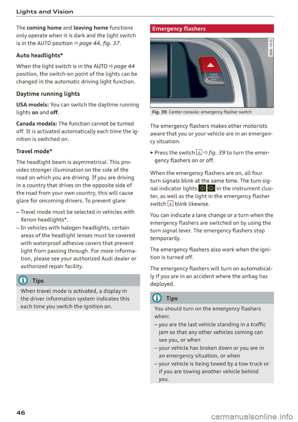
Emergency flashers
Fig. 39 Cente r co nsole : em erg en cy flas he r sw itc h
The emergency flashers makes other motorists
aware that you or you r vehicle a re in an emerge n
cy situat ion .
.. Press the switch~¢
fig. 39 to t urn the emer-
ge ncy flashers on or off.
When the emergency flas hers are on, all fo ur
turn s ignals b link at the same time. The turn sig
nal indicator lights
RB i n the instrument clus
ter, as we ll as the light in the emergency flasher
switch
IA] b link likewise .
You can indicate a lane change or a t urn w hen the
emergency flashers are switched on by using the
turn s ignal leve r. The emergency flashers stop
temporar ily .
The emergency flashers also wo rk when the igni
tion is turned off.
The emergency flashers w ill tu rn on a utomat ica l
l y if you a re in a n accident w here the airbag has
deployed .
@ Tips
You should turn on the emergency f lashers
when:
-yo u are the last veh icle standing in a t raff ic
jam so that any othe r vehicles com ing can
see you, or when
- yo ur vehicle has broken dow n or you a re in
an eme rgency s ituation, or when
-yo ur vehicle is be ing towed by a tow tru ck or
if yo u are towing a not her vehicle behind
you.