95 RON AUDI A8 2018 Owners Manual
[x] Cancel search | Manufacturer: AUDI, Model Year: 2018, Model line: A8, Model: AUDI A8 2018Pages: 356, PDF Size: 54.71 MB
Page 322 of 356
Emergency assistance
There are some restrictions on the use of the
spare tire. The spare tire has been designed spe
cifically for your type of vehicle. Do not replace it
with the spare tire from another type of vehicle.
There are different types of spare tires available
depending on the equipment
c::> page 320.
Removing the spare tire
• Lift the cargo floor by the plast ic ha ndle
c::> fig. 282.
• Hook the hand le into the luggage compartment
weathe r strip.
• Turn the handwheel counter-clockwise and re-
move it.
• Remove the spare tire.
Snow chains
For technical reasons, the use of snow chains on
the compact spare tire is not permitted.
If you have to drive w ith snow chains and a front
tire fails , mount the spare t ire in place of a rear
tire . Install the snow chains on the rear tire that
you removed, and install that in place of the
front tire that failed.
A WARNING
-After installing a spare tire, the tire pres sure must be checked as quickly as possible.
- Do not drive faster than 50 mph (80 km/h)
with a compact spare tire. Driving faster
than that increases the risk of an accident.
- To reduce the risk of an accident, avoid full
throttle acceleration, heavy braking, and
fast cornering with the compact spare t ire.
- To reduce the risk of an accident, never drive
with more than one compact spare tire.
- Norma l summer or winter tires must not be
mounted on the compact spare wheel rim.
A WARNING
- Never use the spare tire if it is damaged or if
it is worn down to the tread wear indicators.
- If the spare tire is more than 6 years old, use it only in an emergency and with ex
treme caution and careful dr iving .
- The spare tire is intended only for tempora
ry and short-term use.
It should be replaced
320
as soon as possible with the normal whee l
and tire.
- For technical reasons, the use of tire chains
on the spare tire is not permitted. If it is
necessary to drive with tire chains, the spare
wheel must be mounted on the front axle in
the event of a flat in a rear tire . The newly
ava ilable front wheel must then be installed
in place of the rear wheel w ith the flat tire.
Installing the tire chain before mounting
the wheel and tire is recommended.
- Loose items in the passenger compartment
can cause serious personal injury during
hard braking or in an accident. Never store
the inflatable spare tire or jack and tools in
the passenger compartment .
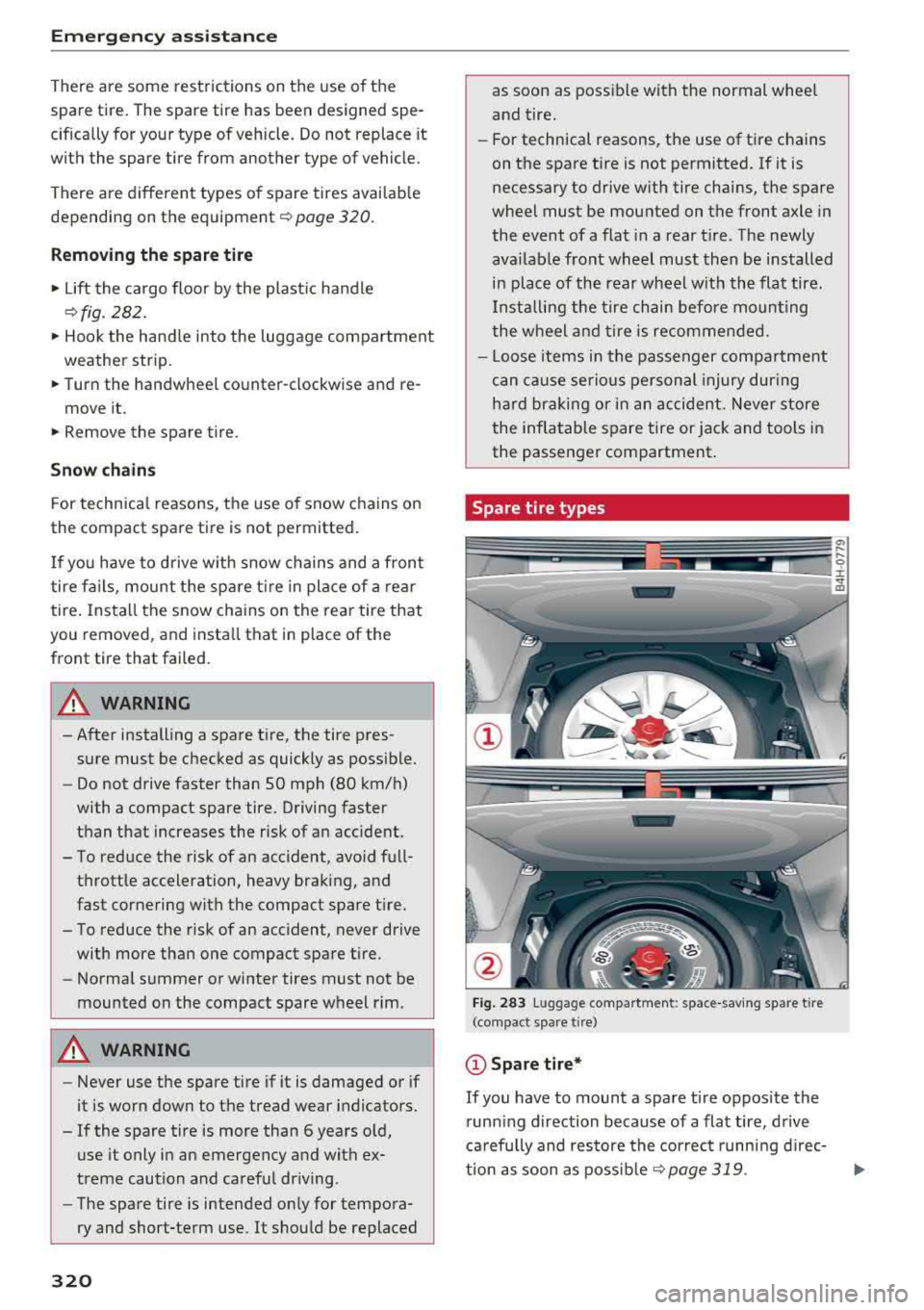
Spare tire types
Fig. 283 Luggage compartment: space -saving spa re t ire
(compact spare tire)
(D Spare tire*
If you have to mount a spare tire oppos ite the
running direction because of a flat tire , drive
ca refully and restore the correc t running direc
tion as soon as possible
<=:>page 319.
Page 324 of 356
Fuses and bulbs
Fuses and bulbs
Electrical fuses
Changing fuses
A fuse that has blown will have metal strips that have burned through .
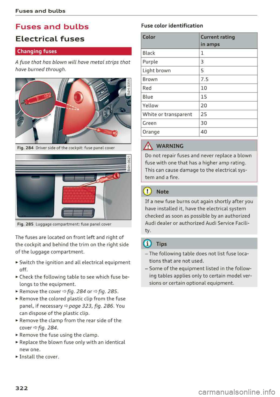
Fig. 284 Driver side of the cockp it: fuse panel cover
1
•
Fig. 285 Luggage compartment: fuse panel cover
The fuses are located on front left and right of
the cockpit and behind the trim on the right side
of the luggage compartment.
.. Switch the ignition and all electrical equipment
off.
.. Check the following table to see which fuse be
longs to the equipment .
.. Remove the cover c::> fig. 284 or c::> fig. 285 .
.. Remove the colored plastic clip from the fuse
panel, if necessary
<=:>page 323 , fig. 286. You
can dispose of the plastic clip .
.. Remove the clamp from the rear side of the
cover
c::> fig. 284 .
.. Remove the fuse using the clamp .
.. Replace the blown fuse only with an identical
new one .
.. Install the cover.
322
Fuse color identification
Color Current rating
in amps
Black 1
Purple 3
Light brown 5
Brown 7.5
Red 10
Blue 15
Yellow 20
White or transparent 25
Green 30
Orange 40
A WARNING
-
Do not repair fuses and never replace a blown
fuse with one that has a higher amp rating.
This can cause damage to the electrical sys
tem and a fire.
(D Note
If a new fuse burns out again shortly after you
have installed it, have the electrical system
checked as soon as possible by an authorized
Audi dealer or authorized Audi Service Fac ili
ty .
(!) Tips
-The following table does not list fuse loca
tions that are not used .
- Some of the equipment listed in the follow
ing tables applies only to certain model ver
sions or certain optional equipment.
Page 325 of 356
lL t:0 ....
'"" ......
'"" .... 0 0 :c '
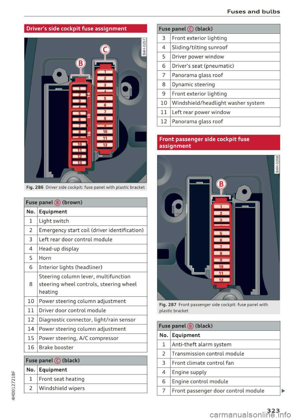
Fig. 286 Drive r side cockpit: fuse panel with plastic bracket
Fuse panel @ (brown)
No. Equipment
1 Light switch
2 Eme rgency start coil (driver iden tification)
3 Left rear door control module
4 Head-up display
5 Horn
6 Interior lights (headliner)
Steering column lever, multifunction
8 steer ing whee l controls, steering wheel
heating
10 Powe r steering column adjustment
11 Driver door control module
12 Diagnostic con nector, light/rain sensor
14 Power steering column adjustment
lS Power steering, A/C compressor
16 Brake booster
Fuse panel © (black)
No. Equipment
1 Front seat heating
2 Windshield wipers
Fuses and bulbs
Fuse panel © (black)
3 Front exterior lighting
4 Sliding/tilting sunroof
5 Driver power window
6 Dr iver 's seat (pne umat ic)
7 Panorama glass roof
8 Dynamic steering
9 Front exterior lighting
10 Windshield/headlight washer system
11 Left rear power window
12 Panorama glass roof
Front passenger side cockpit fuse
assignment
Fig. 287 Fro nt passe nge r side cockp it: fuse panel with
plastic bracket
Fuse panel @ (black)
No. Equipment
1 Anti-theft alarm system
2 Transmission contro l module
3 Front climate control fan
4 Engine s upply
6 Engine control module
7 Front passenger door control module
323
Page 326 of 356
Fuses and bulbs
Fuse panel@ (black ) Fuse panel@ (black)
8 Front passenger power window 11 Right rear power window
9 ESC con trol module 12 Front passenger's seat (pne umatic)
10 E
SC control module
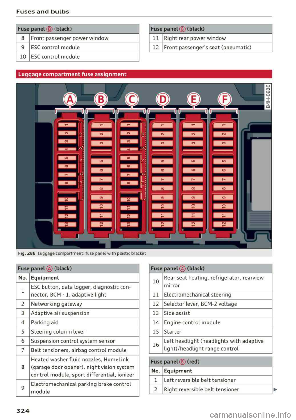
Luggage compartment fuse assignment
F ig . 28 8 Luggage co mpar tment : fuse panel w it h plastic bracket
Fuse panel @ (black) Fuse panel@ (black)
No. Equipment
10 Rear seat heat
ing, refrigerator, rearv iew
1 ESC b
utton , data logger, d iagnost ic con -
nector, BCM - 1, adaptive lig ht mir
ror
1 1 Electromechanical steering
2 Network ing gateway 12 Selec tor lever, BCM-2 vol tage
3 Adaptive air suspension
13 Side assist
4 Park ing a id 14 E ngine contro l module
5 Steer
ing column lever
15 Starter
6 S usp ension contro l system senso r
7 Belt tensioners, airbag control mod ule 16
L
eft head light (he adlights w it h adap tive
li ght)/head light range co ntr ol
Heated w asher flu id no zz les, Home link
8 (garage doo r opener), night vision system
cont rol mod ule, sport differe ntia l, ionizer
9
Electromecha nica l par king brake cont rol
modu le
Fuse panel ® (red)
No . Equipment
1 Left reversible belt tensioner
2 R
ight revers ible belt tensioner
324
Page 327 of 356
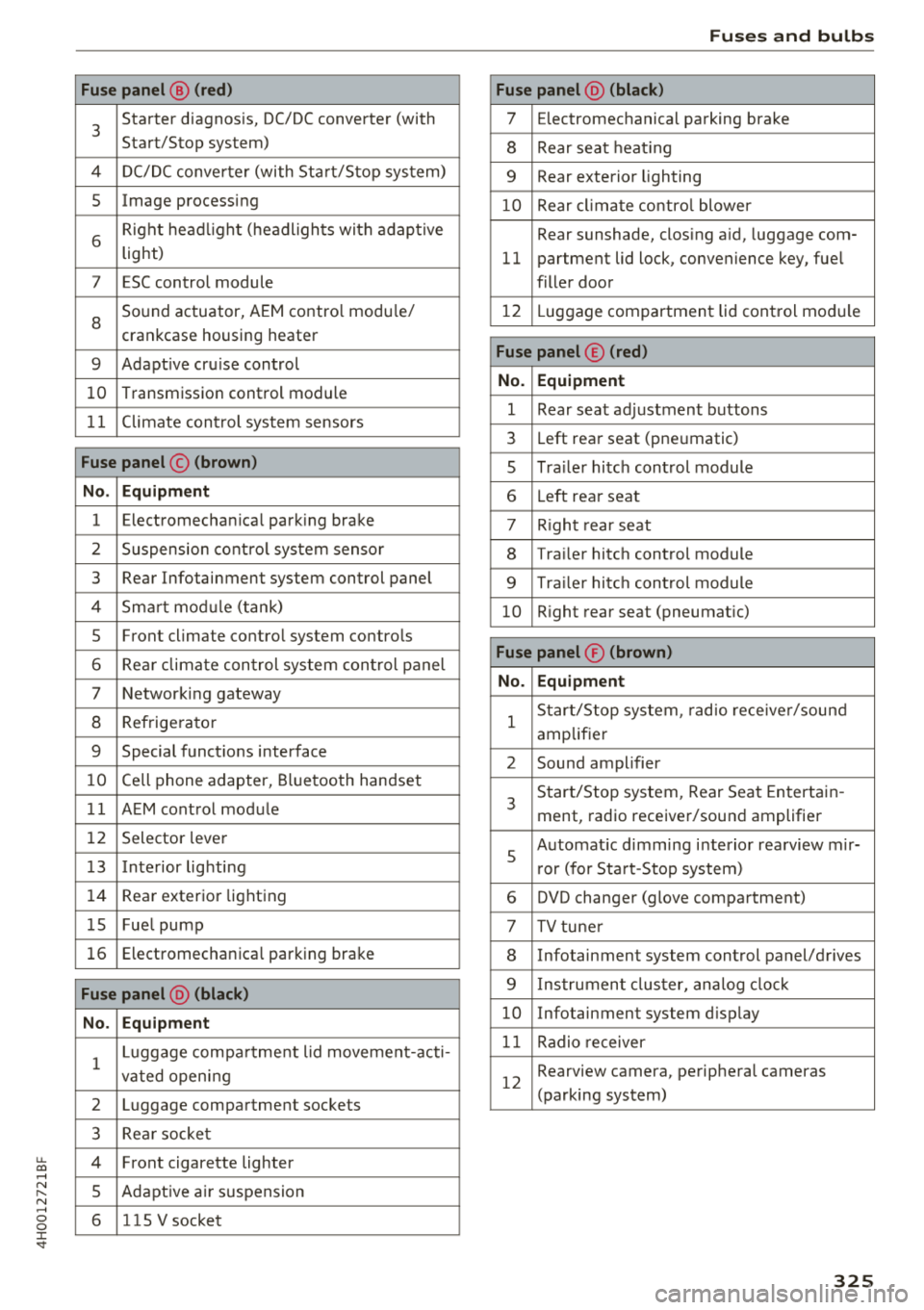
u. co .... N
" N .... 0 0 :c '
3
Starter diagnosis, DC/DC converter (with
Start/Stop system)
4 DC/DC converter (with Start/Stop system)
5 Image processing
6
Right headlight (headlights with adaptive
light)
7 ESC control module
8
Sound actuator, AEM control module/
crankcase housing heater
9 Adapt ive cru ise control
10 Transmission control module
11 Climate control system sensors
Fuse panel © (brown)
No. Equipment
1 Electromechan ica l park ing brake
2 Suspension control system sensor
3 Rear Infotainment system control panel
4 Smart module ( tan k)
5 Front climate control system controls
6 Rea r climate control system control panel
7 Networking gateway
8 Refrigerator
9 Special functions interface
10 Cell phone adapter, Bluetooth handset
11 AEM control module
12 Selector lever
1 3 Inte rior lighting
14 Rear exterior lighting
15 Fue l pump
16 Electromechanica l parking brake
Fuse panel @ (black)
No. Equipment
1
Luggage compa rtment lid movement-acti-
vated opening
2 Luggage compartment sockets
3 Rear socket
4 Fro nt cigarette lighter
5 Adaptive air su spension
6 115 V socket
Fuses and bulbs
Fuse panel @ (black)
7 Electromechanical parking brake
8 Rear seat heat ing
9 Rear exterior lighting
10 Rear climate control blower
Rear sunshade, closing a id, luggage com-
11 partment lid lock, convenience key, fue l
filler door
12 L uggage compartment lid control module
Fuse panel © (red)
No. Equipment
1 Rear seat adjustment buttons
3 Left rear seat (pne umatic)
5 Tra iler hitch control module
6 Left rea r seat
7 Right rear seat
8 Trailer hitch control module
9 Trailer hitch control module
10 Right rear seat (pneumat ic)
Fuse panel ® (brown)
No. Equipment
1
Start/Stop system , radio receiver/sound
amplifier
2 Sound amplifier
3
Start/Stop system, Rear Seat Entertain -
ment, radio receiver/sound amplifier
5
Automat ic dimming interior rea rview mir-
r or (for Start-Stop system)
6 DVD changer (glove compartment)
7 TV tuner
8 Infotainment system control panel/drives
9 Instrument cluster, analog clock
10 Infotainment system d isp lay
11 Radio receiver
12
Rearview camera, perip heral cameras
(parking system)
325
Page 328 of 356
Fuses and bulb s
Bulbs
Replacing light bulbs
For your safety, we recommend that you have
your authorized Audi dealer replace burned out
bulbs for you .
It is becoming increasingly more and more diffi
cult to replace vehicle light bulbs since in many
cases, other parts of the car must first be re moved before you are able to get to the bulb .
This applies espec ially to the light bulbs in the
front of your car wh ich you can only reach
through the engine compartment .
Sheet metal and bulb ho lders can have sharp
edges that can cause ser ious cuts, and parts
must be co rrectly taken apart and then p roperly
put back together to help prevent breakage of
parts and long term damage from water that can
enter housings that have not been properly re
sea led.
F or your safety, we recommend that you have
your authorized Audi dealer replace any bu lbs for
you, since your dealer has the proper tools, the correct bulbs and the expertise.
Ga s di sc ha rge la mp s (Xe non ligh ts):
Due to the high electrical voltage, have the bulbs
replaced by a qua lified techn ic ian . Head lights
with Xenon light can be identified by the high
voltage sticker.
LED headlights* requ ire no maintenance. P lease
contact your authorized Aud i dealer if a bulb
needs to be replaced.
A WARNING
Contact w it h high -vo ltage components of the
electrical system and improper rep lacement
of gas disc harge (Xenon) head light bu lbs can
cause serious personal injury and death.
- Xenon bulbs are pressurized and can ex
plode when being changed.
- Changing Xenon lamps requires the special
training, instructions and equipment.
- Only an a uthorized Audi dea ler or other
qualified workshop s hou ld change the bulbs
in gas disc harge lamps .
326
A WARNING
There are parts with sharp edges on the open
ings and on the bulb holders that can cause
serious cuts .
- If you are uncertain about what to do, have
the work performed by an author ized Audi
dealer or other qual ified workshop . Ser ious
pe rsonal inju ry may resu lt from improperly
pe rformed wor k.
(D Tips
- If you must replace the light bulbs yourself,
always remember that the eng ine compart
ment of any vehicle is a hazardo us a rea to
work in. Always read and heed all WARN INGS
~ page 272.
-It is best to ask you r author ized Audi dea le r
w henever you need to change a bulb.
Page 329 of 356
u. co .... N
" N .... 0 0 :c '
General
This chapter is intended for trained emergency
crews and working personnel who have the nec
essary tools and equipment to perform these
operations.
Starting by pushing or
towing
~ Note
Vehicles with an automatic transmission can
not be started by pushing or towing.
Starting with jumper
cables
If necessary, the engine can be started by con
necting it to the battery of another vehicle .
If the engine should fail to start because of a dis
charged or weak battery, the battery can be con
nected to the battery of
another vehicle, using a
pair of jumper cables to start the engine.
Jumper cables
Use only jumper cables of sufficiently large cross
section
to carry the starter current safely. Refer
to the manufacturer's specifications.
Use only jumper cables with
insulated terminal
clamps which are distinctly marked :
plus(+) cable in most cases colored red
minus(-) cable
in most cases colored black.
A WARNING -
Batteries contain electricity, acid, and gas.
Any of these can cause very serious or fatal in
jury. Follow the instructions below for safe
handling of your vehicle's battery .
-Always shield your eyes and avoid leaning
over the battery whenever possible.
-A dead battery can freeze at temperatures
around 32 °F (0 °C) . If the vehicle battery is
frozen, you must thaw it before connecting
the jump start cables. If you do not, this in-
Emergency situations
creases the risk of an explosion and chemi
cal burns. After jump starting the vehicle,
drive to an authorized Audi dealer or author ized Audi Service Facility immediately to
have the vehicle battery checked.
- Do not allow battery acid to contact eyes or
skin . Flush any contacted area with water
immediately.
- Improper use of a booster battery to start a
vehicle may cause an explosion .
- Vehicle batteries generate explosive gases .
Keep sparks, flame and lighted cigarettes
away from batteries.
- Do not try to jump start any vehicle with a
low acid level in the battery .
- The voltage of the booster battery must also
have a 12-Volt rating . The capacity (Ah) of
the booster battery should not be lower
than that of the discharged battery. Use of
batteries of different voltage or substantial
ly different "Ah " rating may cause an explo
sion and personal injury.
- Never charge a frozen battery. Gas trapped
in the ice may cause an explosion.
- Never charge or use a battery that has been
frozen. The battery case may have be weak
ened.
- Use of batteries of different voltage or sub
stantially different capacity (Ah) rating may
cause an explosion and injury. The capacity
(Ah) of the booster battery should not be
lower than that of the discharged battery.
- Before you check anything in the engine
compartment, always read and heed all
WARNINGS
c>page 272.
@ Note
- Applying a higher voltage booster battery
will cause expensive damage to sensitive
electronic components, such as control
units, relays, radio, etc.
- There must be no electrical contact between
the vehicles as otherwise current could al
ready start to flow as soon as the positive
( + ) terminals are connected.
327
Page 331 of 356
-When connecting jumper cables, make sure
that they cannot get ca ught in any mov ing
parts in the engine compartment.
- Before you check anything in the engine
compartment, a lways read and heed a ll
WARNINGS
¢ page 272.
(D Note
Impro per hook-u p of jum per cables can ru in
the generato r.
- Always connect P OSITIVE( +) to POSITIV E
( + ), and NEGATIVE( -) to NEGATIVE( -)
g round post of the battery manager contro l
unit.
- Check that a ll sc rew p lugs on the battery
cells are sc rewed in firmly . If not, t ighten
pl ugs p rior to connect ing clamp on negative
b atte ry te rmi nal.
- Please note t hat the procedure fo r con nect
i ng a jumper cab le as desc ribed above ap
p lie s specifica lly to the case of yo ur vehicle
b eing ju mp starte d. When you are g iv ing a
ju mp s tart to ano ther vehicle, do
not con
n ect th e neg ative( -) ca b le to the neg ative
(-) t ermin al on t he disch arged batte ry @
¢ fig . 290. Instead, securely connect the
negat ive(- ) cab le to either a solid metal
component that is f irm ly bolted to the en
gine block o r to the engine bloc k itself. If
the battery that is be ing c ha rged does not
vent to the outs ide, escap ing batte ry gas
could ignite and ex plod e!
Towing with a tow truck
General hints
Yo ur Audi requires special h andling for towing .
The follow ing informa tion is to be used by com
mercia l tow tr uck o pera tors who know how to op
e rat e the ir equip men t sa fely.
- Never tow your Audi. Towing will cause dam
age to the engine and transmission.
- Never wrap the safety chains or winch cables
~ around the brake lines. ....
~ -To prevent unnecessary damage, your Audi N
8 must be transported with a flatbed truck. 0 :c '
-To load the vehicle on to the flatbed, use the
towing loop found in the vehicle tools and at
tach to the front or rear anchorage
¢ page 329 and c> page 330.
A WARNING
A veh icle being towed is not safe for passen
ge rs. Neve r allow a nyo ne to ride in a vehicl e
b eing towed, fo r any reason.
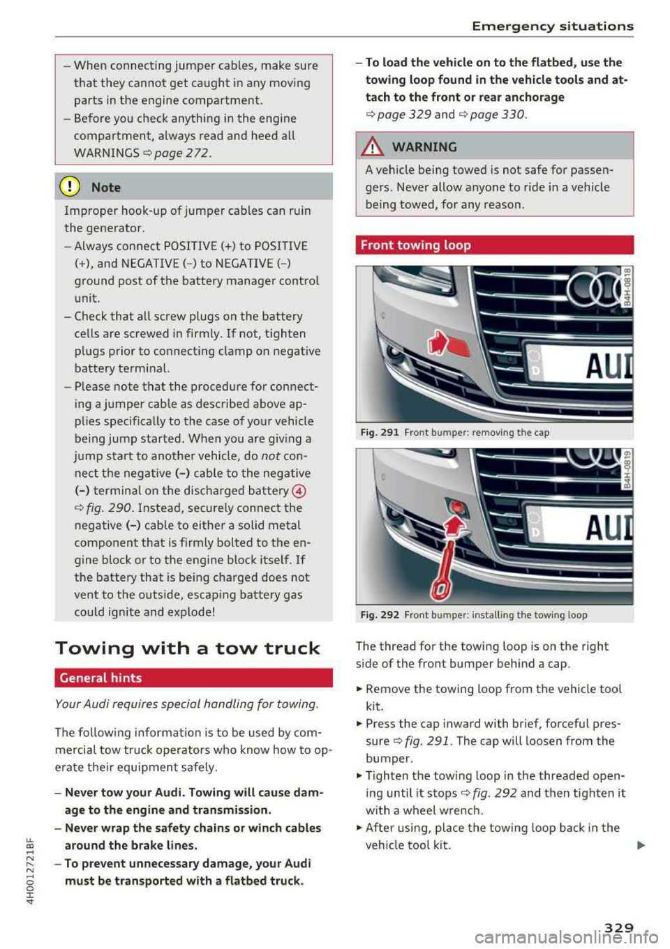
Front towing loop
Fi g. 291 Fron t bu mpe r: removing t he cap
Fig. 292 Fron t bu mpe r: insta llin g the tow ing loop
The thread for the towing loop is on the right
s ide of the front bumper beh ind a cap.
.,. Remove the towing loo p from the vehicle too l
kit.
.,. Press the cap inward with brief, forceful pres
sure
c> fig. 291 . The cap will loosen from the
bumper.
.,. T igh ten the tow ing loop in the threaded open
ing until it stops
c> fig. 292 and t hen tighten it
w ith a wheel w re nc h .
.,. Afte r usi ng, p lace the tow ing loop b ack in the
veh icle tool kit.
IJJ>-
329
Page 332 of 356
Emergency situations
& WARNING
If the towing loop is not tightened until it
stops when installing, the threads may be
pulled out when towing the vehicle and that
could cause an accident.
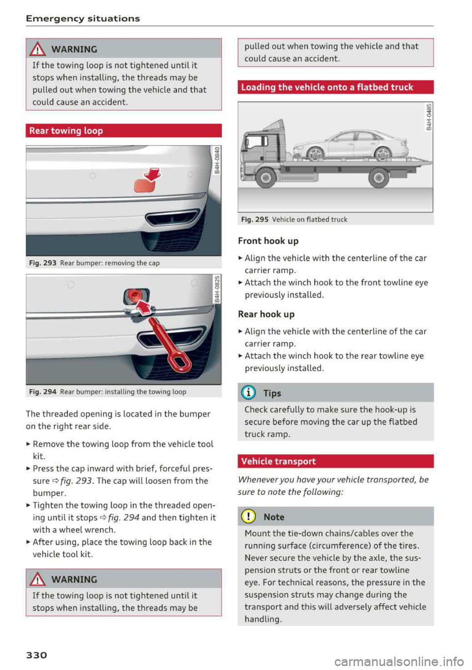
Rear towing loop
Fig. 293 Rear bumper: re moving the cap
Fig. 294 Rear bumper : installi ng the towing loop
The threaded opening is located in the bumper
on the right rear side .
• Remove the towing loop from the vehicle tool
kit .
• Press the cap inward with brief, forceful pres
sure ¢
fig. 293 . The cap will loosen from the
bumper .
• Tighten the towing loop in the threaded open
ing until it
stops¢ fig. 294 and then tighten it
with a whee l wrench .
• After using, place the towing loop back in the
vehicle tool kit.
A WARNING
If the towing loop is not tightened until it
stops when installing, the threads may be
330
-
pulled out when towing the vehicle and that
could cause an accident .
Loading the vehicle onto a flatbed truck
Fig. 295 Vehicle on f latbed tru ck
Front hook up
• Align the vehicle with the centerline of the car
carrier ramp.
• Attach the winch hook to the front towline eye
previously installed.
Rear hook up
• Align the vehicle wi th the centerl ine of the car
carrier ramp.
• Attach the w inch hook to the rear towline eye
previously installed.
@ Tips
Check carefully to make sure the hook-up is
secure before moving the car up the flatbed
truck ramp.
Vehicle transport
Whenever you hove your vehicle transported, be
sure to note the following:
(D Note
Mount the tie-down chains/cables over the
running surface (ci rcumference) o f the tires.
Never secure the vehicle by the axle, the sus
pension struts or the front or rear towline
eye. For technical reasons, the pressure in the
suspension struts may change during the
transport and this will adversely affect vehicle handling.
Page 333 of 356
lL t:0 ....
"' ......
"' .... 0 0 :c '
Lifting with workshop hoist and with floor
jack
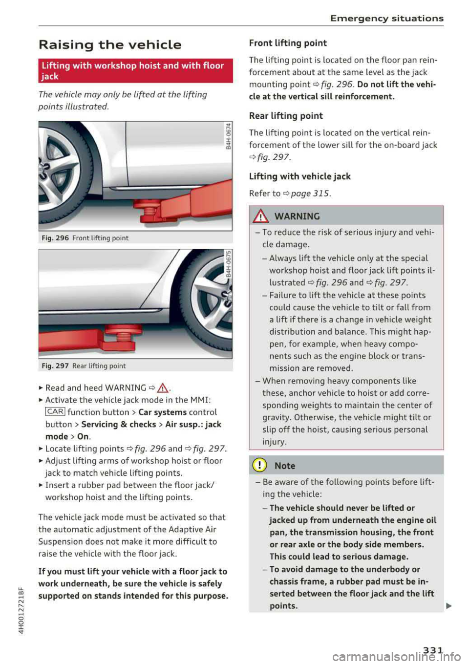
The vehicle may only be lift ed at the lifting
points illus tr at ed.
Fig. 296 Fro nt lift in g poin t
Fig. 29 7 Rear lift ing poin t
.,. Read and heed WARNING c::> &, .
.. Activate the veh icle ja ck mode in the MMI :
I CARI funct ion button> Car systems control
button >
Servicing & checks > Air susp.: jack
mode > On .
.. Loca te lift ing po ints c::> fig . 296 and c::>fig . 297 .
.. Adju st lifting arms of wo rkshop ho ist o r floo r
ja ck t o ma tch vehicle li fting poin ts.
.. In se rt a rubb er pa d between the floor j ack/
wor kshop ho ist and the lifting points .
T he vehicle ja ck mode m ust be a ct iv a te d so th at
the au tomatic a djustment of the Ad aptive Air
Suspension does not m ake it more diffic ult to
raise the ve hicle wit h the floor jack.
If you must lift your vehicle with a floor jack to
work underneath , be sure the vehicle is safely
supported on stands intended for this purpose .
Emergency situations
Front lifting point
The lifting poi nt is locate d on the floor p an rein
f o rcement about at the same level as the ja ck
mounting point
c::> fig . 296 . Do not lift the vehi
cle at the vertical sill reinforcement .
Rear lifting point
T he lifting p oin t i s lo cate d on the ve rtic al rei n
f o rceme nt o f th e lower s ill for the on- bo ar d jac k
c::>fig. 297 .
Lifting with vehicle jack
Refer to c::> pag e 315 .
A WARNING
- To reduce the r is k of se rious inju ry and veh i
cle dama ge.
- Always lift the vehicle o nly at the specia l
wor kshop h oist a nd f loor jack lift points
il
l ustrated c::> fig. 296 and c::> fig. 297.
- Failure to lift t he ve hicle at these points
could cause the veh icle to tilt o r fall from
a lift i f there is a change in vehicle weight
dist ribution and balance . This might hap
pen, fo r example, when h eavy compo
nents such as the eng ine block o r trans
missi on are re moved .
- Whe n re mov ing heavy comp onents like
these, an ch or veh icle t o hois t or ad d co rre
spon ding weig hts t o m aintai n the cen ter of
g ravi ty . Ot herw ise, the vehicle mig ht tilt or
slip off t he hoist, caus ing se rio us pe rsonal
i njur y .
(D Note
- Be aw are of the fo llow ing po ints b efor e lift
ing the vehicle:
-The vehicle should never be lifted or
jacked up from underneath the engine oil
pan, the transmission housing, the front
or rear axle or the body side members.
This could lead to serious damage .
- To avoid damage to the underbody or
chassis frame, a rubber pad must be in
serted between the floor jack and the lift
points .
.,.
331