AUDI E-TRON 2020 Owners Manual
Manufacturer: AUDI, Model Year: 2020, Model line: E-TRON, Model: AUDI E-TRON 2020Pages: 316, PDF Size: 85.96 MB
Page 281 of 316

4KE012721BE
Emergency assistance
Removing and installing a wheel
@ Rg Tt
“ 0 oO
B8K-1477
Fig. 175 Wheel: alignment pin in the top hole
Removing a wheel
> Remove the top wheel bolt completely using
the hex socket in the screwdriver handle from
the vehicle tool kit > fig. 174 and place it ona
clean surface.
> Then install the alignment pin from the vehicle
tool kit in the empty wheel bolt hole by hand
> fig. 175.
> Remove the rest of the wheel bolts.
> Remove the wheel >). The alignment pin re-
mains in the hole while doing this.
Installing a wheel
Read the directions on > page 279 when instal-
ling unidirectional tires.
> Slide the wheel on over the alignment pin >@.
> Install the wheel bolts and tighten them gently
using the hex socket.
> Remove the alignment pin and tighten the re-
maining wheel bolt.
> Carefully lower the vehicle using the vehicle
jack*.
> Tighten the wheel bolts in a diagonal pattern
using the wheel wrench*.
The wheel bolts must be clean and loosen and
tighten easily. Check the contact surfaces for the
wheel and hub. Contaminants on these surfaces
must be removed before installing the wheel.
ZA\ WARNING
— Read and follow the important information
and notes under > page 255.
— Never use the hex socket in the screwdriver
handle to tighten the wheel bolts. Using the
hex socket will not achieve the required
tightening torque, which increases the risk
of an accident.
() Note
When removing or installing the wheel, the
rim could hit the brake rotor and damage the
rotor. Work carefully and have a second per-
son help you.
Unidirectional tires
A unidirectional tire profile is identified by arrows
on the tire sidewall that point in the running di-
rection. You must always maintain the specified
running direction. This is necessary to ensure the
tire's optimal performance in regard to adhesion,
running noise, and friction, and to reduce the risk
of
hydroplaning.
To benefit fully from the advantages of the uni-
directional tire design, you should replace faulty
tires as soon as possible and restore the correct
running direction on all of the tires.
> Reinstall the caps on the wheel bolts if necessa-
ry.
> Store the vehicle tool kit in its designated
place.
> If the removed wheel does not fit in the spare
wheel well, store it securely in the luggage
compartment > page 77.
> Check the tire pressure on the installed wheel
as soon as possible.
> Correct the tire pressure and store it in the MMI
=> page 267. >
279
Page 282 of 316

Emergency assistance
> The wheel bolt tightening specification must be
120 ft lbs (160 Nm). Have it checked as soon as
possible with a torque wrench. Drive carefully
until then.
> Have the faulty wheel replaced as quickly as
possible.
Collapsible spare tire
Applies to: vehicles with collapsible spare tire
The collapsible spare tire is intended for short-
term use only. Have the damaged tire checked
and replaced if necessary by an authorized Audi
dealer or authorized Audi Service Facility as soon
as possible.
There are some restrictions on the use of the col-
lapsible spare tire. The collapsible spare tire has
been designed specifically for your type of vehi-
cle. Do not replace it with the collapsible spare
tire from another type of vehicle.
The collapsible spare tire is located in the lug-
gage compartment under the cargo floor cover.
Requirement: the vehicle tool kit > page 274 and
the compressor must be laid out.
Removing
> Lift the cargo floor using the handle.
> Turn the handwheel counter-clockwise and re-
move it.
> Remove the cover.
> Remove the collapsible spare tire.
You must inflate the collapsible spare tire before-
hand in order to use it.
Inflating
> Remove the valve cap from the collapsible
spare tire.
> Tighten the compressor hose on the collapsible
spare tire valve.
> Connect the compressor hose to a vehicle sock-
et and switch it on.
> Let the compressor run until the specified value
on the tire pressure sticker is reached
> page 258, fig. 164>©,.
> Screw the valve cap back onto the valve.
280
Returning to storage
> To release air, turn the valve insert. See an au-
thorized Audi dealer or authorized Audi Service
Facility.
> Turn the valve insert back once the air has been
released.
>» Wait several hours before placing the collapsi-
ble spare tire in the spare wheel well. Only then
will it fold down completely so that you can
store it securely.
> Then screw the valve cap back onto the valve.
> Secure the collapsible spare tire with the cover
and the handwheel.
> Fold the cargo floor cover back into place.
Snow chains
Using snow chains on the collapsible spare tire is
not permitted for technical reasons.
If you have to drive with snow chains and a rear
tire fails, mount the collapsible spare tire in place
of a front tire. Install the snow chains on the
front tire that you removed, and install that in
place of the rear tire that failed.
Z\ WARNING
— Only use the collapsible spare tire in emer-
gencies and drive very carefully, especially if
it is more than six years old.
— The compressor and the hose can become
very hot during operation which increases
the risk of burn injuries.
— After installing a collapsible spare tire, the
tire pressure must be checked as quickly as
possible to reduce the risk of an accident.
— Do not drive faster than 50 mph (80 km/h)
with the collapsible spare tire. Driving faster
than that increases the risk of an accident.
— To reduce the risk of an accident, avoid hard
acceleration or braking and driving fast
around curves with the collapsible spare
tire.
— Never drive using more than one collapsible
spare tire, because this increases the risk of
an accident.
— Normal tires or winter tires must not be
mounted on the collapsible spare tire rim.
Page 283 of 316

4KE012721BE
Emergency assistance
@) Note
The compressor must be switched off after six
minutes at the most to reduce the risk of
overheating. Let the compressor cool down
for several minutes before using it again.
G) Tips
The ESC must not be limited or switched off
when driving with the collapsible spare tire
=>page 105.
Jump starting
The vehicle cannot be operated when the 12 Volt
vehicle battery is drained. Your vehicle must not
be jump started in this case. Contact an author-
ized Audi dealer or authorized Audi Service Facili-
ty.
@) Note
The vehicle battery must not be bridged using
conventional jump start methods.
— You may neither give nor receive a jump
start. Otherwise, the electronic systems in
the vehicle may be severely damaged.
— The jump start pins in the motor compart-
ment are designed specifically for qualified
technicians.
Towing
General information
You should only perform the steps that follow if
you have the necessary tools and technical ex-
pertise.
Towing requires a certain amount of practice.
Audi recommends contacting a towing company
to have the vehicle transported.
You should only have your vehicle towed by an-
other vehicle when disabled in exceptional cir-
cumstances. Inexperienced drivers should not
tow.
Notes on towing
— The maximum permitted towing speed is 30
mph (50 km/h).
— The maximum permitted towing distance is 30
miles (50 km).
Additional information on towing with a tow
truck
The vehicle may only be towed with the front axle
raised. Do not wrap any chains or cables around
the brake lines.
Tow bar and towing cable
The vehicle can be towed with a tow bar or tow-
ing cable. Both drivers should be familiar with
the special considerations when towing, especial-
ly when using a towing cable.
Always make sure the traction force does not ex-
ceed the permitted level and there are no shock
loading conditions. There is always the risk of the
coupling becoming overloaded when driving off-
road.
For the most safety and security, drive with a tow
bar. You should use a towing cable only if a tow
bar is not available. Use a towing cable made of
synthetic elastic cable similar elastic material.
Z\ WARNING
— Towing highly increases the risk of an acci-
dent, for example from colliding with the
towing vehicle.
—To reduce the risk of an accident, do not al-
low anyone to remain inside the vehicle
when it is being transported by a tow truck
or a special transporter.
® Note
—Ifthe /E| indicator light turns on, there is a
fault in the cooling circuit. The vehicle must
not be towed. The drive system can be se-
verely damaged.
— If normal towing is not possible, for exam-
ple if the transmission is faulty or if the
towing distance is greater than 30 miles
(50 km), then transport the vehicle on a
special carrier.
— If the vehicle is towed by a tow truck at the
axle that is not permitted, this can cause se-
vere damage to the transmission.
281
>
Page 284 of 316

Emergency assistance
— When the parking lock is engaged, neither
the front nor rear axle may be lowered or
raised more than 10. The driveshafts or
tires could be seriously damaged.
— Towing must not be used to charge the
high-voltage battery (recuperation), be-
cause this could result in major damages to
the tow vehicle or the vehicle being towed.
— The vehicle must not be tow started for
technical reasons.
@ Tips
— Switch Audi pre sense* off > page 158 when
loading the vehicle onto a vehicle carrier,
train, ship, or other type of transportation,
or when towing the vehicle. This can prevent
an undesired intervention from the pre
sense* system.
— Follow the local legal regulations for tow-
ing.
Read and follow the important information under
=> page 281.
Preparations
> Only secure the towing cable or tow bar at the
designated towing loops > page 282,
> page 283.
> Make sure the towing cable is not twisted. Oth-
erwise it could disconnect from the towing loop
while towing.
> Switch the emergency flashers on in both
vehicles > page 47. However, do not do this if it
prohibited by law.
Towing vehicle (front)
> Only start to drive when the towing cable is
taut.
> Press the brake pedal very carefully.
> Avoid sudden braking or driving maneuvers.
Vehicle being towed (rear)
> Make sure the ignition is switched on so that
the steering wheel is not locked and so that you
can use the turn signals, the horn, and the
windshield wipers if needed > A\.
282
> Switching it off before the vehicle has stopped
may impair the function of the brake booster
and power steering. You would then need to
use more force to steer and brake the vehicle.
> Release the parking brake > page 96.
> Select the “N” selector lever position.
> Switch the ESC off to avoid error messages
=> page 105.
> Make sure the towing cable is always taut.
ZA WARNING
— Never tow a vehicle using a tow bar or tow-
ing cable if the vehicle does not have electri-
cal power.
— If the vehicle runs out of power while it is
being towed, stop towing the vehicle imme-
diately and consult an authorized Audi deal-
er or qualified repair facility.
Front towing loop
Fig. 176 Front bumper: installing the towing loop
The threaded opening for the towing loop is lo-
cated on the right side of the front bumper.
» Remove the towing loop from the vehicle tool
kit > page 274.
> Press the cap inward with brief, strong pressure
=> fig. 176. The cap will loosen from the bump-
er.
> Tighten the towing eye as far as it will go into
the mount. Use a suitable object to tighten the
towing eye completely and securely in the
mount.
> After using, place the towing loop back in the
vehicle tool kit.
Page 285 of 316

4KEO12721BE
Emergency assistance
If the towing loop is not tightened until it
stops when installing, the threads may be
pulled out when towing the vehicle and result
in an accident.
If the towing loop is not tightened until it
stops when installing, the threads may be
pulled out when towing the vehicle and result
in an accident.
Depending on the model, the shape of the cap
can vary.
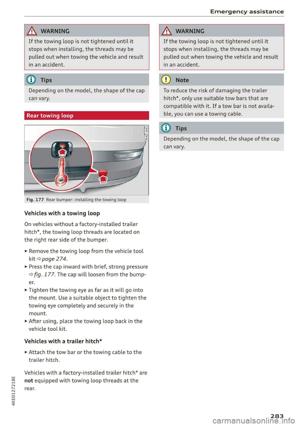
Fig. 177 Rear bumper: installing the towing loop
Vehicles with a towing loop
On vehicles without a factory-installed trailer
hitch*, the towing loop threads are located on
the right rear side of the bumper.
> Remove the towing loop from the vehicle tool
kit > page 274.
>» Press the cap inward with brief, strong pressure
> fig. 177. The cap will loosen from the bump-
er.
> Tighten the towing eye as far as it will go into
the mount. Use a suitable object to tighten the
towing eye completely and securely in the
mount.
> After using, place the towing loop back in the
vehicle tool kit.
Vehicles with a trailer hitch*
>» Attach the tow bar or the towing cable to the
trailer hitch.
Vehicles with a factory-installed trailer hitch* are
not equipped with towing loop threads at the
rear.
To reduce the risk of damaging the trailer
hitch*, only use suitable tow bars that are
compatible with it. If a tow bar is not availa-
ble, you can use a towing cable.
Depending on the model, the shape of the cap
can vary.
283
Page 286 of 316

Fuses and bulbs
Fuses and bulbs
Fuses
oer mie
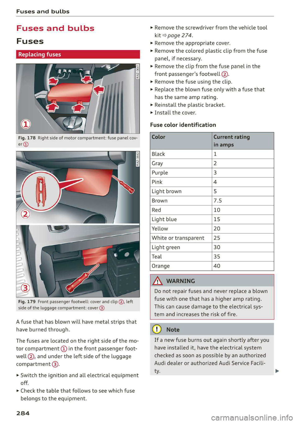
Fig. 178 Right side of motor compartment: fuse panel cov-
Fig. 179 Front passenger footwell: cover and clip @, left
side of the luggage compartment: cover 3)
A fuse that has blown will have metal strips that
have burned through.
The fuses are located on the right side of the mo-
tor compartment (@) in the front passenger foot-
well (2), and under the left side of the luggage
compartment @).
> Switch the ignition and all electrical equipment
off.
> Check the table that follows to see which fuse
belongs to the equipment.
284
» Remove the screwdriver from the vehicle tool
kit > page 274.
>» Remove the appropriate cover.
> Remove the colored plastic clip from the fuse
panel, if necessary.
> Remove the clip from the fuse panel in the
front passenger’s footwell @).
> Remove the fuse using the clip.
> Replace the blown fuse only with a fuse that
has the same amp rating.
> Reinstall the plastic bracket.
> Install the cover.
Fuse color identification
Color Current rating
in amps
Black 1
Gray 2
Purple 3
Pink 4
Light brown 5
Brown 7.5
Red 10
Light blue 15
Yellow 20
White or transparent [25
Light green 30
Teal 35
Orange 40
ZA WARNING
Do not repair fuses and never replace a blown
fuse with one that has a higher amp rating.
This can cause damage to the electrical sys-
tem and increases the risk of fire.
@) Note
If a new fuse burns out again shortly after you
have installed it, have the electrical system
checked as soon as possible by an authorized
Audi dealer or authorized Audi Service Facili-
ty.
Page 287 of 316

4KE012721BE
Fuses and bulbs
@ Tips
— The following table does not list fuse loca-
tions that are not used.
— Some of the equipment listed in the follow-
ing tables applies only to certain model ver-
sions or certain optional equipment.
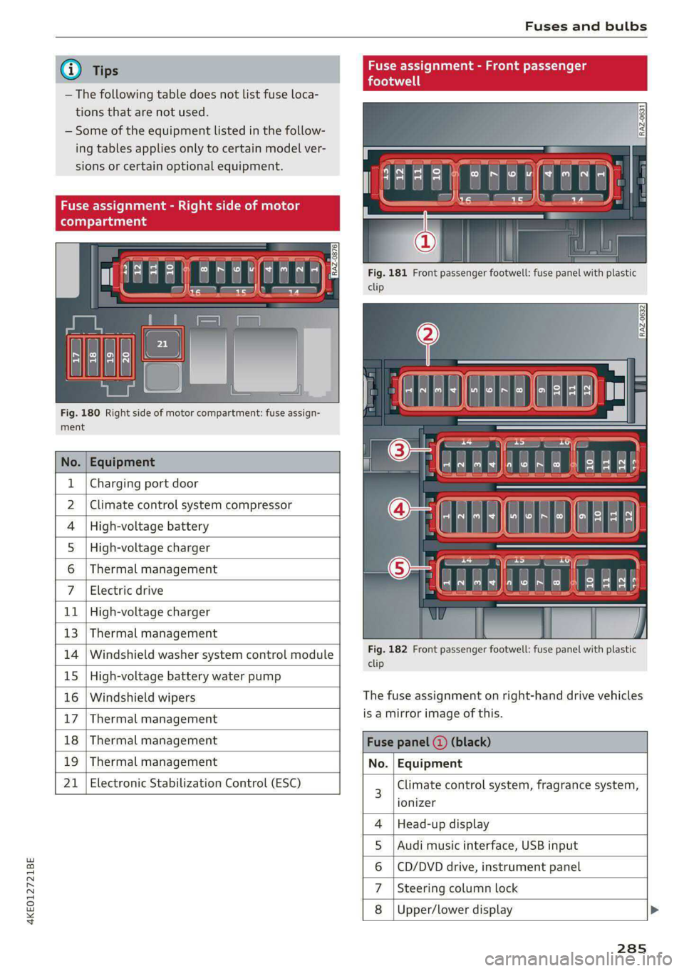
Fig. 180 Right side of motor compartment: fuse assign-
ment
| 33 a |
<| ce|
No. | Equipment
Charging port door
Climate control system compressor
High-voltage charger
Thermal management
1
2
4 |High-voltage battery
5
6
7 Electric drive
11 | High-voltage charger
13 | Thermal management
14 | Windshield washer system control module
15 | High-voltage battery water pump
16 | Windshield wipers
17 | Thermal management
nment - Front |
Fig. 181 Front passenger footwell: fuse panel with plastic
clip
Fig. 182 Front passenger footwell: fuse panel with plastic
clip
The fuse assignment on right-hand drive vehicles
is a mirror image of this.
18 | Thermal management Fuse panel
19 | Thermal management No. | Equipment
21 | Electronic Stabilization Control (ESC) 3 Climate control system, fragrance system,
lonizer
4 |Head-up display
5 |Audi music interface, USB input
6 |CD/DVD drive, instrument panel
7 |Steering column lock
8 |Upper/lower display
285
Page 288 of 316

Fuses and bulbs
Fuse panel (a) (black) Fuse panel (4) (brown)
9 |Instrument cluster No. | Equipment
10 | Volume control 2 | Right front safety belt tensioner
11 | Light switch, switch panels 4 |Left front safety belt tensioner
12 | Steering column electronics 5 |Air suspension/suspension control
15 | Steering column adjustment 6 |Right headlight
16 | Steering wheel heating 7 |Left headlight
Fuse panel @) (black) 8 Left rear door control module
No. Equipment 9 |Right rear door control module
1 |Front seat heating 10 | Infotainment system control module
2 |Cimatecantral system 11 | Driver assistance systems control module
3 | Left headlight electronics 12 | Diagnostic intentawe
4 |Panoramic glass roof Fuse panel (5) (black)
5 |Left front door control module No. | Equipment
6 | Sockets 1 Seat electronics, front seat ventilation,
8 | Instrument panel rearview mirror, diagnostic connection
9 | Right headlight electronics 2 Vehicle electrical system control module,
Windshield washer system/headlight diagnostic interface
10 washer system 3 | Exterior sound generator
12 | Parking lock 5 | Electric drive
- 7 |Active accelerator pedal
iss cares) 8 | Night vision assist
Baia Equipment 9 |Adaptive cruise assist
1 | Anti thettalarmisystem Intersection assistant, driver assist sys-
2 |Drive system control module 11 terns
3 | Emergency call system 15 |USB input
4 | Selector lever
5 [Horn eer ggage comp:
6 |Parking brake
7 High-voltage battery, battery monitoring iB ° 5] 5 ny ~ a (a |
control module A) LD.
8 | Roof electronics control module
10 | Airbag control module
11 | Left front lumbar support
12 | Diagnostic connector, light/rain sensor
14 | Right front door control module
15 | Climate control system, body electronics Fig. 183 Left side of the luggage compartment: fuse panel
16 | Climate control system blower with plastic clip >
286
Page 289 of 316

4KE012721BE
Fuses and bulbs
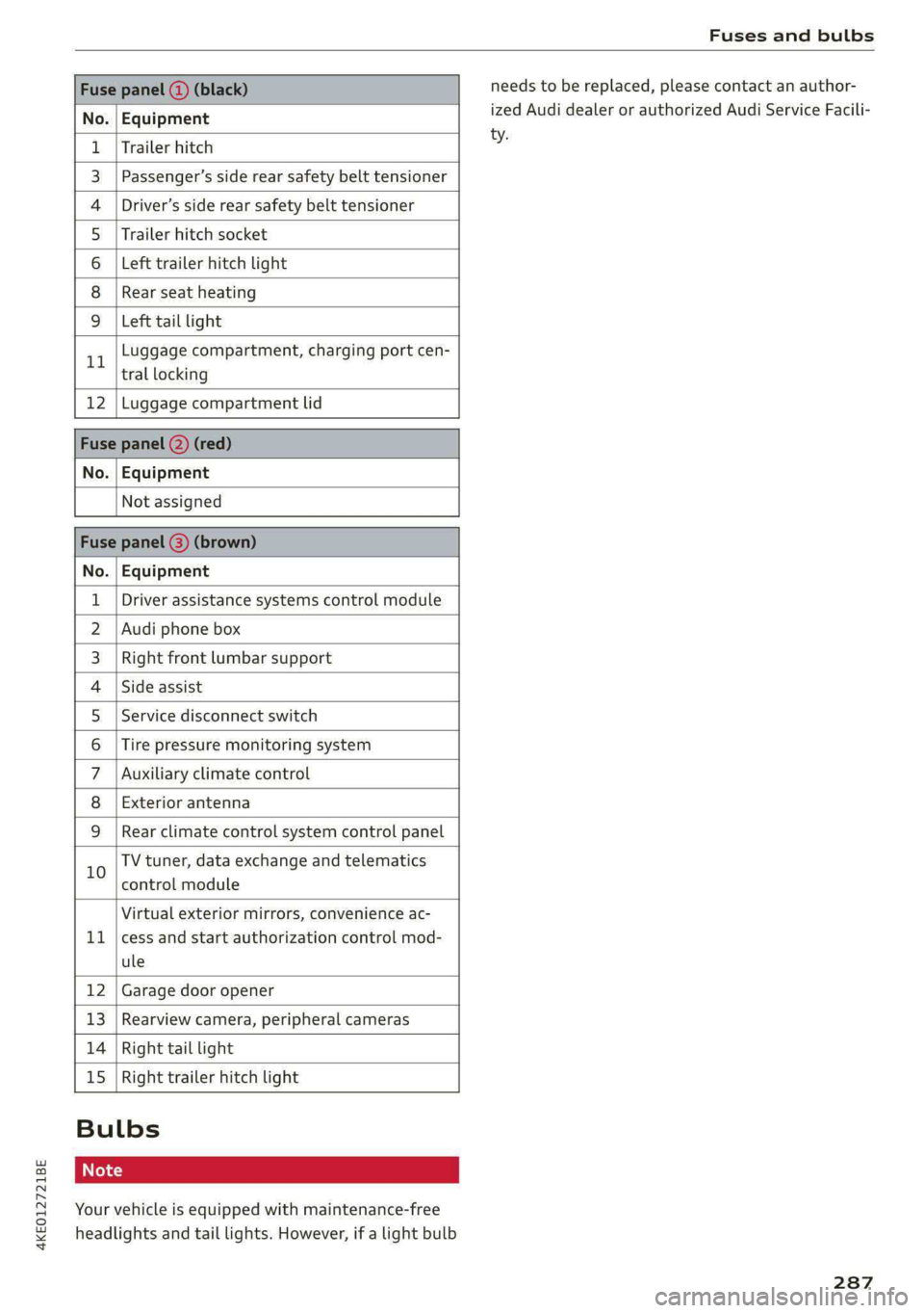
Fuse panel (3) (black)
No. Equipment
Trailer hitch
Passenger’s side rear safety belt tensioner
Driver’s side rear safety belt tensioner
Trailer hitch socket
Left trailer hitch light
Rear seat heating
Ola;
AD)
M/A]
W]e
Left tail light
Luggage compartment, charging port cen-
11 tral locking
12 | Luggage compartment lid
Fuse panel @) (red)
No. | Equipment
Not assigned
Fuse panel (8) (brown)
No. | Equipment
1 | Driver assistance systems control module
2 | Audi phone box
3 | Right front lumbar support
4 | Side assist
5 | Service disconnect switch
6 |Tire pressure monitoring system
7 |Auxiliary climate control
8 | Exterior antenna
9 | Rear climate control system control panel
Bb oO
TV tuner, data exchange and telematics
control module
LL
Virtual exterior mirrors, convenience ac-
cess and start authorization control mod-
ule
12 Garage door opener
13. Rearview camera, peripheral cameras
14 Right tail light
15
Right trailer hitch light
Bulbs
Your vehicle is equipped with maintenance-free
headlights and tail lights. However, if a light bulb
needs to be replaced, please contact an author-
ized Audi dealer or authorized Audi Service Facili-
ty.
287
Page 290 of 316

Data privacy
Data privacy
Image recording
Surrounding area monitoring
Applies to: vehicles with surrounding area monitoring
Some vehicle functions require the vehicle’s path
to be detected and evaluated. This is done by
cameras installed permanently on the vehicle
that detect objects in the vehicle's surroundings
(such as obstacles or guard rails). The live images
from the cameras are transmitted to the applica-
ble control module.
The camera images are transferred to the respon-
sible control module for processing and may be
stored, depending on vehicle equipment. The
control
module analyzes the current camera im-
age using image evaluation software. This image
evaluation software detects anonymized techni-
cal measurements, such as distances to objects.
The control module evaluates these technical
measurements and makes it possible for the as-
sist systems to control the vehicle, if necessary.
Data memories
odules
rt 1 oO g|
= +
a
Fig. 184 Driver's side footwell: connection port for the On
Board Diagnostic System (OBD)
Your vehicle is equipped with electronic control
modules for various vehicle systems such as the
airbags. These vehicle control modules store data
while driving normally that is required by an au-
thorized Audi dealer or authorized Audi Service
Facility for diagnosis and repair purposes. Only
certain types of data are recorded for a very short
period of time if a control module has detected a
288
system event. No noises, conversations, or im-
ages will be recorded in the vehicle.
The data may include information such as the ve-
hicle speed, the direction of travel, and informa-
tion about the brake system, or also the behavior
of the restraint system in the event of an acci-
dent. The stored data can be exported and down-
loaded with special devices, which must be con-
nected directly to the vehicle.
On Board Diagnostic System (OBD)
There is a diagnostic connector socket in the driv-
er's side footwell to read out the various control
modules and the event data recorder. Data re-
garding the function and condition of the elec-
tronic control modules is stored in the event
memory. Only have an authorized Audi dealer or
authorized Audi Service Facility read out and de-
lete the event memory.
Z\ WARNING
— Incorrect use of the connection port for the
On Board Diagnostic System can cause mal-
functions, which can then result in accidents
and serious injuries.
— Only allow an authorized Audi dealer or au-
thorized Audi Service Facility to read out the
motor data.
(air) ata recorder
Event Data Recorder
This vehicle is equipped with an Event Data Re-
corder (EDR). The main purpose of an EDR is to
record, in certain crash or near crash-like situa-
tions,
such as an airbag deployment or hitting a
road obstacle, data that will assist in understand-
ing how a vehicle's system performed. The EDR is
designed to record data related to vehicle dynam-
ics and safety systems for a short period of time,
typically 30 seconds or less. The EDR in this vehi-
cle is designed to record such data as:
— How various systems in your vehicle were oper-
ating;
— Whether or not the driver and passenger safety
belts were buckled/fastened;