AUDI Q5 2015 Owners Manual
Manufacturer: AUDI, Model Year: 2015, Model line: Q5, Model: AUDI Q5 2015Pages: 302, PDF Size: 75.01 MB
Page 261 of 302

M N
co ~ co
rl I.O
"' N
"' rl
Performing the repair
Applies to vehicles: with tire repair kit
Fig. 215 Perfo rm ing the repa ir
Prep arati ons
"' Park the vehicle as far as possib le from moving
traff ic in the event of a flat tire.
"' Set the
parki ng brak e to prevent the vehicle
from roll ing unintentionally.
"' Shift the
sele ctor lever into th e P po sition .
"'Determ ine whethe r a repair w ith the t ire repair
k it is possib le or not
c::> page 258.
"' Let all of the passengers ex it the vehicle and
move a safe d istance away
c::> .&_ .
• Take the se alant bottle and the compre ssor out
of the luggage compartment
i:::> page 105,
fig. 115 .
"'Affix the label "max. 50 mph (80 km/h)", found
on the sealant bottle, to the instrument cluster
where it can be seen by the dr iver.
F illing a tire
"'Shake the bottle thoroughly before fi lling.
"' Screw the accompanying filling hose complete-
ly onto the bottle. This breaks throug h the foil
seal automatically at the connection .
"' Remove the valve cap from the tire va lve and
unscrew the valve insert us ing the accompany
ing valve insert tool~
fig. 215.
"'Lay the valve inse rt o n a clean s urface.
"' Remove the sealing plug from the filling hose
and connect the hose to the tire valve.
"' Hold the bottle with the bottom facing upward
and empty the ent ire contents into the tire.
"' Then pull out the hose and screw the valve in
sert tightly back into the t ire va lve.
Em erg en cy ass is tan ce
Inflating a tire
"'Screw the fill ing hose for the compressor onto
the t ire va lve and insert the connector into the
cigarette lighter.
• Inflate the tire to between 29 PSI (200 kPA)
and 36 PSI (250 kPA) and read the pressure on
the gauge.
"' If this tire pressure is not reached, dr ive your
veh icle app rox imately 33 ft (10 meters) for
ward or backward so that the sealant can be re distr ibuted ins ide the tire . If at th is time the re
qui red a ir pressure st ill canno t be reached, the
t ire is too badly damaged and cannot be re
pa ired with the tire sealant.
Final inspection
"' Stop the vehicle after driving for about 10 mi
nutes and che ck the t ire p ress ure .
"'I f the tire pressure is lower than 19 PSI
( 1 30 kPA), then the tire is too seve rely dam
aged. Do not continue driving . Please seek pro
fessiona l assistance .
A WARNING
-
- Turn on the emergency flashers if you have a
flat tire while in moving traffic. This is for
your protection and the for the safety of
other drivers .
- Take care to move all of the passengers to a
safe place (behind a guard rail for examp le).
- Read and follow the manufacturer's safety
precautions on the compressor and in the instructions on the bottle of sealant!
- If a tire pressure of 29 PSI (200 kPA) cannot
reached after inflating for 12 minutes, then
the t ire is too severely damaged . Do not
continue dr iv ing .
- Obta in qualified help if it is not possible to
perform t he repair w ith the t ire sea lant.
- If the tire pressure is less than 19 PSI
(130 kPA) after 10 minutes of drivi ng, then
the t ire is too severe ly damaged . Do not
continue dr iv ing. See k professiona l assis
tance .
259
Page 262 of 302
Emerg enc y ass is tance
CJ) Note
Special care is required if you are repairing the
tire on a steep incline.
@ Tips
- Do not operate the compressor for more
than 12 minutes continuously, otherwise it
can overheat . Once the compressor has
cooled, you can continue to use it.
- If sealant has spi lled out, let it dry and then
you can remove it by peeling it away like a
foil.
- Remember to obtain a new bottle of sea lant
from yo ur authorized Aud i dea ler after re
pairing a tire. After this, the functionality of
the tire repa ir set is restored.
- Obey all laws.
Replacing wheels
Before changing a wheel
Observe the following precautions for your own
and your passenger's safety when changing a
wheel.
.. After you experience a tire fa ilure, pull the car
well away from moving traffic and try to reach
l eve l ground before you stop¢_& .
.. All passengers sho uld
le ave t he car and move
to a safe location (for instance, behind the
guardrail)¢ _&.
.. Engage the
parking br ake to prevent your vehi
cle from rolling unintentionally¢_& .
.. Move
select or lever to pos itio n P ¢ &_ .
.. If you are tow ing a trailer: unhitch the trailer
from your vehicle .
.. Block the diagonally opposite wheel with the
folding chocks or other objects.
.. Take the
jack * and the in flat abl e s par e tir e*
out of the luggage compartment¢ page 255.
A WARNING
You or your passengers could be injured while
changing a wheel if you do not follow these
safety precautions:
- If you have a flat tire, move a safe distance
off the road. Turn off the engine, t urn the
260
emergency flashers on and use other warn
ing dev ices to alert other motor ists.
- Make sure that passengers wait in a safe
place away from the vehicle and well away
from the road and traffic.
- To help prevent the vehicle from moving
suddenly and possibly slipping off the jack*,
always fully set the parking brake and block
the wheel diagonally opposite the wheel be
ing changed with the folding chocks or oth
er objects. When one front wheel is lifted
off the ground, placing the Automatic Tra ns
m iss ion in P (Pa rk) w ill
not prevent the veh i
cle from moving.
- Before you change a whee l, be sure the
ground is level and firm.
If necessary, use a
sturdy board under the jack *.
- Always store the vehicle tool kit, the jack*
and the replaced tire in the luggage com
pa rtment
¢ page 140.
Changing a wheel
When you change a wheel, follow the sequence
described below step-by-step and in exactly that
order .
1. Remove the d eco rativ e wheel cover*. For
more details see also¢
page 261, Decora
tive wheel covers
or ¢ page 261, Wheels
with wheel bolt caps .
2. Loosen the wheel bolts¢ page 261 .
3. Locate the proper mounting point for the
jack* and align the jack* be low that point
¢ page 262.
4. Lift the car with the jack*¢ page 262 .
5 . Remove the
wheel with th e flat tire and then
install the
inflatable spa re ti re*
¢ page 263.
6. Tig hte n a ll whee l bolts ligh tly .
7 .
Lo we r the vehicle with the jack* .
8 . Use the wheel bolt wrench and
firml y tighten
all wheel bolts ¢
page 261.
9. Replace the decorative wheel co ve r* . ...
Page 263 of 302
M N
co ~ co
rl I.O
"' N
"' rl
_& WARNING
Always read and follow all WARNINGS and in
formation
c> A in Raising the vehicle on
page 262
and c> page 264 .
After changing a wheel
A wheel change i s no t comple te withou t the do
ing the following .
.. Always store the vehicle tool kit, the jack* and
the replaced tire in the luggage compartmen t
c>page 140 .
.. As soon as possible, have the tightening tor
ques
on all wheel bolts checked w ith a torque
wrench . The correct tightening torque is
105
ft lb (140 Nm) .
.. Have the flat tire
replaced as soo n as poss ible.
{1) Tips
- If you notice that the wheel bolts are cor
roded and diffi cult to turn while changing a
tire, they should be replaced before you
check the tightening torque.
- Drive at reduced speed until you have the
tightening torques checked .
Decorative wheel covers
Applies to vehicles: with decorative wheel covers
The decorative wheel covers must be removed
first to access the wheel bolts .
Fig. 216 Chan gin g a wheel: Removing the wheel cove r
Removing
.. Insert the hook provided with the veh icle tool
kit in the hole in the hub.
.. Pull off the
decorative wheel cover c> fig. 216.
Emergen cy assistance
Wheels with wheel bolt caps
Applies to vehicles: with wheel bolts with caps
The cops must be removed firs t from the wheel
bolts before the bolts can be unscrewed .
Fig. 217 Changing a wh eel: re movin g the wheel bo lt ca ps
Removing
.. Push the plastic clip provided wi th the vehicle
too l kit over the wheel bolt cap until it engages.
.. Pull on the
plastic clip to remove the cap
c>fig. 217.
Refitting
.,. Place the caps over the wheel bolts and push
t hem back on.
The caps are to protect and keep the wheel bolts
clean.
Loosening and tightening the wheel bolts
The wheel bolts must be loosened before raising
the vehicle .
Fig. 218 Changing a whe el: loosening th e w hee l bol ts
Loosening
.. Insta ll the wheel bolt wrench over the wheel
bolt and push it down as far as it will go. ..,.
261
Page 264 of 302
Emergency assistance
... Take tight hold of the end of the wrench handle
and turn the wheel bolts
counter-clockwise
about one single turn in the direction of arrow
c::> fig . 218.
Tightening
" Install the wheel bolt wrench over the wheel
bolt and push it down as far as it will go .
... Take tight hold of the
end of the wrench handle
and turn each wheel bolt
clockwise until it is
seated.
A WARNING
- Do not use force or hurry when changing a
wheel -you can cause the vehicle to slip off
the jack* and cause serious personal inju
ries.
- Do not loosen the wheel bolts more than
one turn
before you raise the vehicle with
the jack*. - You risk an injury.
{D) Tips
If a wheel bolt is very tight, you may find it
easier to loosen by carefully pushing down on
the end of the wheel bolt wrench with
one
foot only.
As you do so, hold on to the car to
keep your balance and take care not to slip.
Raising the vehicle
The vehicle must be li~ed with the jack* first be
fore the wheel can be removed.
Fig. 219 Sill panels: mark in gs
262
Fig. 220 Sill: posi tioning the jack
... Engage the parking brake to prevent your vehi
cle from rolling unintentionally
... Move the
selector lever to position P.
... Find the marking (imprint) on the sill that is
nearest the wheel that will be changed
c::> fig. 219 . Behind the marking, there is a lift
ing point
on the sill for the jack*.
"Turn the
jack* located under the lifting point on
the sill to raise the jack until its arm @
c::> fig. 220 is located under the designated plas
tic mount
c::> &. c::>(j).
... Align the jack* so that its arm @ c::> fig. 220 en
gages in the designated lifting point in the door
sill and the movable base ® lies flat on the
ground. The base ® must be
vertical under the
lifting point @.
"Wind the jack* up further until the flat tire
comes off the ground
c::> ,&. .
Position the jack* only under the designated lift
ing points on the sill
c::> fig. 219. There is exactly
one location for each wheel. The jack* must not
be positioned at any other location
c::> .&. c::>(D.
An unstable surface under the jack* can cause
the vehicle to slip off the jack* . Always provide a
firm base for the jack* on the ground . If necessa
ry place a sturdy board or similar support under
the jack*. On
hard, slippery surfaces (such as
tiles) use a rubber mat or similar to prevent the
jack* from slipping
c::> ,&..
A WARNING -
-You or your passengers could be injured
while changing a wheel if you do not follow
these safety precautions:
Page 265 of 302
M N
co ~ co
rl I.O
"' N
"' rl
-Position the jack * only at the designated
lift ing po ints and align the jack* . Other
wise, the jack* could slip and cause an in
jury if it does not have suffic ient hold on
the vehicle .
- A soft or unstab le surface under the jack*
may cause the vehicle to slip
off the jack*.
Always provide a firm base for the jack * on
the ground. If necessa ry, us e a sturdy
board under t he ja ck*.
- On ha rd, slippery surface (such as til es)
use a rubbe r mat or similar to prevent the
jack* from slipp ing.
- T o help prevent injury to yourself and your
passenge rs:
- Do not raise the vehicle until yo u are sure
the jack* is secure ly engaged.
- Passengers must not remain in the vehicle
when it is jacked up.
- Make sure that passengers wa it in a safe
p lace away from the vehicle and well away
from the road and traffic.
- Make sure jack position is correct, adjust
as necessary and then continue to raise
the jack *.
(D Note
Do not lift the vehicle by the si ll. Pos ition the
jack * only at the designated lifting points on
the si ll. Otherwise, your ve hicle wi ll be dam
aged.
Em erg en cy ass is tan ce
Taking the wheel off /installing the
inflatable spare tire
Follow these instructions step-by-step for chang
ing the wheel
F ig . 22 1 Chang in g a whee l: usin g t he screwdr iver hand le
(w ith the blade re moved) to turn the bolts
Fig . 222 Cha ng ing a w hee l: alig nment pin inside the top
h ole
After you have loosened all wheel bolts and
raised the vehicle off the ground, remove and re
place the wheel as follows:
Removing th e wheel
.,. Use the hexagonal socket in the screwd river
h andle
to comp letely remove the topmost
wheel bo lt and set it aside on a
clean surface
¢fig. 221 .
.,. Screw the threaded end of the alignment pin
from the tool kit hand-tight into the empty bolt
hole
¢ fig . 222 .
.,. Then remove the othe r whee l bolts as described
above .
.,. Ta ke
off the whee l leaving the a lignment pin in
t he bolt hole
c;, (D _
Putting on th e inflatable spare tire*
.,. Inflate the inflatable spare tire* ¢ page 257
and push the wheel over the alignmen t pin.
263
Page 266 of 302
Emergency assistance
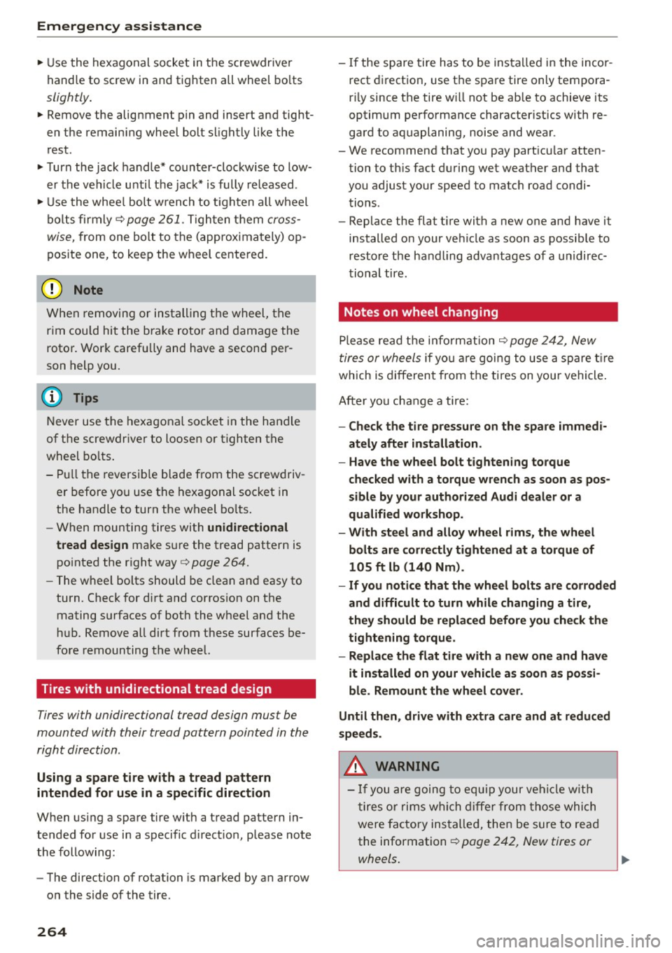
"' Use the hexagonal socket in the screwdriver
handle to screw in and tighten all wheel bolts
slightly.
"'Remove the alignment pin and insert and tight
en the remaining wheel bolt slightly like the
rest.
"'T urn the jack handle* counter-clockwise to low
er the vehicle until the jack* is fully released .
"'U se the whee l bolt wrench to tighten all wheel
bolts firmly¢
page 261. Tighten them cross
wise,
from one bolt to the (approximately) op
posite one, to keep the wheel centered.
@ Note
When removing or installing the wheel, the
r im could hit the brake rotor and damage the
rotor. Work carefu lly and have a second per
son help you.
(D Tips
Never use the hexagonal socket in the handle
of the screwdriver to loosen or tighten the
wheel bolts.
- Pull the reversib le blade from the screwdriv
er before you use the hexagonal socket in
the handle to turn the wheel bolts.
- When mounting tires with
unidirectional
tread design
make sure the tread pattern is
pointed the right way
¢page 264.
-The wheel bolts should be clean and easy to
turn. Check for dirt and corrosion on the
mating surfaces of bot h the wheel and the
hub. Remove all dirt from these surfaces be
fore remounting the wheel.
Tires with unidirectional tread design
Tires with unidirectional tread design must be
mounted with their tread pattern pointed in the
right direction.
Using a spare tire with a tread pattern
intended for use in a specific direction
When us ing a spare tire w ith a tread pattern in
tended for use in a specific direct ion, please note
the following:
- The direction of rotation is marked by an arrow
on the side of the tire .
264
-If the spare tire has to be installed in the incor
rect direction, use the spare tire only tempora
r il y since the tire w ill not be ab le to achieve its
optimum performance character istics with re
gard to aquaplaning, noise and wear.
- We recommend that you pay part icu lar atten
tion to th is fact during wet weather and that
you adjust your speed to match road condi
tions.
- Replace the flat tire with a new one and have it
installed on your veh icle as soon as possible to
resto re the handling advantages of a unidirec
tional tire.
Notes on wheel changing
Please read the information ¢ page 242, New
tires ar wheels
if you are going to use a spare tire
which is different from the tires on your vehicle .
After you change a tire:
- Check the tire pressure on the spare immedi
ately after installation.
- Have the wheel bolt tightening torque
checked with a torque wrench as soon as pos
sible by your authorized Audi dealer or a
qualified workshop.
- With steel and alloy wheel rims, the wheel
bolts are correctly tightened at a torque of
105 ft lb (140 Nm).
- If you notice that the wheel bolts are corroded
and difficult to turn while changing a tire,
they should be replaced before you check the
tightening torque.
- Replace the flat tire with a new one and have
it installed on your vehicle as soon as possi
ble. Remount the wheel cover.
Until then, drive with extra care and at reduced
speeds.
&_ WARNING
- If you are going to equ ip your vehi cle w ith
tires or rims which differ from those which
were factory installed, then be sure to read
the information ¢
page 242, New tires or
wheels .
-
Page 267 of 302
M N
co
a:
co
,...., \!) ..,.,
N ..,., ,....,
-Always make sure the damaged wheel or
even a flat tire and the jack* and tool kit are
properly secured in the luggage compart
ment and are not loose in the passenger
compartment .
- In an accident or sudden maneuver they
could fly forward, injuring anyone in the ve
hicle.
- Always store damaged wheel, jack* and
tools securely in the luggage compartment .
Otherw ise, in an acc ident or sudden maneu
ver they could fly forward, causing injury to
passengers in the vehicle.
Emergency assistance
265
Page 268 of 302
Fuses and bulbs
Fuses and bulbs
Fuses
Replacing fuses
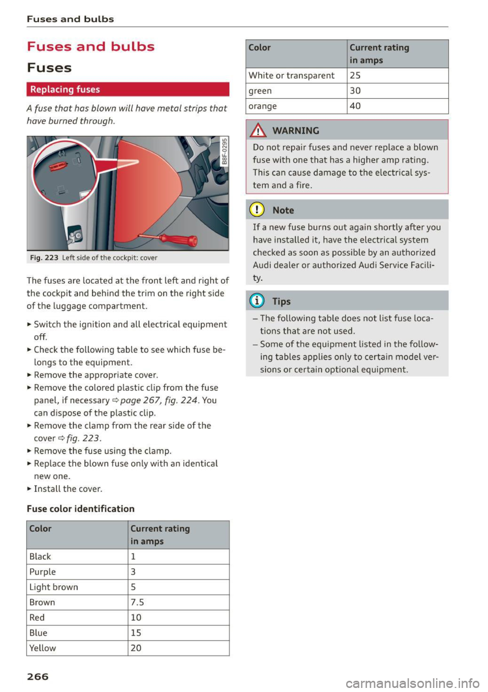
A fuse that has blown will have me tal strips that
have burned through.
Fig. 2 23 Left side of the coc kp it: c ove r
The fuses a re located at the fron t left and right of
the cockpit and behind the trim on the right side
of the luggage compartment.
• Swi tc h the ign ition and all e lec trica l equipment
off .
• Check the following table to see which fuse be
longs to the equipment.
• Remove the appropriate cover.
~ Remove the colored p lastic clip from the fuse
panel, if necessary ¢
page 267, fig. 224. You
can d ispose of the p lastic clip .
• Remove the clamp from the rear side of the
c over ¢
fig. 223 .
• Remove the fuse using the clamp.
• Rep lace the blow n fuse o nly w it h a n ident ica l
new one.
• Install the cover .
Fuse color identification
Color Current
rating
in amps
B lack 1
Purp le
3
Light brown
s
Brown 7.5
R ed 10
B lue 15
Yellow 20
266
Color Current rating
in amps
W hite or transparent
2S
green 30
orange 40
A WARNING
Do not repair fuses and never replace a blown
fuse with one tha t has a hig her amp rating.
T hi s ca n cau se da mage to the e lec trica l sy s
tem and a fire .
(D Note
If a new fuse burns out again sho rtly after you
have install ed it, have th e electri cal syst em
che cked as soon as possib le by an autho rize d
A udi dealer or au tho riz ed Au di Service Facili
ty .
{i) Tips
- T he followi ng tab le does not list fuse loca
tion s that a re n ot u sed .
- Some of the e quipment listed in the fo llow
ing table s applies on ly to cert ain model ve r
si ons or certain op tion al equi pment .
Page 269 of 302

M N
co ~ co
rl I.O
"' N
"' rl
Left cockpit fuse assignment
Fig. 224 Left side of the cockpit: fuse panel with plastic
clip
Fuse panel @ (black )
No. Equipment
1 Dynamic steering
2 ESC control module
A/C system pressure sensor, electrome-
3 chanical park
ing brake, Homelink, auto-
matic dimming interior rearview mirror, air
quality/outside air sensor, ESC button
5 Sound
actuator/exhaust sound tuning
6 Headlight range contro l/cornering light
7 Headlight (cornering light)
Control modu les (e lectromechanical park-
8 ing brake, shock absorber, quattro Sport,
trailer hitch), DCDC converter
9
Adaptive cruise control or high voltage
battery (hybrid drive)
11 Side assist
12 Headlight range control, parking system
13 Airbag
14 Rear w iper
15 Auxi
liary fuse (instrument panel)
1 6 Auxiliary fuse terminal 15 (engine area) Fuses
and bulbs
Fuse panel @ (brown)
No . Equipment
1 Electric exhaust door
2 Brake light sensor or brake pedal
move-
ment sensor (hybr id drive)
3 Fuel pump
4 AdBlue pumps
or brake booster power
supply (hybrid dr ive)
5 Left seat heating with/without seat venti-
lation
6 ESC
7 Horn
8 Left
front door (window regulator, central
locking, mirror, switch, lighting)
9 Wiper motor
10 ESC
11 Left
rear door (window regu lator, switch,
lighting)
12 Rain and light sensor
Fu
se panel © (re d)
No . Equipment
3 Lumbar support
4 Dynamic steering
5 Climatized cupholder
6 Windshie
ld washer system, headlamp
washer system
7 Vehicle electr ical system control module 1
8 Vehicle e
lectrica l system control module 1
9 Panorama sunroof
10 Vehicle e lectrica l system control module 1
11 Sun shade (pano rama sunroof)
12 Anti-theft a
larm system
267
Page 270 of 302
Fuses and bulbs
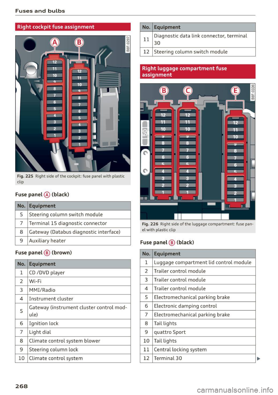
Right cockpit fuse assignment
Fig . 225 Right s ide of the cockpit: fuse panel wit h plastic
clip
Fuse panel @ (black)
No. Equipment
5 Steering column sw
itch module
7 Terminal 15 diagnostic connector
8 Gateway (Oatabus diagnostic interface)
9 Auxiliary heater
Fuse panel@ (brown)
No. Equipment
1 CD /DVD player
2 Wi-Fi
3 MM I/Radio
4 Instrument cluster
5
Gateway (instrument cluster control mod-
ule)
6 Ignition lock
7 Light dial
8 Climate control system blower
9 Steering column lock
10 Climate control system
268
No. Equipment
11 D
iagnost ic data link connecto r, terminal
30
12 Steering column switch module
Right luggage compartment fuse
assignment
Fig. 226 Righ t side of the lu ggage compartment: fuse pan
e l w ith plastic clip
Fuse panel @ (black)
No. Equipment
1 Luggag e compartm ent lid control module
2 Trailer contro
l module
3 Trailer con trol module
4 Trailer control module
s Elec trom echanica l parking brake
6 E lectronic damping control
7 Electromechanical parking brake
8 Tail lights
9 quattro Sport
10 Tail lights
11 Central locking
system
12 Termina l 30