display AUDI Q7 2013 Owner´s Manual
[x] Cancel search | Manufacturer: AUDI, Model Year: 2013, Model line: Q7, Model: AUDI Q7 2013Pages: 348, PDF Size: 87.72 MB
Page 253 of 348
Your authorized Audi dealer can provide cleaning products that have been tested and ap
proved for your vehicle .
Care of interior
MMI display
"' Clean the MMI disp lay with a soft clean
cloth and an LCD cleaner .
The MMI display can be cleaned with a profes sionally available "LCD cleaner". The cloth
should be s light ly dampened with the clean
ing f lu id to clean the display.
(D Note
To avo id scratching the MM I display, you
should never clean it d ry.
MMI control console
"' First clean the MMI control console with a
brush to remove dust from the housing.
"' Then wipe the MMI contro l conso le with a
clean, soft, slightly damp cloth .
The MM I control console shou ld be cleaned
with a brush first so that no dirt is trapped be
tween the buttons and the housing. We rec ommend giv ing the MMI control console a fi
nal w ipe with a cloth mo istened with water
and d ish washing detergent.
Cl) Note
To prevent damage, make sure that no flu id ever gets into the MMI control console.
Aluminum trim
Use only neutral-pH products to remove spots
and depos its from alum inum surfaces .
C hr ome ca re produ cts and alkaline cleaners
will attac k alum in um s urfaces and can dam
age them ove r time.
A WARNING
Always read and heed a ll WARNINGS and
other information
~ page 245 .
Cleaning and protec tion 25 1
Fabrics and fabric coverings
Fabr ics and fab ric cover ings (e.g. seats, door
trim pa ne ls, etc.) sho uld be cleaned at regular
intervals w ith a vacuum cleaner . This removes
s u rface dirt particles which could become em
bedded in the fabric throug h use. Steam
cleaners should not be used, because the
steam tends to push the dirt deeper into the
fabric and lock it there.
No rmal cl ean ing
Generally, we recommend using a soft sponge
or a lint-free microfiber cloth to the clean fab ric . Brushes shou ld only be used for carpets
and floor mats, since other fabr ic surfaces
could be harmed by brushes.
Normal s urface stains can be cleaned using a
commerc ially available foam cleaner. Spread
the foam on the surface of the fabric with a
soft sponge and work it in gently. Do not satu
rate the fabric. Then pat the foam dry us ing
absorbent, dry cloths (e.g. m icrofiber cloth)
and vacuum it after it has dried completely.
Cleaning sta in s
Stains caused by beverages (e.g. coffee, fruit
juice, etc.) can be treated with a mild deter gent solution . Apply the detergent solution
with a sponge . In the case of stubborn stains,
a dete rgent paste can be applied directly to
the stain and worked into the fabric . After
wards, use copious amoun ts of clean wa ter to
remove the rema ining de tergent. App ly the
water with a damp cloth or sponge and pat
the fabric dry with an absorbent, dry clot h.
Stains from choco late or ma keup sho uld have
detergent paste (e.g . ox-gall soap) rubbed in
to them. Afterwards, remove the soap with
water (damp sponge) .
A lcohol can be used to treat sta ins from
grease, o il, lipstick or a ballpoint pen. Melted
grease or dye must be patted off using ab
sorbent mater ial. It may be necessary to re
treat the areas with detergent paste and wa
ter.
•
•
Page 263 of 348
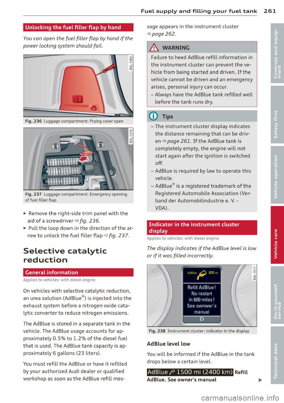
Unlocking the fuel filler flap by hand
You can open the fuel filler flap by hand if the
power locking system should fail.
•
•
Fig . 236 Luggage compartment: Prying cover open
Fi g. 237 Luggage compartment: Emergency opening
of fuel filler flap
.. Remove the right-side trim panel with the
aid of a screwdriver ¢
fig. 236.
.. Pull the loop down in the direction of the ar
row to unlock the fuel f iller flap ¢
fig. 237.
Selective catalytic
reduction
General information
App lies to vehicles : with diesel engine
On vehicles w ith select ive catalytic reduction,
an urea solut ion (Ad Blue ®) is injected into the
exhaust system befo re a nitrogen oxide cata
lytic converter to reduce nitrogen em iss ions.
The AdBlue is stored in a separate tank in the
veh icle. The AdBlue usage accounts for ap
p rox imately 0.5% to 1.2% of the diese l fuel
that is used. The Ad Blue tank capaci ty is ap
pr ox ima tely 6 gallons (23 liters).
You must refill the Ad Blue or have it refilled
by your authorized A udi dealer or qualified
wo rkshop as soon as the Ad Bl ue refill mes-
Fu el suppl y and filli ng your fuel t ank 261
sage appears in the instrument cluster
¢ page 262.
A WARNING
Failure to heed AdBlue refill info rmation in
the instrument cluster can prevent the ve hi cle from be ing started and dr iven. If the
vehicle cannot be driven and a n emerge ncy
a rises, pe rsonal injury can occur.
- Always have the AdBlue tank refilled well
befo re the tank runs dry .
(D Tips
- The instrument cluster d isp lay ind icates
the distance remain ing that can be driv
en ¢
page 261. If the Ad B lue tank is
completely empty, the engine will not
start again afte r the ignit ion is switched
off.
- Ad Blue is req uired by law to operate th is
veh icl e.
- Ad Blue ® is a registered trademark of the
Registe red Automobile Association (Ve r
band de r Automob ilindustrie e.
V. -
VOA) .
Indicator in the instrument cluster
display
Appl ies to vehicles: wit h diesel eng ine
The display indica tes if the Ad Blue level is low
or if it was filled incorrectly.
Fi g. 2 38 Instr ument cluste r: indicator in t he d isplay
AdBlue level low
You w ill be informed if t he AdB lue in the tank
drops below a certain level.
Ad Blue /9 1500 mi (2400 km) R efill
AdBlue. See owner 's manual
Page 264 of 348
262 Fuel supply and filling your fuel tank
This indicator appears when there is only
enough Ad B lue left to drive the distance indi
cated in the driver information system. Please
add Ad Blue.
Ad Bluel~ 600 mi (1000 km) Refill
AdBlue! No restart in 600 miles (1000 km)!
See owner's manual
This indicato r appears when there is only
enough Ad B lue left to drive the distance indi
cated in the driver information system. Please
add Ad B lue. Otherw ise the eng ine will not
start again if you stop it once the distance in
d icated has been driven.
Refill Ad Blue! No
restart! See owner's manual
This message appears when the AdBlue tank
i s empty . Please add AdBlue. Otherwise you
will not be able to start the engine again once
you stop it.
When the minimum AdB lue leve l has been
reached, you must add Ad Blue ¢
page 262.
¢111ij Filling incorrectly
If the Ad B lue tank was filled with a diffe rent
f luid than Ad Blue and the system detects that
it is incorrect, a message w ill appear.
AdBlue ,/ 600 mi (1000 km) Ad Blue!
No re start in 600 miles (1000 km)! See own·
er's manual
This message appears when it is only poss ible
to drive the distance indicated in the dr iver in
formation system . Drive to the nearest quali
fied workshop to have the malfunction re-
pa ired . Otherwise the engine will not start
a ga in if you stop it once the distance indicated
has been driven.
AdBlue: system
fault. No restart! See owner's manual
This message appears if the system detects it
was filled incorrectly . Drive immed iate ly to
the nearest qualified workshop to have the
malfunction repaired. Otherwise you will not
be able to start the engine again once you
stop it.
Filling AdBlue
Applies to vehicles: with diesel engine
A special refill bottle must be used to fill the
AdBlue .
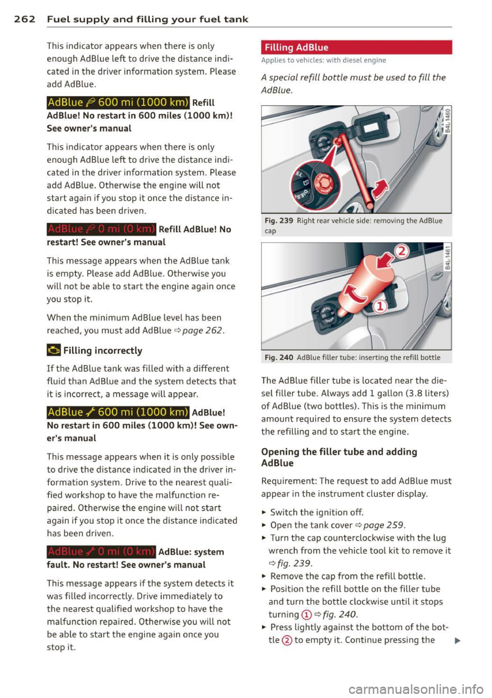
Fig. 239 Right rear veh icle s ide: removing t he AdB lue
cap
Fig. 240 AdB lu e fille r tube: insert ing the refill bott le
The Ad Blue filler tube is located near the die
sel filler tube. Always add 1 gallon (3.8 liters)
of Ad Blue (two bottles) . This is the minimum
amount required to ensure the system detects
the refilling and to start the engine .
Opening the filler tube and adding
AdBlue
Requirement: The request to add Ad Blue must
appear in the instrument cluster display.
.,. Switch the ignition off.
.,. Open the tank cover¢
page 259.
.,. Tu rn the cap counterclockwise with the lug
w rench from the vehicle tool kit to remove it
¢fig. 239.
.,. Remove the cap from the refill bottle.
.,. Position the refill bottle on the filler tube
and turn the bottle clockwise until it stops
turning @¢
fig. 240.
.,. Press lightly against the bottom of the bot-
tle @to empty it . Continue pressing the ..,.
Page 265 of 348
bottom of the bottle until it is empty or
until fluid stops f lowing into the tank.
~ Turn the bott le to the left without press ing
on the bottom.
Closing the filler tube
~ Turn the cap clockwise on the filler tube
with the lug wrench until you hear it tighten
completely.
~ Close the tank cover .
After filling
The vehicle must be driven . The system may
take up to two minutes to detect that the
Ad B lue has been filled.
~ If there was no AdBlue left in the tank and a
range of
O mi (0 km ) was displayed in the
instrument cluster, switch the ignition on
for about 15 seconds before starting the en
gine .
.&_ WARNING
Ad Blue can irritate the skin, eyes and res
piratory system. If there is contact with
the fluid, flush immediately with plenty of
water . Consult a physician if necessary .
(D Note
-Only use Ad Blue that conforms to the
standard ISO 22241-1. Do not mix any
additives with the Ad Blue and do not di
lute it with water .
- Ad Blue is not a diesel additive. Do not
add it to the diesel tank. If Ad Blue is
mixed w ith diesel fuel, it can lead to
damage to the eng ine and the Ad Blue
tank system . The Limited New Vehicle
Warranty does not cover such damage.
- AdBlue attacks surfaces such as painted
vehicle components, plast ic and carpet.
Remove the fluid as quick ly as possible
with a damp cloth and plenty of cold wa
ter . If the AdBlue has already crystal
lized, use warm water and a sponge.
AdBlue residue that is not removed w ill
crystall ize and can damage the affected
surface .
Fuel supply and filling your fuel tank 263
-Do not store the refill bottle in the vehi
cle . If it leaks, the escaping Ad Blue could
damage the vehicle interior.
- Do not allow Ad Blue to come into con
tact with clothing . If there is contact
with the fluid, flush immediate ly with
plenty of water .
(1) Tips
-Yo u can obtain refill bottles from any au
thorized Audi dealer or other qualified
workshop .
- Follow the Ad Blue manufacturer's in
struct ions for usage and storage. •
•
Page 301 of 348
TPMS malfunction indicator is combined with
the low tire pressure tellta le . When the sys
tem detects a malf unct ion, the te lltale will
flash for approximately one minute and then remain cont inuously illuminated. This se
quence will continue upon subsequent vehicle
start-ups as long as the malfunction ex ists .
When the malfunct ion indicator is illuminat
ed, the system may not be able to detect or
sig nal low t ire pressure as intended . TPMS
malfunct ions may occur for a variety of rea
sons, including the installat ion of rep lace
ment or alternate tires o r whee ls on the veh i
cle that prevent the TPMS from funct io ni ng
p roperly. Always check the TPM S malfunct ion
tellta le after replacing one or more tires or
wheels on your vehicle to ensure that the re p lacement or a lternate tires and wheels allow
the TPMS to continue to function properly.
Tire pressure indicator appears
The tire pressure indicator in the instrument
cluster informs you if the tire pressure is too
low or if there is a system malfunction.
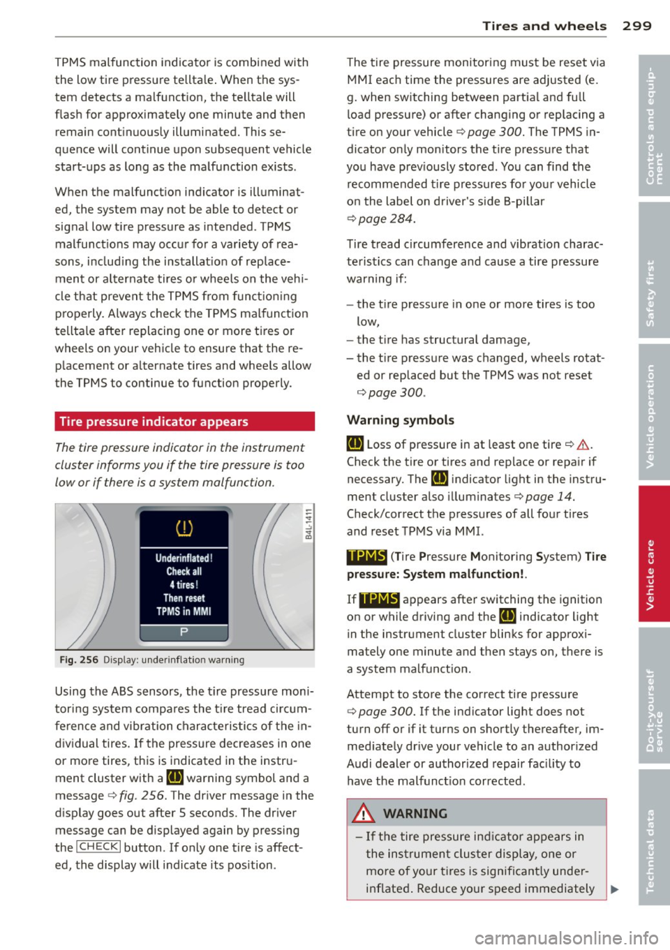
Fi g. 25 6 Display: under inflat io n warn ing
Using the ABS sensors, the tire pressure mon i
tori ng system compa res the t ire tread ci rcum
fe rence and vibration characteristics of the in
dividual tires. If the pressure decreases in one
or more tires, this is indicated in the instr u
ment cluster with a
IE warning symbol and a
message
c:> fig . 256. The driver message in the
d isplay goes out after 5 seconds. The driver
message can be d isplayed again by pressing
the
! CHECK I button . If only one tire is affect
ed, the display will indicate its pos ition .
Tire s an d wheel s 2 99
The t ire pressure monitoring must be reset via
MMI each time the pressures are adjusted (e.
g. when switching between part ia l and full
l oad pressure) or after changing or replacing a
tire on your vehicle
c:> page 300. The TPMS in
dicator on ly monitors the tire pressure that
you have prev iously stored . You can find the
recommended t ire pressures for you r vehicle
o n the label on driver's s ide 8-pillar
¢ page 284.
Tire tread circumference and vibration charac
teristics can change and cause a tire pressure
warning if:
- the t ire pressure in one or more tires is too
low,
- the t ire has structural damage,
- the t ire press ure was changed, wheels rotat-
ed or replaced but the TPMS was not reset
¢page 300.
Warni ng symbo ls
IE Loss of pressure in at least one tire ¢ &..
Check the tire or tires and rep lace or repa ir if
necessary. The
Rt] i ndicator light in the instru
ment cluster also illuminates¢
page 14.
Check/correct the p ressures of all four tires
and reset TPMS via MMI.
••NIB (T ire Pressure Monitoring System) Tir e
pressure: System malfunct ion!.
If llilW appears
after switching the ignition
on or while driving and the
IE indicator light
in the instrument cluster blinks for approxi
mately one minute and then stays on, there is
a system malfunct ion.
Attempt to store the correct tire pressure
¢
page 300. If the indicator light does not
turn off or if it turns on shortly thereafter, im med iate ly dr ive your vehicle to an author ized
Audi dealer or authorized repair fac ility to
have the malfunct ion corrected.
_&, WARNING
- If the tire pressure ind icator appears in
the ins trument cluster display, one or
mo re of your t ires is significant ly under
inflated . Reduce your speed immediately ..,
•
•
Page 313 of 348
Fuse s and bulb s 311
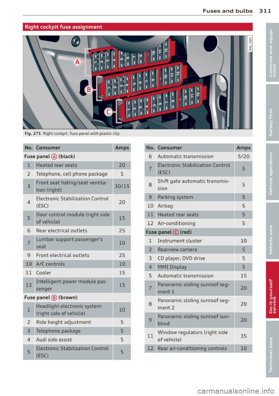
Right cockpit fuse assignment
Fig . 27 1 Righ t cockp it: f use pane l w ith pla stic clip
No. Con sumer Amps No. Consumer Amps
Fu se pa nel@ (bla ck )
6 Automatic transmission
5/20
1 Heated rear seats
7
Electronic Stabilization Control 5
2 Telephone, cell phone package (ESC)
--Shift gate automatic transmis-
Front seat hating/seat ventila-
8 s 3 30/15
tion (right) sion
Electron ic Stab ilizat ion Control
9 Parking system 5
4 (ESC) 20
10 Airbag s
s
Door control module (right side 15 Heated rear seats
5
of vehicle) 12 Ai r·conditioning 5
6 Rear electrical outlets 25 Fuse panel © (red )
7
Lumbar support passenger's
10 1
Instrument cluste r 10
seat 2 Rearview camera 5
9 Front electrical outlets 25
3 CD player, DVD drive s
10 A/C controls 10
MMI Display 5
11 Coo ler 15
5 Automatic transmission 15
I 12 Intelligent power module pas-
15 Panoramic sliding sunroof seg-
senger 7 ment 1 20
Fu
se p anel@ (b rown ) Panoramic sliding sunroof seg-
Headlight electronic system
8 ment 2 20
1 10
(right side of vehicle) Panoramic sliding sunroof sun-
2 Ride height adjustment 5
9 blind 20
5 Window regulators (right side
1 1 35
4 Audi side assist
5 of vehicle)
5 Electronic Stabili
zation Control
5 12 Rear air-conditioning controls
(ESC)
Page 322 of 348
320 General information
General information Explanation of
technical data
Some of the technical data listed in this man
ual requires further explanation .
The technical data for your vehicle is listed in
the charts starting on
r:::>page 322. This sec
tion provides general information, notes and
restrictions which apply to this data .
Vehicle identification
The key data is given on the vehicle identifica
tion number (VIN) plate and the vehicle data
sticker.
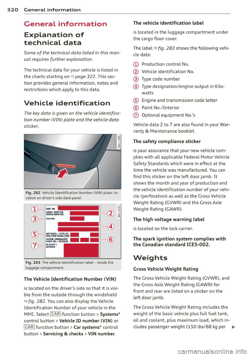
Fig. 282 Veh icle Ide ntific atio n Number (VlN) p late: lo
cation on driver 's sid e das h panel
Fig. 283 The vehicle identi fication label -inside the
luggage co mpa rtmen t
The Vehicle Identification Number (VIN)
is located on the driver's side so that it is visi
b le from the outside through the windshield
r:::> fig . 282 . You can also display the Vehicle
Identification Number of your vehicle in the
MMI. Select !CAR lfunc tion button>
Systems*
control button > Vehicle ID number (V IN) or
ICARI function button >
Car systems * control
button >
Servicing & checks > VIN number . The
vehicle identification label
is located in the luggage compartment under
the cargo floor cover.
The label¢
fig. 283 shows the following vehi
cle data :
(D Production control No .
@ Vehicle identification No.
® Type code number
@ Type designation/engine output in Kilo-
watts
® Engine and transmission code letter
@ Paint No./Interior
(f) Optional equipment No.'s
Vehicle data 2 to 7 are also found in your War
ranty
& Maintenance booklet.
The safety compliance sticker
is you r assurance that your new vehicle com
plies with all applicable Federal Motor Vehicle
Safety Standards which were in effect at the
time the vehicle was manufactured . You can
find this sticker on the left door jamb.
It
shows the month and year of production and
the ve hicle ident ification number of your vehi
cle (perforation) as well as the Gross Vehicle
Weight Rating (GVWR) and the Gross Axle
Weight Rating (GAWR) .
The high voltage warning label
is located on the lock carr ier .
The spark ignition system complies with
the Canadian standard ICES-002.
Weights
Gross Vehicle Weight Rating
The Gross Vehicle Weight Rating (GVWR), and
the Gross Axle Weight Rating (GAWR) for
front and rear are Listed on a sticker on the
left door jamb.
The Gross Vehicle Weight Rating includes the
weight of the basic vehicle plus full fuel tank,
oi l and coolant, plus maximum load, wh ich in
cludes passenger weight (lSO lbs/68 kg per
Ill>
Page 332 of 348
330 Index
A
Accessories
Adaptive A ir Suspension .... ... .. .. .. .
Cargo mode in the MMI .... .. .. .. .. . 327
155
160
Controls ...................... .. . 155
D .. escnpt 1on ... ........... .. .. .... .
H igh level . ............. ... .. .... .
Highway leve l .... ..... ... .. .. .... .
Instrument cluster display ... ... ... .
Jacking mode when changing a flat tire
Low level ................ .... .... . 155
155
155
158
159
155
Normal level ............. .... .... . 155
Segment display ........... .. .. ... 157
Sett ing the driving modes . ... .. .. .. . 157
Trailer towing mode ....... .... .... . 159
Using switch for cargo mode ...... ... 160
Warn ing/ indicator lights ..... .. .... .. 17
Adaptive cruise control .......... .. .. . 113
Changing speed . . . . . . . . . . . . . . . . . . . 11 7
C leaning senso rs .. ....... .. .. .. ... 247
Dr iver info rmation .......... .. .... . 120
Driver intervention prompt . .. .. .. .. . 124
Driving in traffic ................... 114
Driving program . . . . . . . . . . . . . . . . . . . 124
Error messages . . . . . . . . . . . . . . . . . . . 122
Open road .. ............. .. .. .. .. . 114
Override 114
Request for dr iver to assume control . . 114
Save speed ................. ... .. . 116
Setting distance . . . . . . . . . . . . . . . . . . . 118
Settings ... ............. .. .. .. .. . 124
Sett ing t ime interval .......... .... . 118
Specia l dr iv ing s ituations .. .. .. ..... 125
Status messages ........ ... .. .... . 122
Switching on and off ..... ... .. .... . 116
System limits . . . . . . . . . . . . . . . . . . . . . 125
Temporarily turning off .... .. .. .. .. . 118
warn ing/indicator lights ..... .. .... . 121
Adaptive light .......... ... ... ..... .. 59
defective . . . . . . . . . . . . . . . . . . . . . . . . . . 3 7
AdBlue .. .. .. ............. ........ .
261
Filling 262
Messages in the instrument cluster dis-
p lay .. ... ....... ....... ... .. .... .
261
Adding
Engine coolant ... ............ .... .
273
Engine oil 270
Windsh ield washer fluid ........ .... 279
Additional accessor ies
Additives Engine oil
Adjusting 327
270
Instrument cluster illumination .. .. .. . 13
Steering column electrically ..... .. .. 103
Steering column manually .. .. ... ... 103
Adjusting front seats . . . . . . . . . . . . . . . . . 71
Airbag
Warning/ind icator lights ........ .. .. .
16
Airbag system . . . . . . . . . . . . . . . . . 184, 201
Advanced Airbag System ..... ... .. .. 188
Advanced Airbag System components . 191
Care .. .... .... .. ............. .... 198
Children .. .. .. .. ............. .. .. 206
Child restraints ... .............. ... 207
Components (front airbags) ......... 191
Danger of fitting a child safety seat on
the front passenger seat ........ .. ..
186
Disposal .. .... .. ... .......... .... 198
Front airbags . . . . . . . . . . . . . . . . 188, 189
How do the front airbags work? ...... 193
How many a irbags does my vehicle
have? ....... ... .. .............. .
191
How the Advanced Airbag System com-
ponents work togethe r ......... ....
192
Important things to know ........ ... 184
Indicator light ... ............ .... . 195
Monitoring .... .. .......... ... .... 195
PASS ENGER AIR BAG OFF light . .. .. .. 195
Repairs ... .... .. .. ........... .... 198
Safety instructions ............... .. 197
Side airbags . .. .. .......... ...... . 199
Side curtain airbags ...... ...... .. .. 202
Weight-sensing mat .. ... ... ... .. .. 206
When must the system be inspected? . 195
Air conditioning
refer to Climate controls . . . . . . . . . . . . . 91
Air distribution
Climate controls .. ............. .... .
94
Four- zone automatic comfort air condi-
tioning . .. .. .. .. ............. .. .. .
99
Air pollutants filter
Climate controls . ............... ... .
91
Page 336 of 348
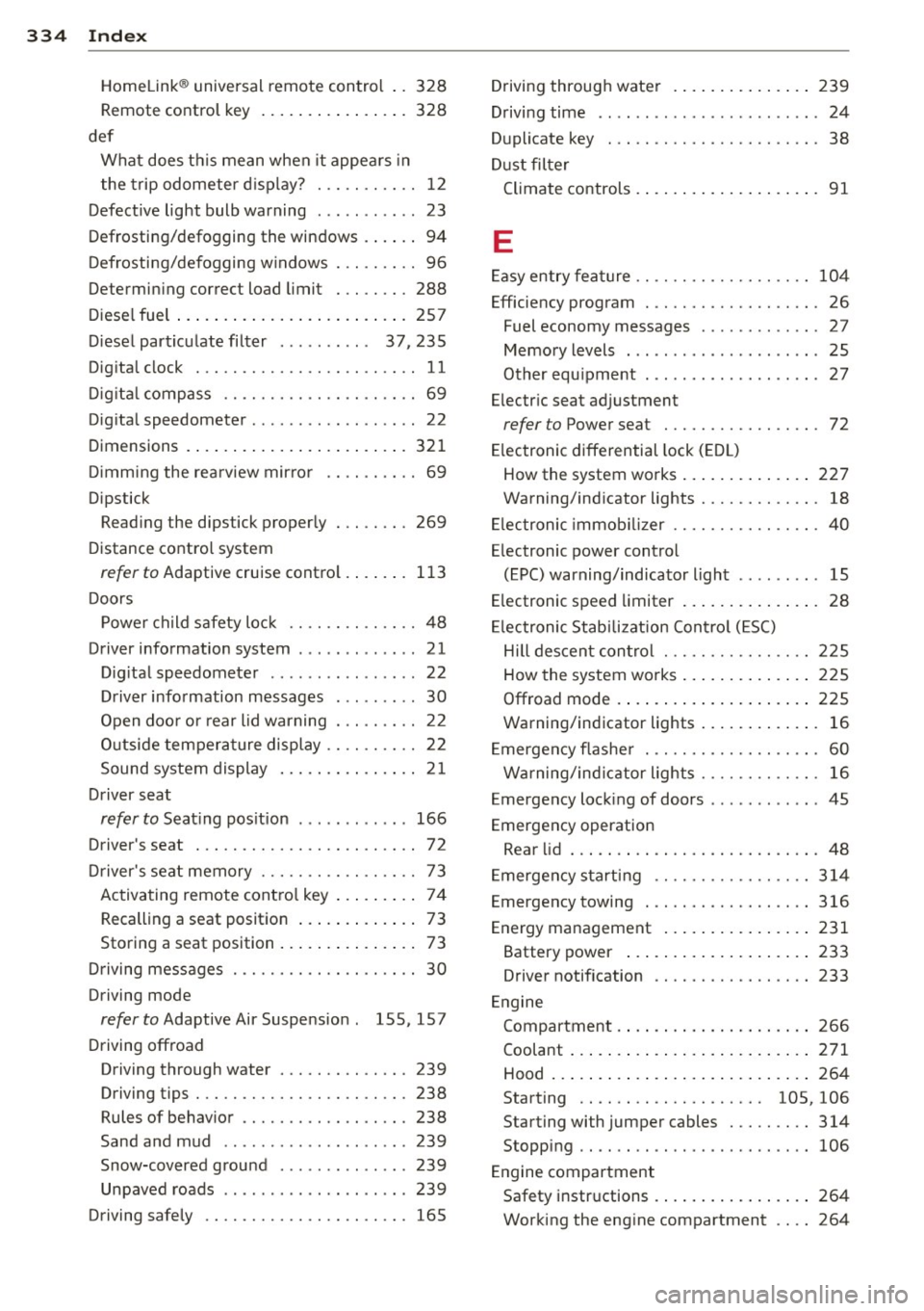
334 Index
------------------------------------
Homelink® universal remote control .. 328
Remote control key ................ 328
def What does this mean when it appea rs in
the trip odometer display? ... .. .... .. 12
Defective light bulb warning . . . . . . . . . . . 23
Defrosting/defogging the windows . . . . . . 94
Defrosting/defogging windows . .. ...... 96
Determining correct load limit . .. .... . 288
Diesel fuel ... ................ ..... . 257
Diesel particulate filter . . . . . . . . . . 37,235
Digital clock . . . . . . . . . . . . . . . . . . . . . . . . 11
Digital compass ......... .. .. .. .. .. .. 69
Digital speedometer ............ .. ... . 22
Dimensions ................ ... .... . 321
Dimming the rearview mirror .. .. ...... 69
Dipstick Reading the dipstick properly . .. .. .. . 269
Distance control system
refer to Adaptive cruise contro l .... ... 113
Doors Power child safety lock .... .. .. .. .. . . 48
Driver information system . .. .. .. .. .. .. 21
Dig ital speedometer ...... .. .. .. .. . . 22
Driver information messages . . . . . . . . . 30
Open door or rear lid warning . . . . . . . . . 22
Outside temperature display .. .. ...... 22
Sound system display ....... .. .... .. 21
Driver seat
refer to Seat ing pos ition ....... .. ... 166
Driver's seat . . . . . . . . . . . . . . . . . . . . . . . . 72
Driver's seat memory ....... .. .. .. .. . . 73
Activating remote control key ..... .. .. 74
Recalling a seat position . . . . . . . . . . . . . 73
Storing a seat position . . . . . . . . . . . . . . . 73
Driving messages . . . . . . . . . . . . . . . . . . . . 30
Driving mode
refer to Adaptive Air Suspension . lSS, 157
Driving offroad
Driving through water ..... .... .... . 239
Driving tips .............. .. .. .. .. . 238
Rules of behavior ........... .. .... . 238
Sand and mud .. ...... .... ... .. .. . 239
Snow-covered ground ...... ..... .. . 239
Unpaved roads ............... .. ... 239
Driving safely ............. .... .... . 165 Driving
through water ........... .. .. 239
Driving time . . . . . . . . . . . . . . . . . . . . . . . . 24
Duplicate key . .. .. ... .......... .. .. . 38
Dust filter
Climate controls . ................. .. 91
E
Easy entry feature .. .. ........... .. .. 104
Efficiency program . . . . . . . . . . . . . . . . . . . 26
Fuel economy messages . . . . . . . . . . . . . 27
Memory levels . . . . . . . . . . . . . . . . . . . . . 25
Other equipment ..... .... ..... .. .. . 27
Electric seat adjustment
refer to Power seat . . . . . . . . . . . . . . . . . 72
Electronic differential lock (EDL)
How the system works .............. 227
Warning/indicator lights ........ .. .. . 18
Electronic immob ilizer ........... .... . 40
Electronic power control (EPC) warning/indicator light . . . . . . . . . 15
E lectronic speed limiter ............... 28
Electronic Stabilization Control (ESC)
Hill descent control . ........... .. .. 225
How the system works .............. 225
Offroad mode .... ............. .... 225
Warning/indicator lights ............. 16
Emergency flasher . . . . . . . . . . . . . . . . . . . 60
Warning/ind icator lights ........ .... . 16
Emergency locking of doors ....... .. .. . 45
Emergency operation Rear lid ....... .. .. .............. .. 48
Emergency starting ................. 314
Emergency towing ... .... .... ... .. .. 316
Energy management ................ 231
Battery power ... ............. .... 233
Driver notification ............. .. .. 233
Engine Compartment .... ................ . 266
Coolant ....... .. .. .............. . 271
Hood ......... .. .. .............. . 264
Starting . . . . . . . . . . . . . . . . . . . . 105, 106
Starting with jumper cables ..... .... 314
Stopping .. .... .. ................. 106
Engine compartment
Safety instructions ................ . 264
Working the eng ine compartment .... 264
Page 340 of 348
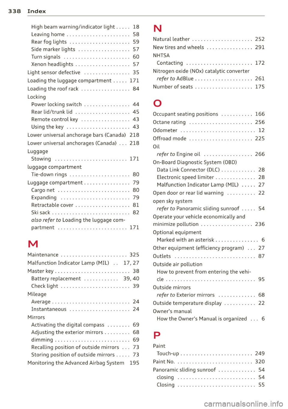
338 Index
High beam warning/indicator light ... .. 18
Leaving home . . . . . . . . . . . . . . . . . . . . . . 58
Rear fog lights . . . . . . . . . . . . . . . . . . . . . 59
Side marker lights ........ .. .. ...... 57
Turn signals .. ........... .... .... .. 60
Xenon headlights .......... ... .. ... . 57
Light sensor defective ....... ... .... . . 35
L oading the luggage compartment ..... 171
Loading the roof rack . . . . . . . . . . . . . . . . . 84
L ocking
Power locking switch . . . . . . . . . . . . . . . . 44
Rear lid/trunk lid .......... ... .... .. 45
Remote control key . . . . . . . . . . . . . . . . . 43
Using the key . ........... .... .... .. 43
L ower universal anchorage bars (Canada) 218
Lower universal anchorages (Canada) 218
Luggage Stowing . ............... .. .. .. .. . 171
l uggage compartment
Tie-down rings ............ ... .... .. 80
Luggage compartment ....... ..... .. .. 79
Cargo net . . . . . . . . . . . . . . . . . . . . . . . . . 80
E xpanding . . . . . . . . . . . . . . . . . . . . . . . . 79
Retractable cover ......... .. .. .. .. .. 81
Ski sack .................... ..... .. 82
also refer to Loading the luggage com-
partment .. ................ ..... . 171
M
Maintenance ................. ..... . 325
Malfunction Indicator Lamp (MIL) . . 17, 27
Master key . . . . . . . . . . . . . . . . . . . . . . . . . . 38
Battery replacement . . . . . . . . . . . . 39, 40
Check light . . . . . . . . . . . . . . . . . . . . . . . . 39
Mileage Average .... ................ ..... .. 24
Instantaneous . . . . . . . . . . . . . . . . . . . . . 24
Mirrors Activating the digital compass . ..... .. 69
Adjusting the exterior mirrors .... ... .. 68
dimming ... ................ ..... .. 69
Recalling position of outside mirrors ... 73
Storing position of outside mirrors . . . . . 73
Monitoring the Advanced Airbag System 195
N
Natural leather .... ............. .... 252
New tires and wheels ...... ...... .. .. 291
NHTSA Contacting .... .. ... .......... .. .. 172
N itrogen oxide (NOx) catalyt ic converter
refer to Ad Blue ... ................ . 261
Number of seats . .. .......... ... .. .. 175
0
Occupant seating positions 166
Octane rating ..... ................ . 256
Odometer . . . . . . . . . . . . . . . . . . . . . . . . . . 12
Offroad mode ... .. ... .......... .... 225
Oil
refer to Engine oil ................ . 266
On-Board Diagnostic System (OBD)
Data Link Connector (DLC) ....... .. .. . 28
Electronic speed limiter ....... .. .. .. . 28
Malfunction Indicator Lamp (MIL) . ... . 27
Open door or rear lid warning .......... 22
open sky system
refer to Panoramic sliding sunroof .... . 54
Operate your vehicle economically and
minimize pollution ................. . 236
Optional equipment Marked with an asterisk . . . . . . . . . . . . . . . 6
Other equipment (efficiency program) .. . 27
Outlets .... .. .. .. ... .......... .... . 87
Outs ide air pollution
How to prevent from entering the vehi-
cle ..... .. .. .. .. ............... ... 95
Outside mirrors
refer to Exterior mirrors . . . . . . . . . . . . . 68
Outside temperature display . . . . . . . . . . . 22
Owner's manual How the Owner's Manual is organ ized . .. 6
p
Pa int
Touch-up .. ....................... 249
Paint No .. .. ....................... 320
Panoramic sliding sunroof . . . . . . . . . . . . . 54
closing ........................... 54
Closing ....... .. ............. ..... 55