AUDI R8 SPYDER 2014 Owner's Manual
Manufacturer: AUDI, Model Year: 2014, Model line: R8 SPYDER, Model: AUDI R8 SPYDER 2014Pages: 244, PDF Size: 61.06 MB
Page 21 of 244
Instrument s and warnin g/indic ator ligh ts 19
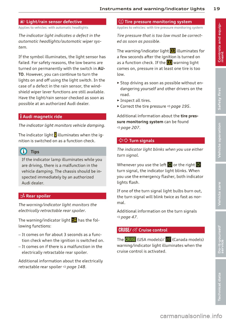
@:> Light/rain sensor defective
Applies to vehicles: with a utomat ic head lights
The indicator light indicates a defect in the
automatic headlights/automatic wiper sys
tem.
If the symbol illuminates, the light sensor has
failed. For safety reasons, the low beams are
turned on permanently with the switch in
A U
TO . However, you can continue to turn the
lights on and off using the light switch . In the
case of a defect in the rain sensor, the w ind
shie ld wiper lever functions are sti ll available.
Have the light/rain sensor checked as soon as
possible at an authorized Audi dealer.
; Audi magnetic ride
The indicator light monitors vehicle damping .
The indicator l ight
B illum inates when the ig
n ition is switched on as a f unct ion check.
@ Tips
If the ind icator lamp illum inates while you
are driving, there is a malfunct ion in the
veh icle damping. The chass is should be in
spected immediately by an authorized
Audi dea ler .
-::}. Rear spoiler
The warning/indicator light monitors the
electrically retractable rear spoiler.
The warning/ind icator ligh t
IJ has the fol
l owing f unctions:
- It comes on for about 3 seconds as a func
t ion check when the ignition is sw itched on.
- It comes on if there is a malfunction in the
electrically retractable rear spoiler.
Addit ional information about the electrically
retractable rear spoi ler
c> page 148.
ill Tire pressure monitoring system
Applies to vehicles : wit h tire press ure mo nitor ing system
Tire pressure that is too low must be correct
ed as soon as possible.
The warning/indicator lig ht
RE illuminates for
a few seconds after the ignition is turned on
as a function check. If the
RE warning light
comes on, pressure in at least one tire is too
l ow .
.,. Stop driving as soon as possible w ithout en
dangering yourself and other drivers on the
road.
.,. Inspect all tires .
.,. Correct t he tire pressure
c> page 195.
Additional informat ion about the
tire pr es
s ur e monit oring system
can be found
c> page 207.
¢ ¢Turn signals
The indicator light blinks when you use either
turn signal.
Whenever you use the left
B or the right B
turn s ignal, the indicator light blinks . Whe n
you use the emergency flashe r, both indicator
lights flash.
If one of the turn signa l light bulbs bu rn out,
the turn signal w ill blink twice as fast as nor
mal.
Additional informat ion on the turn s ignals
c> page47 .
CRUISE/ c,)"' Cruise control
The tB;m~14 (U SA mode ls)/ • (Canada models)
warning/indicator light illuminates when the
c ruise control is activa ted.
Page 22 of 244
20 Driver information system
Driver information
system
Introduction
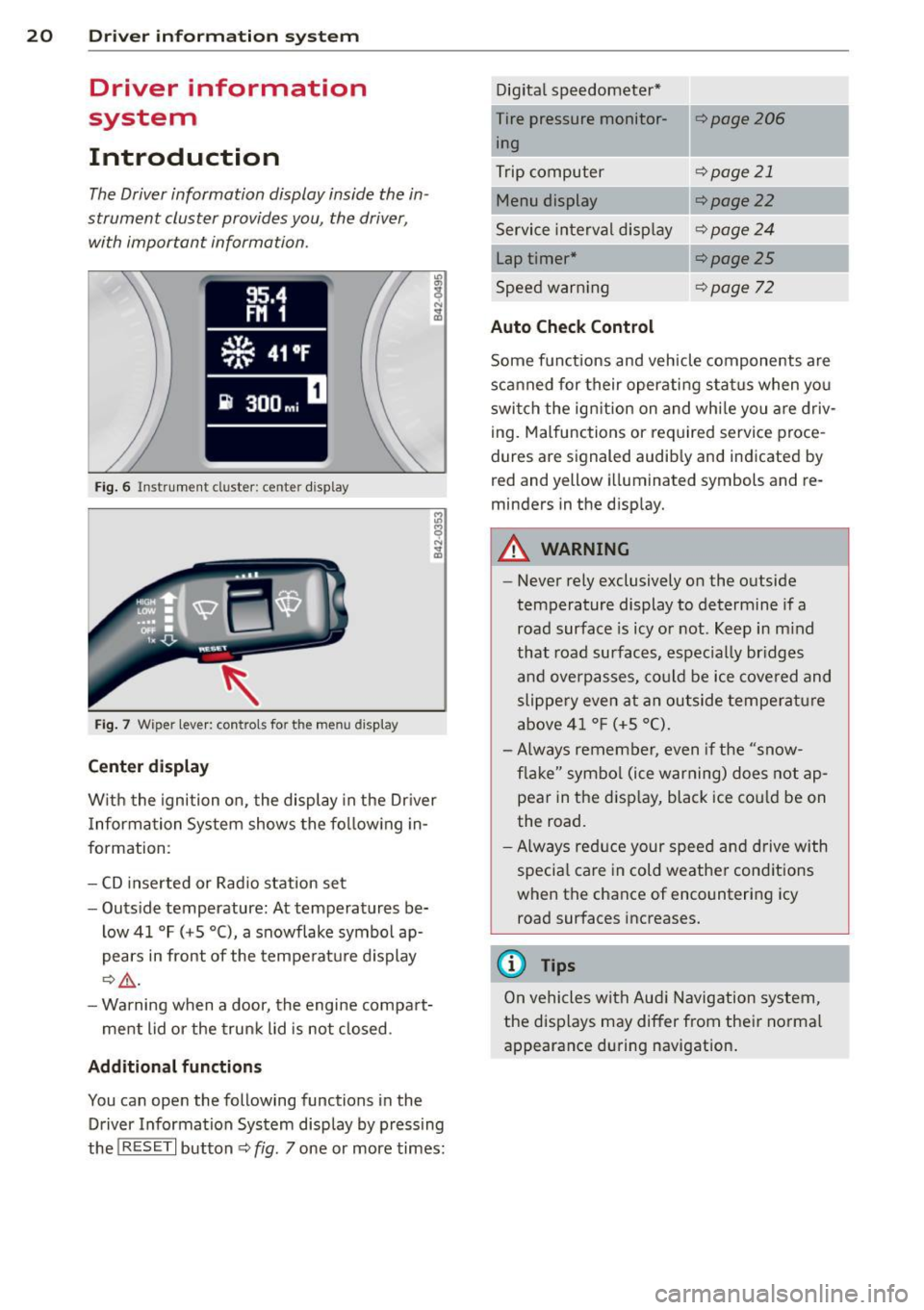
The Driver information display inside the in
strument cluster provides you, the driver ,
with important information.
Fig. 6 In strum en t cl ust er: center display
Fig. 7 W iper le ver: c on trols fo r the menu disp lay
Center display
W ith the ignition on, the display in the Dr iver
I nformation System shows the following in
formation :
- CD inserted or Radio station set
- Outside temperature: At temperatures be-
low 41 °F ( +S °C), a snowflake symbol ap
pears in front of the temperature display
¢.&_ .
-Warning when a door, the engine compart-
ment lid or the trunk lid is not closed .
Additional functions
You can open the following function s in the
Driver Information System disp lay by pressing
the
! R ESE T I button ¢ fig. 7 one or more times: Digital
speedometer*
Tire pressure monitor ing
Trip computer
Menu display
Service interval display
Lap timer*
Speed warn ing
Auto Check Control
¢page206
¢page 21
¢ page22
¢page24
¢page25
¢page 72
Some functions and vehicle components are
scanned for their operating status when you
switch the ign ition on and whi le you are driv
ing. Malfunctions or required service proce
dures are signaled audib ly and indicated by
red and y ellow illuminated symbols and re
m inders in the display.
A WARNING
--
- Never rely exclusively on the outside
temperature display to determine if a
road surface is icy or not . Keep in mind
that road surfaces, espec ially br idges
and overpasses, could be ice covered and
slippery even at an outside temperature
above 41 °F (+S °C).
- Always remember, even if the "snow
flake" symbol (ice warning) does not ap
pear in the display, black ice cou ld be on
the road.
-Always reduce your speed and drive with
specia l care in cold weather conditions
when the chance of encountering icy road surfaces increases.
@ Tips
On vehicles with Aud i Navigation system,
the displays may differ from their normal
appearance during navigation.
Page 23 of 244
Trip computer
Introduction
The trip computer gives you information on
current and average fuel mileage, average
speed, fuel range and driving time .
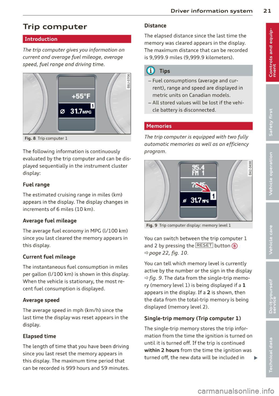
Fig. 8 T rip comp ute r 1
The fo llow ing informa tion is cont inuo usly
eva luated by the trip compu ter and can be dis
p layed sequentia lly in the instrument cl uster
d isplay:
Fuel range
The estimated c ruising ra nge in miles (km)
appears in the d isplay . The disp lay changes in
increments of 6 miles (10 km) .
Average fuel mileage
The average fue l economy in MPG (l/ 100 km)
since you last clea red the memory appears in
t his display .
Current fuel mileage
The instantaneous fuel consumption in miles
pe r gallon (l/ 100 km) is shown in this d isp lay .
When the ve hicle is stationary, the most re
cent fuel consumpt io n is displayed.
Average speed
The average speed in mph (km/h) since the
last time the display was reset appears i n the
d isp lay.
Elap sed t ime
The length of time that you have been driving
since you las t reset the memory appears in
this display . The maximum t ime period that
can be recorded is 999 ho urs and 59 minutes .
Driver in formation system 21
Distance
The elapsed dis tance sin ce the las t time the
memory was cleared appears in the d isp lay .
T he maxim um distance that can be recorded
is 9 ,999.9 miles (9,999 .9 k ilometers) .
(D Tips
- Fuel consump tions (average and cur
rent), range and speed are disp layed in
metric un its on Canadian mode ls.
- All sto red val ues wil l be lost if t he vehi
cle battery is d isconnected .
' . Memories
The trip computer is equipped with two fully
automatic memories as well as on efficiency
progrom.
Fi g. 9 Trip co mputer d isplay: memo ry level 1
You can switch between the trip computer 1
and 2 by pressing the
I R ESET I but ton ®
qpage 22, fig . 10 .
You can tell wh ich memory leve l is currently
active by the number or the sign in the display
Q fig . 9. The data from the single-trip memo
ry (memo ry level 1) is being displayed if a
1
appea rs i n t he display . If a 2 is shown, then
the data from the total- trip memory is being
displayed (memory level 2).
Single-trip memory (Trip computer 1)
T he sing le-trip memory stores the tr ip i nfo r
mation from the time the ign it ion is tu rned on
u nt il i t i s tu rn ed off .
If the trip is cont inued
with in 2 h ours from t he time the ignition w as
tu rned off, the new data will be in cl ud ed in .,..
Page 24 of 244
22 Driver information system
the calculation of the current trip informa
t ion. If the trip is interrupted for
more than 2
hours
the memory is reset automatica lly.
Total-trip memory (Trip computer 2)
Unlike the sing le-trip memory, the total-trip
memory is not reset automatically. This per
mits you to evaluate your driving data for the
entire period between manual resets.
Operation
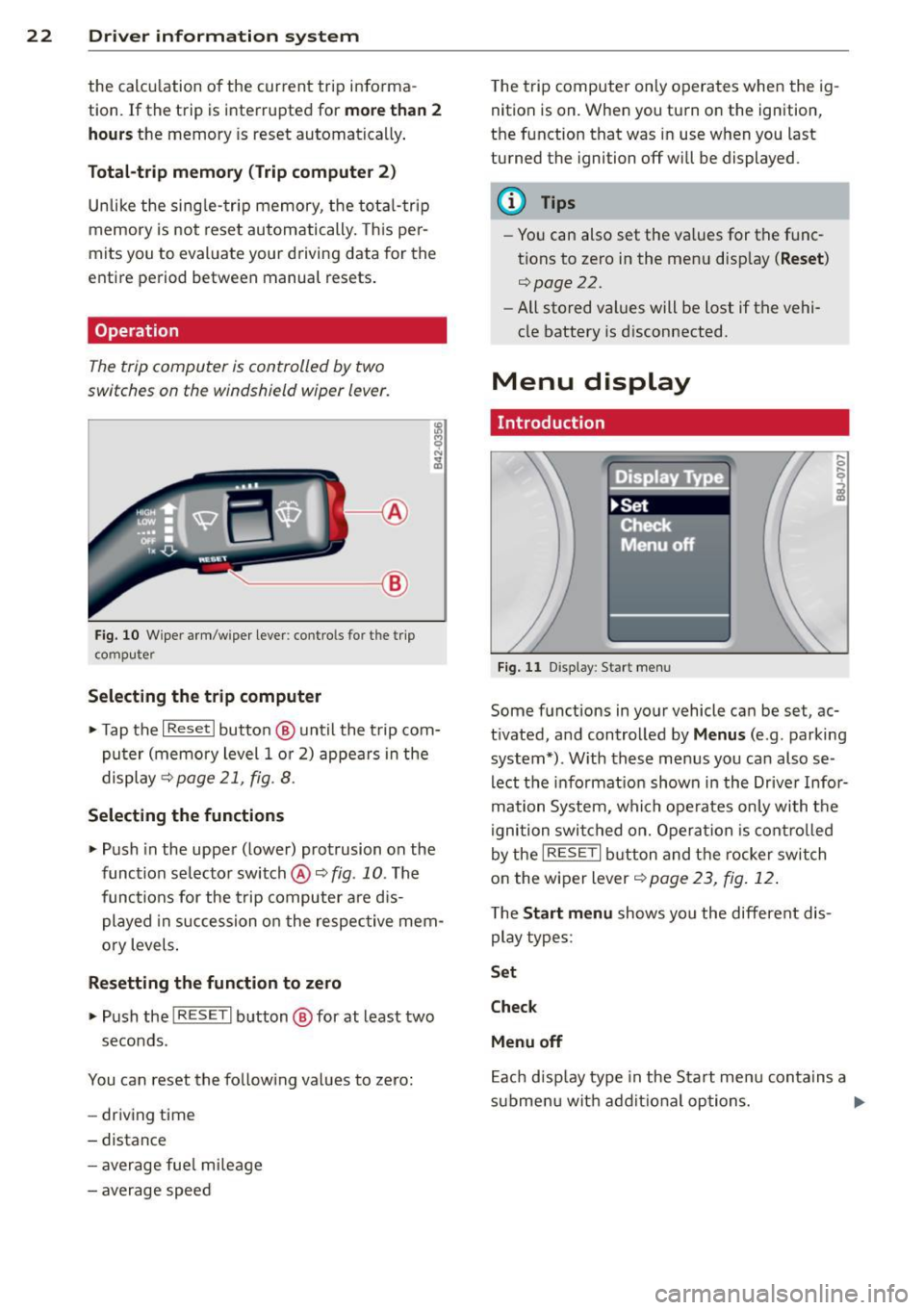
The trip computer is controlled by two
switches on the windshield wiper lever.
'----- ®
Fig. 10 W iper arm /wiper lever: contro ls fo r the trip
co mp ute r
Selecting the trip computer
.. Tap the I Reset I button @ until the trip com
puter (memory level 1 or 2) appears in the
display ~page21 ,
fig. 8.
Selecting the functions
.. Push in the uppe r (lower) protrusion on the
function se lector switch @¢
fig. 10 . The
functions for the trip computer are dis
played in succession on the respective mem
ory levels .
Resetting the function to zero
.. Push the I RESE T I button @ for at least two
seconds.
You can reset the follow ing values to zero:
- driving time
- distance
- average fue l m ileage
- average speed T
he trip computer only operates when the ig
nition is on. When you turn on the ignition,
the function that was in use when you last
turned the ignition off will be displayed .
@ Tips
-Yo u can also set the va lues for the func
tions to zero in the menu disp lay
( Reset )
r:::>page 22.
- All stored values will be lost if the vehi
cle battery is d isconnected.
Menu display
. Introduction
Fig . 11 D isp lay: Start menu
Some f unctions in yo ur vehicle can be se t, ac
tivated, and controlled by
Menus (e .g . parking
system*) . With these menus you ca n also se
lect the informat ion shown in the Driver Infor
mation System, which operates only with the
ignition switched on. Operation is controlled
by the
IRESE TI button and the rocker switch
on the wiper lever
r:::> page 23 , fig. 12 .
The Start menu shows you the different dis
play types :
Set
Check
Menu off
Each display type in the Start menu contains a
s ub menu wit h additional options. ..,_
Page 25 of 244

Set Clock¢ page 24
Tire pressure ¢page206
Computer
c::> page 2 4
Speed warning
c::> page 73
Langu age
c::> page 24
Units (distance, fuel consump-
tion, temperature)
c::> page 24
Lap timer
c::> page 25
Lights
c::> page 46
Wiper (service posit ion)
c::> page 53
Doors (unlocking and locking
mode, for e xample Auto-lock)
c::> page 30, c::> page 30
Check Service c::> page 24
Chassis number
c::> page 223
Keys
Menu off The menu display is hidden and
. the lap timer appears .
Navigating the menu
Use the rocker switch on the windshield wiper
lever and the
I RESET I button to ope rote the
menu and carry out inquiries and selections.
~-- @
Fig. 12 W iper leve r: Co ntrols for the menu d isplay
F ig . 13 D isplay: Start menu
Driver in formation system 23
I Reset I button @ and rocker switch @
c::> fig. 12 fu nctions:
To open the menu
~ Press the I Reset I but to n @ unti l the me nu
disp lay
c::> fig . 13 appears
Selections and settings
~ Press the rocker switch @to reac h a menu
display. The switch is operated the same as
th e display (up/down) .
Entering and confirming
~ Press the I RESET I button @.
Returning to the Start menu
~ Press the I RESET I button longer than 2 sec
onds to return from any menu level to the
Start menu .
U sing the rocker swi tc h, you can selec t the
men us in the display or change settings. A
cu rsor appea rs on the left in front of th e se
lected values.
By press ing the
! RESET I button, you act ivate
the se lec tion you made or confirm the va lues
yo u set.
Sele cted functions are identified wit h
a check mark or are carried out directly .
Mean ings of the symbols i n the display:
Selec
tion bar
>
./
D
Selected funct io n Mea ning
Cursor
C heck ma rk
Box Curren
t Selec
tion
Selected or
Function active
Not selected
Tr ian gle pointi ng Previou s page
up
Triangle pointing IINext page
down
Page 26 of 244
24 Driver information system
Selecting settings
The Driver Information System settings are
menu-guided .
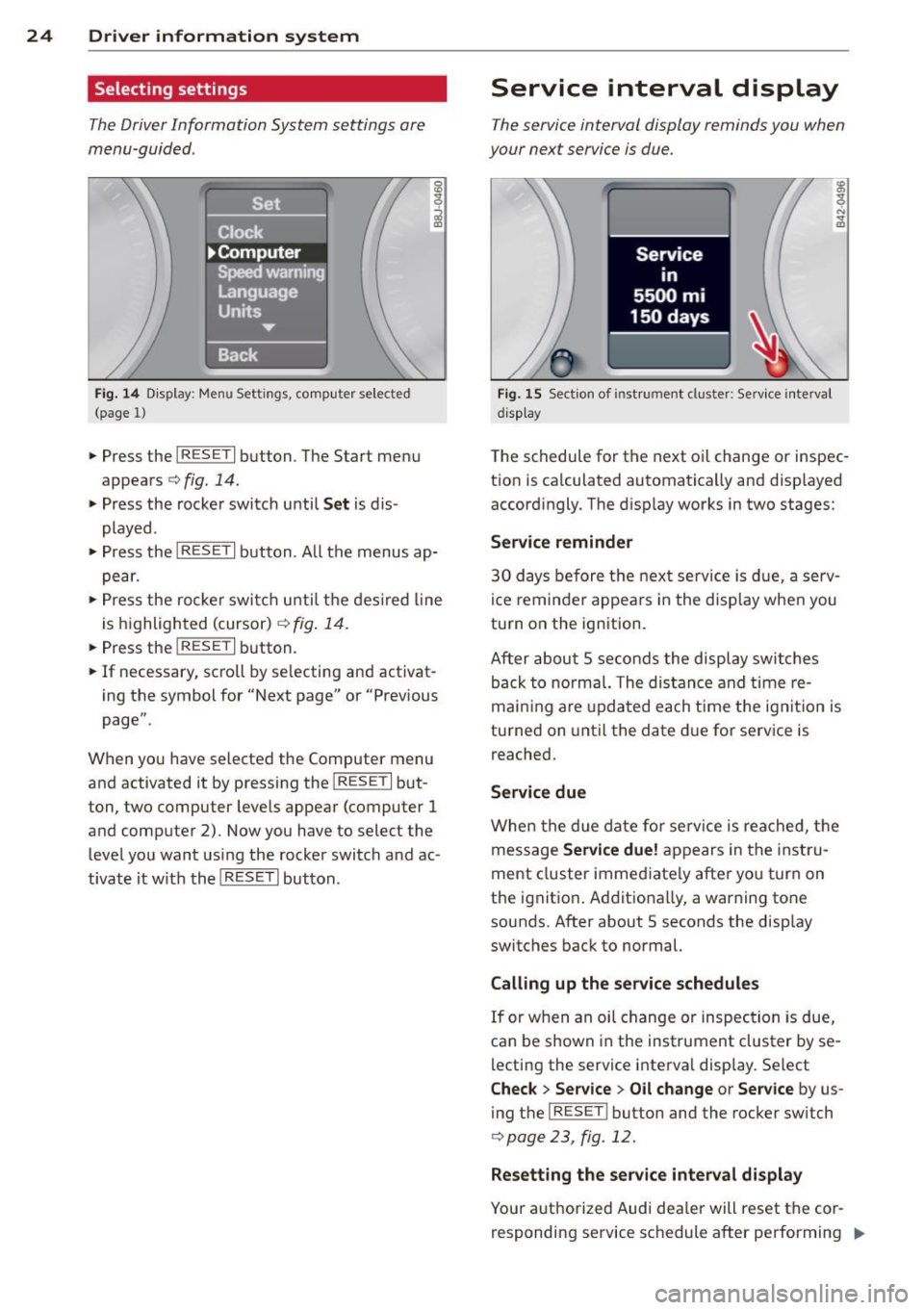
Fig. 14 Display: Menu Settings, comp uter selected
(page 1)
• Press the I RESET I button. The Start menu
appears
c:> fig. 14.
• Press the rocker switch until Set is dis
played .
• Press the
I RESE T I button . A ll the menus ap
pear.
• Press the rocke r swi tch until the desired line
is highlighted (cursor)
c:> fig. 14.
• Press the I RESET I button.
• If necessary, scroll by se lecting and activat
ing the symbol for "Next page" or "Previous
page".
When you have selected the Computer menu
and activated it by pressing the
I RESET I but
ton, two computer levels appear (computer
1
and computer 2). Now you have to select the
level you want using the rocker switch and ac
tivate it w ith the
I RESET I button.
Service interval display
The service interval display reminds you when
your next service is due.
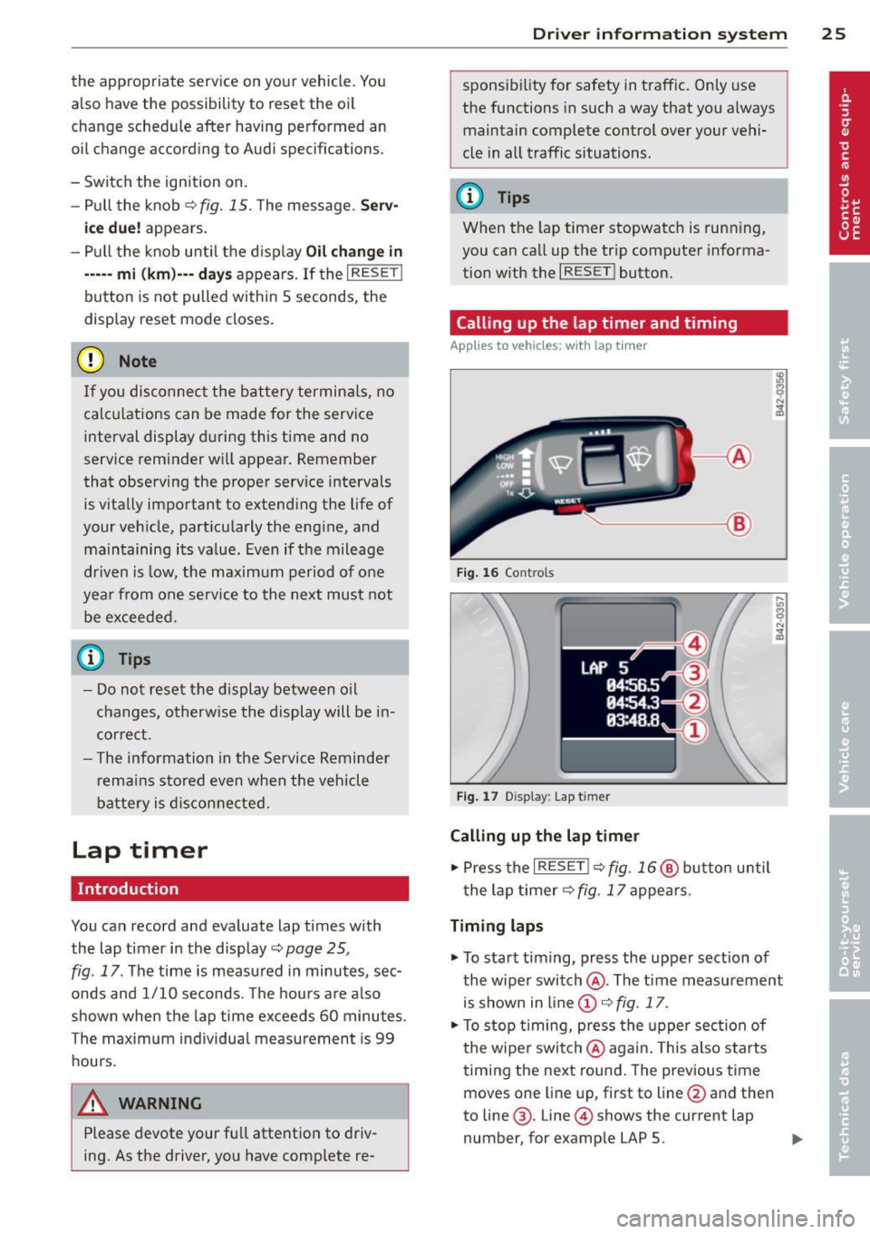
Fig. 15 Section of ins tru ment cl uster: Service interval
d isplay
The schedule for the next oi l change or inspec
tion is ca lculated automatically and displayed
accordingly. The disp lay works in two stages:
Service reminder
30 days before the next service is due, a serv
ice reminder appears in the display when you
turn on the ignition.
After about
5 seconds the display switches
back to normal. The distance and time re
maining are updated each time the ignition is
turned on until the date due for service is
reached.
Service due
When the due date for service is reached, the
message
Service due! appears in the instru
ment cluster immed iate ly after you turn on
the ignit ion . Additionally, a warning tone
sounds. After about 5 seconds the display
switches back to normal.
Calling up the service schedules
If or when an oil change or inspection is due,
can be shown in the instrument cluster by se
lecting the service interva l display. Select
Check > Service > Oil change or Service by us
ing the
I RES ET I bu tton and the rocker switch
c:> page 23, fig. 12.
Resetting the service interval display
Your authorized Audi dea ler will reset the cor
responding service schedule after performing .,.
Page 27 of 244
the appropriate service on yo ur vehicle. You
also have the possibility to reset the oi l
change sched ule after having performed an
oil change according to Audi specifications.
- Swi tch the ign ition on.
- Pull the knob ~fig.
15. The message. Serv-
ice due! appears.
- Pull the knob until the d isplay
Oil change in
---- -mi (km)---
d ays appears . If the I RESET !
button is not pulled within 5 seconds, the
display reset mode closes.
(D Note
If you disconnec t the bat tery termin als, no
calc ulations can be made for the service
interval display during this t ime and no
service reminder w ill appear. Remember
that observing the proper serv ice intervals
is vitally impo rtant to extending the life of
your veh icle, part icu larly the eng ine, and
ma intaining its va lue . Even if t he mileage
driven is low, the maximum per iod of one
yea r from one se rvice to the next must not
be excee ded .
0) Tips
- Do not reset the display between o il
c hanges, o therw ise the display will be in
cor rect.
- The information in the Service Reminder
r ema ins s to red even when the veh icle
batte ry is dis con ne cte d.
Lap timer
Introduction
You can record and eva luate lap times with
the lap t imer in the display~
page 25,
fig . 17 . The time is measu red in minutes, sec
onds and 1/10 seconds . Th e hours a re a lso
shown when the lap time exceeds 60 mi nutes.
The maximum individual measu rement is 99
hours.
_& WARNING
Please devote your fu ll attention to driv
ing. As the driver, you have comp lete re -
Driver in formation system 25
sponsibi lity for safety in traff ic. On ly use
the functions in such a way that you a lways
maintain complete control over your vehi
cle in all traffic situations.
(D Tips
When the lap timer stopwatch is running,
you can ca ll up the tr ip comp uter informa
tion with the
I RESET ! button.
Calling up the lap timer and timing
Applies to vehicles: with lap tim er
~-- @
Fig. 16 Co ntro ls
F ig . 1 7 Display : Lap t imer
Calling up the lap timer
.. Press the I RESET !~ fig. 16@ butto n until
t he lap timer~ fig.
17 appears.
Timing laps
.. To start timing, press the upper section of
the wiper swi tch @ . The tim e measurement
is shown in line @ ~ fig.
17 .
.. To stop t iming, press the upper sec tion of
t he wipe r switch @aga in. This also s tarts
t iming the ne xt round . The previous time
moves one line up, first to line @and the n
to line @. Line @ shows the current lap
number, for example LAP 5. .,.
Page 28 of 244
26 Driver information system
Displaying intermediate time and pausing
timing
• To display an intermediate time, press the
l ower section of the w iper switch @. T he in
termediate time appears in line
CD and is
marked with*.
• To pause tim ing, press the lower section of
the wiper switch @again.
• To continue timing, press the upper section
of the w iper switch @.
If t iming is paused, you can conti nue it later
even if you switch the ign it ion off.
Evaluating times and continuing or
resetting timing
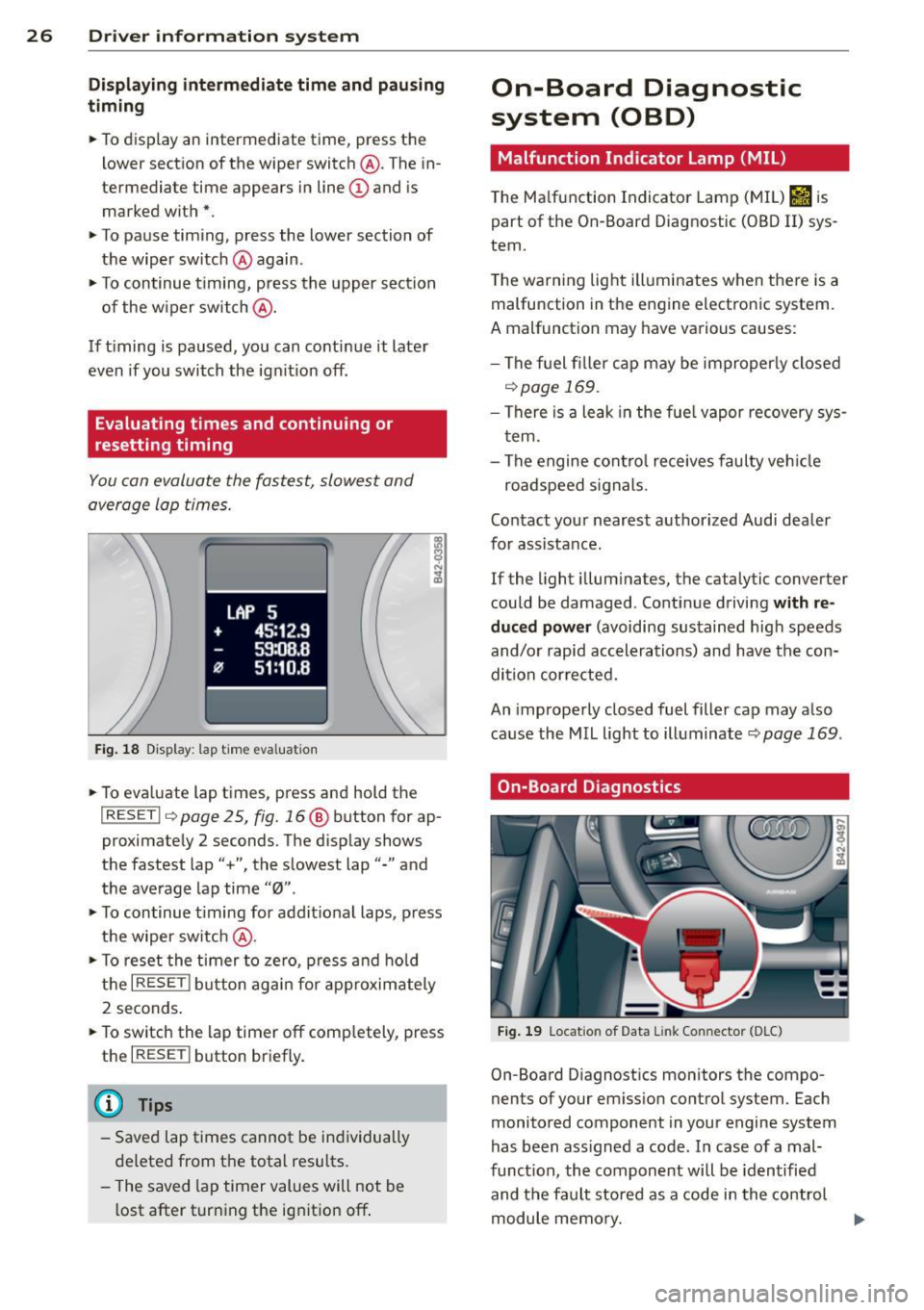
You can evaluate the fastest, slowest and
average lap times.
Fig. 18 Display : lap time eva luation
• To eva luate lap times, press and hold the
I RESET I 9 page 2 5, fig. 16 @ button for ap
proximate ly 2 seconds. The display shows
the fastest lap"+", the s lowest lap"-" and
the average lap time
"0" .
• To continue t iming for addit ional laps , press
the wiper switch @.
• To reset the timer to zero, press and hold
the
I RESE T! button again for approximately
2 seconds .
• To switch the lap timer off comp letely, press
the
I RESET ! button briefly.
(D Tips
-Saved lap times cannot be individually
deleted from the total results.
- The saved lap timer values will not be
l ost after turning the ignition off .
On-Board Diagnostic
system (OBD)
Malfunction Indicator Lamp (MIL)
The Ma lfunction Indicator Lamp (MIL) &iJ is
part of the On -Board Diagnostic (OBO II) sys
tem.
T he wa rning light ill uminates when the re is a
malfunction in the engine electronic system.
A malfunction may have various causes :
- The f uel filler cap may be improperly closed
,=;,page 169.
-There is a leak in the fuel vapor recovery sys
tem.
- The engine control receives faulty vehicle
roadspeed signals.
Contact your nearest authorized Audi dealer
for assistance.
If the light illuminates, the catalytic converter
could be damaged . Continue driving
with re
duced power
(avoiding sustained high speeds
and/or rapid accelerations) and have the con
di tion cor rected.
An improperly closed fuel filler cap may also
cause the MIL light to illuminate
r=;, page 169 .
On-Board Diagnostics
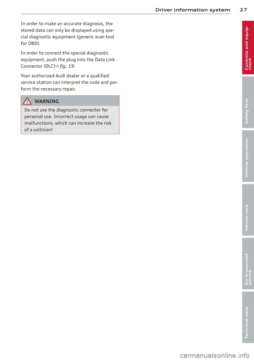
Fig. 19 Locat io n of Data Li nk Conn ecto r (D LC)
On-Board D iagnostics monitors the compo
nen ts of your emission control system . Each
monitored component in your engine system
has been ass igned a code . In case of a mal
funct ion, the component will be identified
and the fault stored as a code in the control
module memory.
Page 29 of 244
In o rder to make an accurate diagnosis, the
stored data can only be displayed using spe
cial diagnostic equipment (gener ic scan tool
for OBD).
I n o rder to connect the special diagnostic
equipment, push the plug into the Data Link
Connector (DLC)¢
fig. 19.
Your authorized A udi dealer or a qualified
service station can interpret the code and per
form the necessary repair.
A WARNING
Do not use the diagnostic connector for
personal use. Incorrect usage can cause
ma lfunctions, which can increase the risk
of a coll is ion!
-
Driver information system 2 7
Page 30 of 244
28 Opening and closing
Opening and closing
Keys
Key set
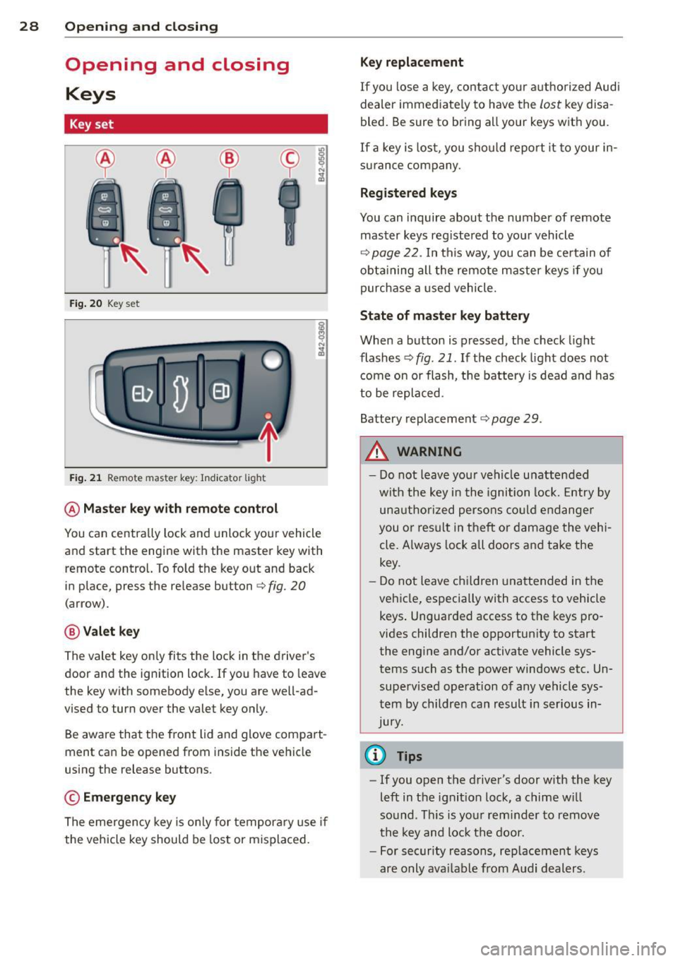
Fig. 20 Key set
Fig. 21 Remot e mas ter key : Indicator ligh t
@ Master key with remote control
You can centrally lock and unlock your vehicle
and start the engine with the master key with
remote control. To fold the key out and back
in place, press the re lease button
c:> fig. 20
( a rrow).
@ Valet key
The valet key on ly fits the lock in the driver's
door and the ignition lock . If you have to leave
the key with somebody e lse, you are well-ad
vi sed to tu rn over the valet key only.
Be aware that the front lid and glove compart
ment can be opened from inside the vehicle
using the release buttons .
© Emergency key
The emergency key is only for temporary use if
the vehicle key should be lost or misplaced.
Key replacement
If you lose a key, contact your authorized Audi
dealer immed iate ly to have the
Lost key disa
bled. Be sure to bring all your keys with you .
If a key is lost, you should report it to your in
surance company .
Registered keys
You can inquire about the number of remote
master keys registered to your vehicle
c:> page 22 . In this way , you can be certain of
obtaining all the remote master keys if you
purchase a used vehicle.
State of master key battery
When a button is pressed, the check light
flashes
c:> fig . 21 . If the check light does not
come on or flash, the battery is dead and has
to be replaced.
Battery replacement
c:::;, page 29 .
.&_ WARNING ~
- Do not leave your vehicle unattended
with the key in the ignition lock. Entry by
unauthorized persons could endanger
you or result in t heft or damage the vehi
cle. A lways lock all doors and take the
key.
- Do not leave children unattended in the
vehicle, especially with access to vehicle keys . Unguarded access to the keys pro
vides children the opportunity to start the engine and/or activate vehicle sys
tems such as the power windows etc. Un supervised operation of any vehicle sys
tem by children can result in serious in
Jury.
{l) Tips
- If you open the driver's door with the key
left in the ignit ion lock, a chime will
so und . This is your reminder to remove
the key and lock the door.
- For security reasons, replacement keys
are only available from Audi dealers.