key AUDI S6 2009 Service Manual
[x] Cancel search | Manufacturer: AUDI, Model Year: 2009, Model line: S6, Model: AUDI S6 2009Pages: 398, PDF Size: 43 MB
Page 124 of 398
![AUDI S6 2009 Service Manual -On the road --------------------
[
i] Tips
• You can apply the parking brake at any time - even with the igni
tion turned off. The ignition must be turned on in order AUDI S6 2009 Service Manual -On the road --------------------
[
i] Tips
• You can apply the parking brake at any time - even with the igni
tion turned off. The ignition must be turned on in order](/img/6/57595/w960_57595-123.png)
-On the road --------------------
[
i] Tips
• You can apply the parking brake at any time - even with the igni
tion turned off. The ignition must be turned on in order to release
the parking brake .
• Occasional noises when the parking brake is applied and
released are normal and are not a cause for concern .
• The parking brake goes through a self -test cycle at regular inter
vals - when the vehicle is parked . Any associated noises are
normal. •
Parking
To prevent a parked vehicle from rolling away, there are a
few things you should do.
When you park your vehicle, do the following
- Stop the vehicle using the brake pedal.
- Pull the switch to apply the electromechanical parking
brake.
- Move the selector lever into the
P position ~& .
- Switch off the engine and remove the ignition key from
the ignition lock.
When you park your vehicle on hills, do the
following - Stop the vehicle using the brake pedal.
- Pull the switch to apply the electromechanical parking
brake.
- If you are parking headed downhill, turn the front wheels
toward the curb. - If you are
parking headed uphill, turn the front wheels
awayfrom the curb.
- Move the selector lever into the P position .
- Switch off the engine and remove the ignition key from
the ignition lock.
& WARNING
This is how you can reduce the risk of injury when leaving your
vehicle.
• Never park the vehicle where it can come in contact with dry
grass, spilled fuel or any other flammable materials.
• When parking on hills, always turn the wheels so that the front
wheels will first roll into the curb, if the vehicle should start to roll.
• Never allow anyone -especially small children -to remain in the
vehicle when it is locked. Locked doors make it more difficult for
rescuers to access the passenger compartment in the event of an
emergency. Danger to life!
• Never leave children unsupervised in the vehicle. Children
could release the parking brake or move the gearshift lever out of
gear. The vehicle could start to roll away and cause an accident.
• No matter what the season is, the temperature in a parked
vehicle can reach dangerous levels.
0 Note
• Please exercise care when you park your vehicle in parking areas
with parking barriers or curbs. Parking barriers and curbs vary in height and could damage your bumper and related components as
the front of your vehicle moves over a barrier or curb that is too
high, as you park or as you back out of a parking spot. In order to be
sure that no such damage can occur, you may wish to stop short of
having the front tires of your car touch the parking barrier or curb . ..,_
Page 142 of 398
• ..__A_ d_ a-:.. p_t _iv _ e_ C_r_ u_ i _s _ e_ C_ o_n_ t_ r_ o_ l _____________________________________________ _
Sav ing s etting s
Your individual settings are automa tically saved and assigned to the
remote control key being used {remote key storage). If the key is
given to another person, the saved settings remain as they are. •
System limitations
Applies to vehic les : with Adapt ive Crui se Co ntro l
General information
The radar sensor has limits that the driver must know to
b e able to use AC C properly.
The Adaptive Cruise Control works within limits that are also re lated
to radar sensor range and sight d istance. In some situations ACC
may react unusually or late from the driver's point of view. There
fore, always be attentive to what is happening around you and
a lways be ready to in tervene, if necessary:
• when driving around curves=>
page 140
• whe n vehicles up front are not in line with y our vehicle
=>
page 141
• when other vehicles a re changing lanes => page 141
• when other vehicles are difficu lt to detect => page 141.
• when vehicles up ahead are not moving or obstacles are in your
travel lane=>
page 141
& WARNING
The radar sensor's function and range can be r educed by rain ,
sn ow and he avy spray. Moving vehicles up ahead may not be
promptly det ected or ma y not be det ected at all.
• Alway s pay careful attention to the traffi c situatio n a nd be
ready to intervene and be ready to take complete contr ol when
e ver ne ces sary . •
Ap plies to veh ic les: with Ad apt ive Crui se Contro l
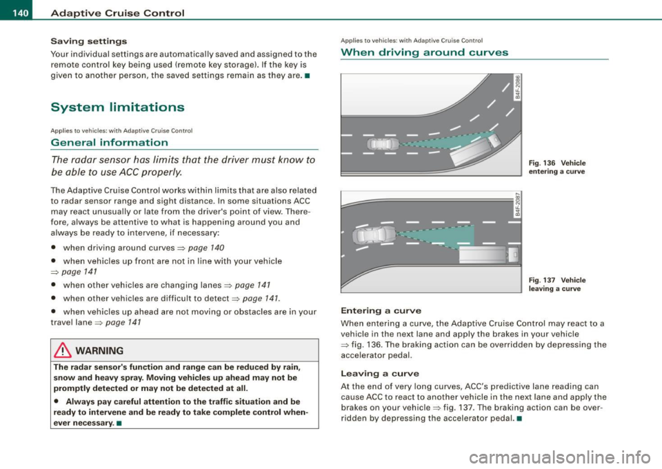
When driving around curves
k::;=========== =,!
~
[J
Ent ering a cur ve
Fi g. 13 6 Veh icle
e nteri ng a curv e
Fig. 137 Ve hicle
l ea ving a curv e
When entering a curve, the Adaptive Cruise Control may react to a
vehicle in the next lane and apply the brakes in your vehicle
=> fig. 136. The braking action can be overridden by depressing the
acce lerator pedal.
Lea vin g a c urve
At the end of very long curves, ACC 's predictive lane reading can
cause ACC to react to another vehicle in the next lane and apply t he
brakes on your vehicle=> fig. 137 . T he braking action can be over
ri dden by depressing t he accelerator peda l.•
Page 147 of 398
___________________________________________________ A_u_ d_i_ l_ a _ n_ e_ a _ s_s _ i_s _t __ lffll
- Sele ct Warning early , adaptive or late ~ page 144,
fig. 145.
Setting th e st eering wheel vibration
- Press the
I CAR I function button.
- Selec t Sy stems ·* in t he CAR me nu.
- Selec t Audi lane a ssis t.
- Selec t Steering vibrat ion weak , medium or strong.
Setting th e warning tim e
Earl y:
This setting warns the driver before a wheel touches the
detected lane boundary line. The warning depends on the vehicle's
angle as it approaches the boundary line . If you approach a
boundary l ine gradua lly, the warning will occur ear lier. If you
approach the boundary line at a very sharp angle, the warning wi ll
occur just before a whee l touches the line.
Adapti ve : In this setting, the warning time adjusts to the character
istics of the road and the vehicle speed. The warning occurs later for
curves and occurs earlier for straight stretches of road . The warning
occurs later on narrow roads than on wide roads.
Late: This setting warns the driver when a whee l drives over the
detected lane boundary line.
Se ttin g th e steering wheel vibrat ion
When adjusting the steering wheel vibration, the steering wheel
v ibrates so that you can check the intensity you have set.
[ i ] Tips
• When making the adjustment, lane assist is not activated . The
steering whee l vibrates briefly only to assist you in changing the
setting .
• Your settings are automatically stored and assigned to the
remote contro l key being used. •
Controls and equip
ment I • •
Page 154 of 398
1111 Audi side assist
--------------------
G) Sig nal o n outs ide mirr or does no t l ight up
If you activate your turn signal in driving situat ion @, the signal sti ll
does not light up on the outside mirror:::::,
& in "Safety tips" on
page 154. •
Applies to vehic les: with side assist
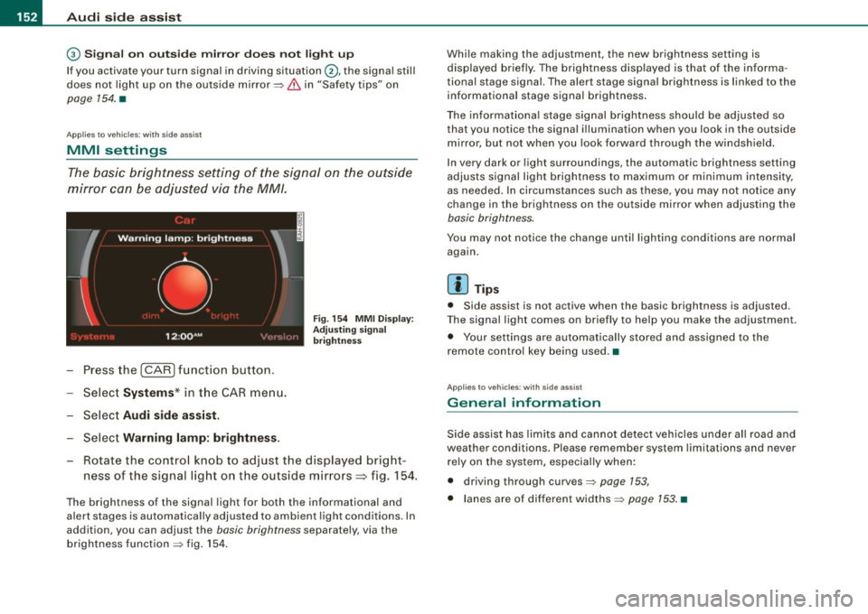
MMI settings
The basic brightness setting of the signal on the outside
mirror can be adjusted via the MM/.
- Press the I CAR I function button.
- Select
Syst ems * in t he CAR menu.
- Selec t
Audi side a ssis t.
Selec t Warning lam p: brightn ess.
Fig. 154 MMI Disp la y:
Adj ust ing s igna l
br ightn ess
Rotate the contro l knob to adjust the displayed bright
ness of the signal light on the outside mirrors~ fig. 154.
The brightness of the signal light for both the informational and
a lert stages is automatica lly adjusted to ambient light cond itions . In
addition, you can adjust the
basic brightness separately, via the
brightness function :::::, fig. 154 . Whi
le making the adjustment, the new brightness setting is
displayed briefly. The brightness disp layed is that of the informa
tiona l stage signal. The alert stage signa l brightness is linked to the
informational stage signal brightness .
The informat iona l stage signal brightness shou ld be adjusted so
that you notice the signal illumination when you look in the outside
m irror, but not when you look forward through the windsh ield .
I n very dark or light surroundings, the automatic brightness setting
adjusts signal light brightness to maximum or minimum intensity,
as needed . In circumstances such as these, you may not notice any
change in the brightness on the outside mirror when adjusting the
basic brightness.
You may not notice the change until lighting conditions are normal
aga in.
[ i ] Tips
• Side assist is not active when the basic brightness is adjusted.
T he signal light comes on briefly to he lp you make the adjustment.
• Your settings are automatically stored and assigned to the
remote contro l key being used .•
Ap plies to vehic les: with side assist
General information
Side assist has lim its and cannot detect vehicles under a ll road and
weather conditions. Please remember system limitations and never
rely on the system, especia lly when:
• driving through curves:::::,
page 153,
• lanes are of different widths:::::, page 153. •
Page 160 of 398
_L-_:..A.:.u:::..: t.:o :..m.:..:.; a:::..: t:.. ic:....: t:.:. r..:a :.. n...:..:: s.:.m _;_:.:, i..::s ..:s :.:.i..:o :..n_;_ _______________________________________________ _
-Step on the brake peda l. At the same time press and hold
the interl ock butto n on t he side of the gear selector kn ob
:::::, fig . 159 with you r thumb until you have moved the
se lector lever to the desired pos ition.
Automatic selec tor lever lo ck
The selector lever is locked in the P and N positions when the igni
tion is turned on. To move the leve r from these positions the driver
must depress the brake peda l. As a reminder to the dr iver , the
following warn ing app ears in the instrument c luster display when
t h e selector is in
P and N :
When station ary apply fo otbr ake while sele cting ge ar
A time de lay e lement prevents the se lector lever from lock ing when
it is moved through the
N position (going from R to Dl. The locking
e lement will lock the selector lever if the l eve r is l eft in N (Neutral)
for more than approximately 1 second , without the brake pedal
being pressed.
At speeds above ab out 3 mph (5 km/h) the Automatic Shift Lock is
automatically deac tivated in the
N position .
Interlo ck button
The lock bu tton on the s elector lever prev ents the lever from being
accidentally shifted into certain positions . Press ing this bu tton
deac tivates the selec tor lever lock . Depending on the dir ection of
t he shift, the se lector lever locks at diffe rent positions . The positions
are highlighted in the illustration~
page 157, fig. 159 .
Ignition key safet y interlock
The k ey cannot be remov ed from the igni tion un less the selector
lever is in the
P park p osition. When the ign ition key is removed, the
selector lever wil l be locked in the
P position. •
Applies to vehicles: w it h 6 -spee d au tomat ic tra nsm ission
Kick-down
The kick-down feature allows the vehicle to generate
maximum acceler ation.
When you press the accelerator pedal beyond the resistance po int
that is reached at fu ll thrott le, the transmission will se lect a lower
gear rat io based on vehicle speed and engine RPM . The engine RPM
wi ll be contro lled to produce max imum vehicle acceleration as long
as you continue to press the accelerator pedal beyond this resis
tance point .
& WARNING
Be careful when u sing the kick-down feature on slippery road s.
Rapid ac celerat ion may cause the veh icle to skid. •
Applies to veh icles : wit h 6-s p ee d au to m ati c tra nsmiss ion
Dynamic shift program (DSP)
The aut om atic tr a nsmission is electronically controlled.
T he transmission is self adapting and wi ll automati cally se lect the
b est shift program suited to the driving condi tions and drivi ng s tyle.
The transmission wil l se lect one of the
e conom y programs when
you drive at a steady speed or a gradually changing speed withou t
heavy acceleration . This achieves optimum fuel efficiency, with early
upshifting and delayed downshifting.
The trans mission wil l au tomat ical ly select the
sporty shift programs
when you drive at higher speeds, or with heavy acce leration and
frequently changing speeds . Upshifts ar e delayed to make full use
of engine power . Down shifting takes place at higher engine speeds
t han in the economy programs . _.,
Page 163 of 398
_________________________________________________ A_ u_t_ o_ m_ a_t _i _ c _ t _ra_ n_s_ m __ is_ s_ io_ n _ __._
Ap plies to vehicle s: with 6-speed auto m ati c transmi ssio n
Emergency release for selector lever
If the vehicle's power supply fails, the selector lever can
be released in an emergency.
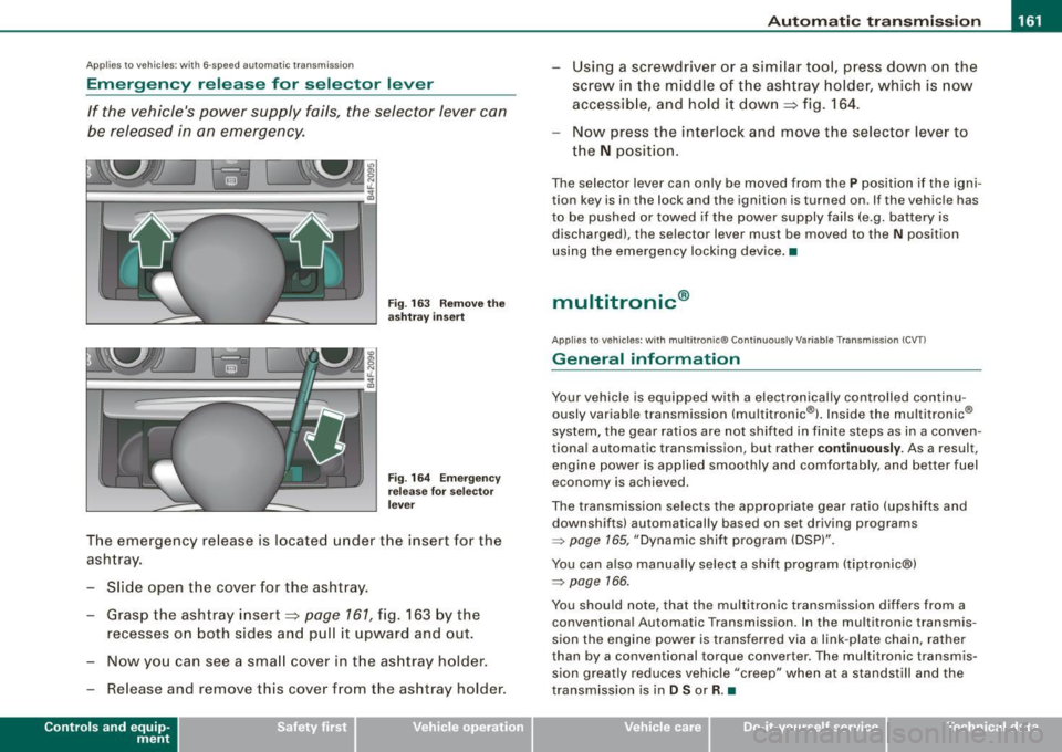
Fig . 163 Remove the
as htray i nsert
Fig . 164 Eme rge ncy
r elease fo r se lecto r
l ever
The emergency release is located under the insert for the
ashtray.
- Slide open the cover for the ashtray .
- Grasp the ashtray insert~
page 161, fig. 163 by the
recesses on both sides and pull it upward and out.
- Now you can see a sma ll cover in th e as htray holder.
- Release and remove this cover from the ashtray holder.
Contro ls and eq uip
ment
Using a screwdriver or a similar tool, press down on the
screw in the m iddle of the ashtray holder, which is now
accessib le, and hold it down
~ fig. 164 .
Now press the interlock and move the selector lever to
the
N position.
The selector lever can only be moved from the P position if the igni
tion key is in the lock and the ignition is turned on. If the vehicle has
to be pushed or towed if the power supply fails (e.g. battery is
discharged), the selector lever must be moved to the N position
using the emergency locking device .•
multitronic ®
Applies to v ehicl es: wi th mul titroni c® Con tinuou sly Variab le Transm issi on (C VTl
General information
Your vehicle is equipped with a electronically controlled continu
ously variable transmission (multitronic®l. Inside the multitronic ®
system, the gear ratios are not shi fted in finite steps as in a conven
tional automatic transmission, but rather
contin uously. As a result,
engine power is applied smoothly and comfortably, and better fuel
economy is achieved.
The transmission selects the appropriate gear ratio (upshifts and
downshifts) automatically based on set driving programs
=> page 165, "Dynamic shift program (DSP)".
You can also manually select a shift program (tiptronic®)
=> page 166.
You should note, that the multitronic transmission differs from a
conventiona l Automatic Transmission . In the multitronic transmis
sion the engine power is transferred via a link -plate chain, rather
than by a conventional torque converter. The multitronic transmis
sion greatly reduces vehicle "creep" when at a standstill and the
transmission is in
D Sor R. •
Vehicle care I I Technical data
Page 167 of 398
_______________________________________________ A_ u_t _o _ m_ a_ t _i_ c_ t_r _a _n _ s_ m __ is_s_ i _o _ n __ llll
Autom ati c selec to r l eve r lock
The se lector lever is locked in the P and N positions when the igni
tion is turned on . To move the lever from these positions the driver
must depress the brake pedal. As a reminder to the driver, the
follow ing warning appears in the instrument cluster disp lay when
the selector is in
P and N :
When stationary app ly footbrake while selecting gear
A time delay e lement preven ts the selector lever from locking when
it is moved through the
N position (going from R to Dl. The locking
e lement will lock the selector lever if the lever is left in N (Neutral)
for mor e than approximately 1 second, without the brake peda l
being pressed .
At sp eeds above about 3 mph (5 km/h) the Automatic Shift Lock is
automatically deactivated in the
N posi tion .
Interl ock button
The lock button on the selector lever prevents the lever from being
accid entally sh ift ed into certain pos it ions. Pressing th is button
deactivates the selector leve r lock . Dependi ng on the direction of
the shift, the se le ctor lev er locks a t different positions . Th e positions
are highligh ted in the illus trati on =>
page 164 , fig. 167 .
Igniti on k ey saf ety in te rlo ck
The key canno t be removed from the ignition un less the selector
lever is in th e
P park position . When th e ignition k ey is remov ed, the
selector lever wil l be l ocked in the
P posi tion .•
A pplies to veh ic les : wit h mu ltit ro nic® Cont inuous ly Va riab le Transm iss io n (CVT )
Kick-down
The kick- down feature allo ws the ve hic le to generate
maximum acceler ati on .
When you press the acce lerator pedal beyond the resistance point
t hat is reached at ful l th rottle, the transmission wi ll select a lower
gear ra tio bas ed on vehic le spe ed and engine RPM. The engine RPM
Controls and equip
ment
wi ll be control led to produce maximum vehic le acceleration as long
as yo u conti nue to press the acce lerato r pedal beyond this resis
tance point .
& WARNING
Be careful when us ing the ki ck-down feature on slippery roads .
Rapid acceleration may cau se the vehicle to skid . •
A pplies to veh icl es : wi th mu ltitro nic® C ontinuo usly V ari ab le Tra nsm iss ion (CVT)
Dynamic shift program (DSP)
The multitronic® tr ansmissi on is elect ro nic ally
controlled.
The transmission se lects the appropriate gear ratio (upshifts and
downsh ifts) automatical ly based on preset driving programs.
The transmission wil l selec t one of the
economy programs when
yo u drive at a steady speed o r a gra dually changing speeds without
heavy acceleration . T his gives bes t fuel efficiency , with early
upshifting and delayed downshif ting .
The transmission will au tomat ically select the
s porty shift programs
when you drive at higher speeds, or with heavy acce leration and
freque ntly changing speeds . Upshifts are delayed to make full use
of engine power. Downshifting takes place at higher engine speeds
t han in t he economy programs .
The se lection of the most suitable shift program is a continuous,
automatic process . The driver can also make the transmission
sw itch to a spor ty progra m by
quickly pressing down the gas peda l.
This caus es the transmission to shift down into a lower gear ratio
and makes qu ick acceleration possible (to pass another vehic le) You
do not need to press the gas peda l into the kickdown range . After
the trans missi on has upshifte d, the o riginal p rogram is selected
according to your driving style . _.,
I • •
Page 170 of 398
•L---=A....::...: u:;.. t:..: o:..::....: m.....;::. a..;:t :;..ic ~ t:..: r..;: a ..:..; n.....;::. s..:.m ;.;..:. is::.. s .::....:. io::....:. n;__ ____________________________________________ _
Applies to vehic les: with mul tit roni c® Cont inuous ly Variab le Transmission (CVTl
Emergency release for selector lever
If the vehicle's power supply fails, the selector lever can
be released in an emergency.
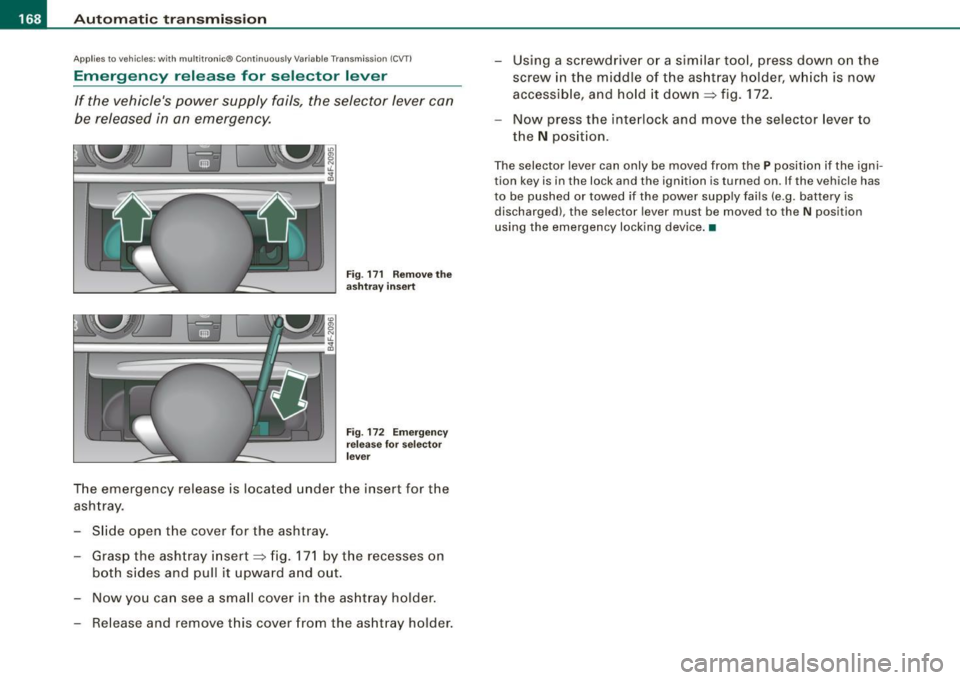
Fig . 171 Remove the
ashtray insert
Fig . 172 Emergency
release for selector
lever
The emergency release is located under the insert for the
ashtray.
- Slide open the cover for the ashtray.
- Grasp the ashtray insert~ fig. 171 by the recesses on
both sides and pull it upward and out.
- Now you can see a small cover in the ashtray holder.
- Release and remove this cover from the ashtray holder. -
Using a screwdriver or a similar tool, press down on the
screw in the middle of the ashtray holder, which is now
accessible, and hold it down ~ fig. 172.
- Now press the interlock and move the selector lever to
the
N position.
The selector lever can only be moved from the P position if the igni
tion key is in the lock and the ignition is turned on. If the vehicle has
to be pushed or towed if the power supply fails (e .g. battery is
discharged), the selector lever must be moved to the N position
using the emergency locking device. •
Page 173 of 398
![AUDI S6 2009 Service Manual Audi Parking System -
----------------=----=------
Rear frequency adjustment
- Pressthe (CAR]function button.
- Select
Audi parking system.
- Select Rear frequency when you want to cha AUDI S6 2009 Service Manual Audi Parking System -
----------------=----=------
Rear frequency adjustment
- Pressthe (CAR]function button.
- Select
Audi parking system.
- Select Rear frequency when you want to cha](/img/6/57595/w960_57595-172.png)
Audi Parking System -
----------------=----=------'
Rear frequency adjustment
- Pressthe (CAR]function button.
- Select
Audi parking system.
- Select Rear frequency when you want to change the
frequency of the rear audible signal generator.
When adjusting the volume and frequency, the new setting will
sound for approx. 2 seconds from each audible signal generator.
The volume and frequency settings are automatically stored and assigned to the master key with remote control.
& WARNING
• You should always adjust the volume and frequency of the
chimes so that you can easily hear the acoustic distance warning
even if the radio is playing, the air-conditioner blower is on High or
there is a high level of outside noise.
- Check the settings whenever anyone else has driven the
vehicle before you. •
Con tro ls and eq uip
ment
Audi Parking System (rear, with rear
view camera)
A pp lies to veh ic les: w ith Aud i Par king System ( rear) and re ar-view came ra
Acoustic parking system in the rear , with rear
view camera
The acoustic parking system gives an acoustic signal
when detecting obstacles, and the rear -view camera
offers further aid in the parking process.
OOID ;
r--= ===~~=~~;;;;;;;;~, ---;!
l_..:..:-=.: ~f---=====:=~.
Activation
Fig . 174 Rear lid: Loca
tion of the rear-view
camera
-Put the vehicle in reverse gear, the acoust ic parking
system with rear-view camera is activated automatically.
Activation of the acoustic parking system is confirmed by
a brief acknowledgement sound.
Deactivation
- Take the vehicle out of reverse gear. The acoustic park ing
system is immediately deactivated, and the rear -view
camera picture is deactivated automatically after a period of about 15 seconds, or
~
Vehicle care I I irechnical data
Page 182 of 398
• .___A_ u_d_ i _P _a_ r_ k_ i_ n ..:g=-- S_ y=-- s_t _ e _m _____________________________________________ _
& WARNING (continued)
• Maintain plenty of distance from an obstacle, so that your
outside mirror or a corner of your vehicle does not collide with any
obstacles - danger of accident!
• The Audi Parking System is not a substitute for being careful
and alert when backing up. Be especially careful during parking
and similar maneuvers. Always watch where you are driving and
make sure that nothing is in the way.
• When maneuvering or parking, do not only use the MMI Display
for orientation. Certain objects -depending on the screen resolu
tion -may not, or not entirely, be displayed ; for example trailer
hitches, chains, narrow posts, or fences . •
Settings in the MMI
App lies to veh ic les: witn Av(li Pi, rk ing System (rear! and rear-view camera
Adjusting the chimes -option 1
The volume and the pitch (frequency) of the chimes can
be adjusted in the MM/.
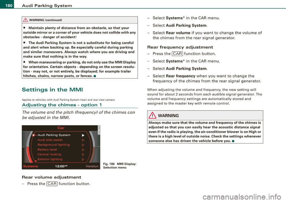
Fig . 186 MMI Display:
Selection menu
Rear volume adjustment
- Press the [CARI function button. -
Select
Systems * in the CAR menu .
- Select
Audi Parking System .
-Select Rear volume if you want to change the volume of
the chimes from the rear signal generator.
Rear frequency adjustment
- Press the [CAR I function button.
- Select
Systems* in the CAR menu .
- Select
Audi Parking System .
-Select Rear frequency when you want to change the
frequency of the chimes from the rear signal generator.
When adjusting the volume and frequency, the new setting will
sound for about 2 seconds from each audible signal generator . The
volume and frequency settings are automatically stored and assigned to the master key with remote control.
& WARNING
Always make sure that the volume and frequency of the chimes is
adjusted so that you can easily hear the acoustic distance signal
even if the radio is playing, the air-conditioner blower is on High or
there is a high level of outside noise. Check the settings whenever someone else has driven the vehicle before you. •