warning light AUDI S6 2009 Workshop Manual
[x] Cancel search | Manufacturer: AUDI, Model Year: 2009, Model line: S6, Model: AUDI S6 2009Pages: 398, PDF Size: 43 MB
Page 140 of 398
• ..__A_ d_a...: p:,..._ ti_v _ e_ C_ ru_ is_ e_ C_ o_n_ t_ r_ o _ l ___________________________________________ _
tained. The ACC system is not switched off, and increased attention
to the traffic situation is absolutely necessary. The following may be
reasons why the message
ACC functionality limited appears:
• The ACC sensor is dirty . The ACC system is not reacting, or is not
reacting correctly, to moving vehicles up ahead in your lane of
travel.
• There may be very light traffic on and there is nothing that marks
the side of the road (for example, guard rails, traffic signs, trees). As
soon as a moving vehicle up ahead is detected again, ACC becomes
active again and the message disappears .
The ACC sensor is located in the area under the front license plate.
If the ACC sensor is dirty or blocked, clean the area to restore system
operation.
ACC not available
The text message ACC not available appears, for example, if the
temperature of the brakes is excessive . Adaptive Cruise Control is
temporarily not available. A warning tone sounds as a reminder.
ACC not available!
The text message ACC not available! appears in the event of a
malfunction. Adaptive Cruise Control is turned off. A warning tone
sounds as a reminder. Have the system inspected by a qualified
dealership .
ACC sensor blocked !
The text message ACC sensor blocked ! appears when the ACC
System can no longer accurately detect vehicles moving up ahead
in your lane of travel. Adaptive Cruise Control is turned off. A
warning tone a lso sounds as a reminder.
To decide whether it is necessary to switch off the ACC (ACC sensor blocked
!) or if it is only a temporary condition (ACC Functionally
limited), the system will also takes into consideration the outside
temperature and/or the windshield wiper operation.
The ACC sensor is dirty or blocked (e.g. leaves, snow) . The
ACC sensor is located in the area under the front license plate .
If the ACC sensor is dirty or blocked, clean the area to restore system
operation.
EPB activation
Th e text message EPB activation appears if emergency braking was
manual ly initiated with the Electromechanical Parking Brake (EPB).
The Adaptive Cruise Con trol is turned off . This is accompanied by a
warning tone.
Speed
The set speed in mph (Canada km/h) always appears when saving or
changing the speed in Adaptive Cruise Control~
page 130 , "How is
the speed stored?" and~
page 131 , "Changing stored speed".
Selector lever position!
The text message Selector lever position! appears when the
selector lever is moved to position
N. In this position, Adaptive
Cruise Control is not available. •
Applies to vehicles : with Ada ptive Cruise Cont rol
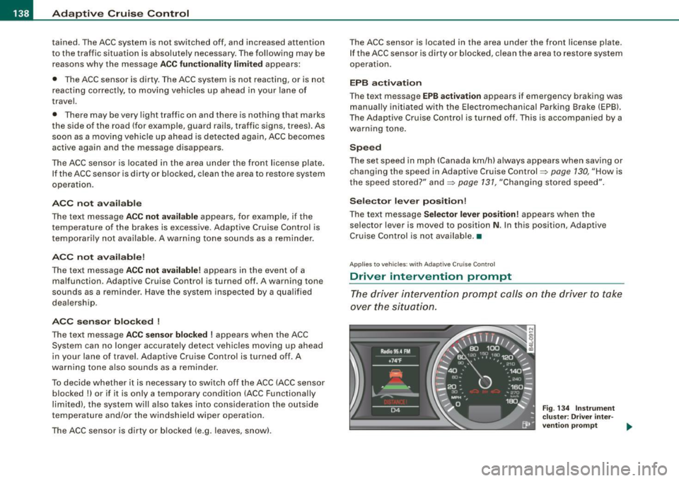
Driver intervention prompt
The driver intervention prompt calls on the driver to take
over the situation.
Fig . 134 Instrument
cluster: Driver inter-
vention prompt
~
Page 141 of 398
_____________________________________________ A_ d...;a..! p~ ti_v _ e---- C_ ru_ is_ e ___ C.::..: o;.:.n..:.. t.:.: r...; o:.. 1-----JIIII
In certain situations, the braking power of the Adaptive Cruise
Control is no t enough to maintain an adequate distance to the
vehicle up ahead . In these situations, the Adaptive Cruise Contro l
calls the driver to take action.
The
driv er in tervention pr omp t alerts you visually and audibly to
take over.
• A red vehicle is shown in the instrument c luster display
=>
page 138, fig. 134 .
• The text
DISTANCE! appears in the status line .
• The indicator light~'" '~ in the speedometer b links red.
• A warning tone sounds .
[ i J Tip s
• If the Adaptive cruise control initiates braking, the hydraulic
brake system is under pressure . Therefore, the brake peda l distance
is shorter and the pedal "fee ls" harder .
• Adaptive Cruise Contro l is switched off after pressing the foot
brake. The speed saved up this point can be resumed .
• To resume the saved speed, release the brake pedal and press
the control lever=>
page 132, "Turning Adaptive Cruise Cont ro l off
temporarily" .
• I f you use the accelerator to go faster than the speed of the
vehicle ahead of you, the
drive r inte rv e ntion prompt will not be
accompanied by a warning signal.
• If the speed you previously set is exceeded, the indicator light in
the speedometer wi ll switch off. •
Controls and equip
ment
Ap plies to veh ic les : w ith A dapt ive Crui se Co nt rol
MMI settings
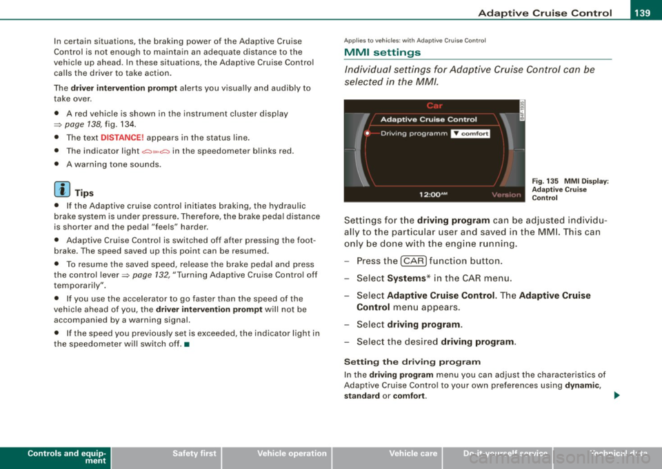
Individual settings for Adap tive Cruise Control can be
selected in the
MM/ .
Fig. 135 MMI Disp lay :
Ad aptive C ruise
C ontrol
Sett ings fo r th e driving program can be adjusted individu
ally to the p artic ular user and saved in the MML This can
only be do ne with the eng ine r un ning.
Press the
I CAR] fu nction button.
Select
Systems * in the CAR menu .
Select
Adaptive Cruise Control . The Adaptive Cruise
Control
menu appears.
Selec t
driving program.
Select the desired driving program .
Sett ing th e dr iving pr ogram
In the driv ing prog ram menu you can adjust the characteristics of
Adaptive Cruise Contro l to your own preferences using
d ynami c,
s ta nd ard
or comf ort . _.,
I • •
Page 145 of 398
Audi lane ass is t 11111 -----------------------------------
Audi lane assist
Lane assist
A pplies to veh icles : with lane assist
Description
Lane a ssist helps you keep y our vehicle in your lane .
Lane assist uses a camera to detect lane boundary lines. If the
system detects that your vehicle is about to leave a lane boundary
line, the steering wheel
vibrates to alert the driver. If lane assist
detects boundary lines on both sides of the vehicle's lane, the
system enters active standby mode, which is indicated by the green
indica tor light /: on the instrument cluster .
I f the system is in active standby mode and the turn signal is acti
vated before driving ov er the boundary line, the warning does not
occur since the sys tem allows for intenti onal lane changes.
The system is designed for driving on freeways and expanded high
ways and t hus works on ly at speeds of 40 mph (65 km/h) or mo re .
& WARNING
• Lane ass ist will not k eep your vehicle in your lane. The sy stem
only warns the d riv er w hen t he vehicle i s le av ing the lan e. The
driv er is alway s re spon sible for keeping the vehicle in the lane.
• The camera is not able to d ete ct all lane boundary lines and in
s o me cases might al so dete ct lane str ucture s or objects as
boundary lines . This c an le ad to in corre ct wa rning s or warnings
that fa il to go off at all .
• The camer a's visibili ty ca n be i mpaired by vehi cle s ahe ad of
you , for instan ce, or by rain , snow , h eavy spray or li ght shining into
th e cam era lens . Thi s can ca use lane as sis t to f ail to d ete ct
boundary line s. •
Con tro ls and eq uip
ment
Ap plies to vehi cles : wi th la ne assi st
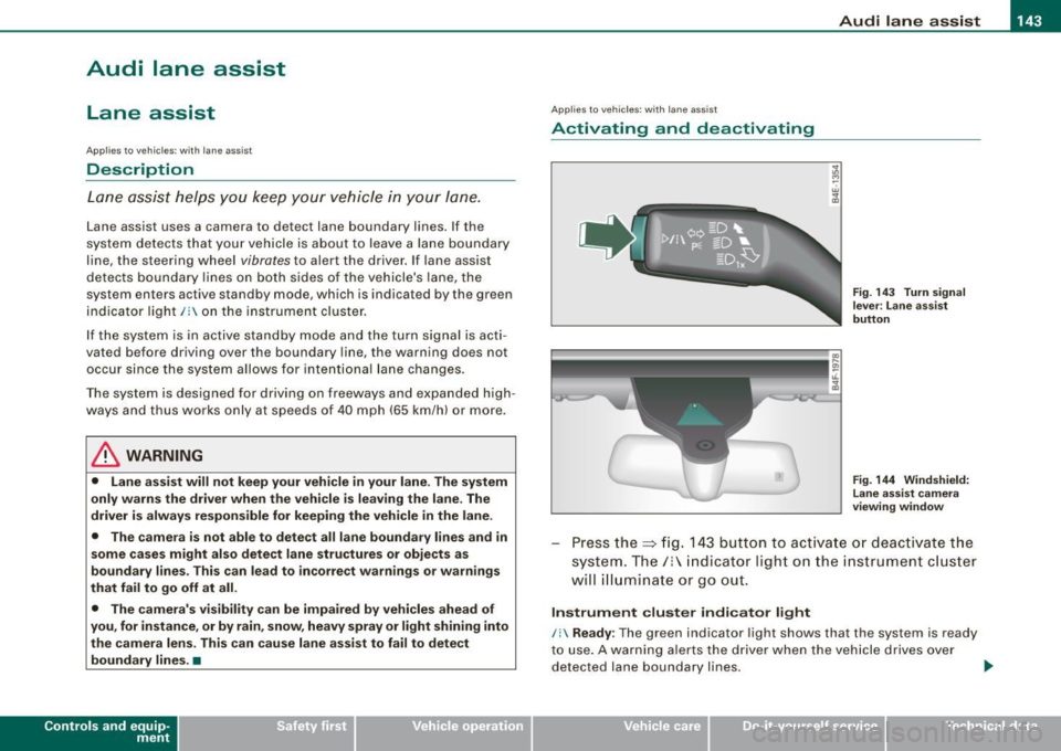
Activating and deactivating
Fig . 14 3 Turn signal
l ev er: La ne assis t
butt on
F ig . 144 Win dshie ld:
L ane assist ca mera
v iewing win dow
Press the :::> fig. 143 button to activa te or deactivate the
syst em . T he/ : in dica tor ligh t on t he i nstrument c luster
will illuminate or go out.
Instrument c lu ster indi ca tor light
/: Ready:
The green indicator light shows that the system is ready
to use . A warning a lerts the drive r when the veh icle drives over
dete cted lane boundary l ines. .,.
Vehicle care I I irechnical data
Page 146 of 398
• .___A_ u_ d _ i_l_a _n _ e_ a_ s_s _is _ t _________________________________________________ _
I Not ready: The yellow indicator light shows that the system is
turned on but unable to send a warn ing. This can be due to the
following:
• There are no boundary lines, or there is on ly one boundary line
present .
• The boundary lines are not detected (e.g. due to snow, dirt, wet
conditions or light shining into the camera lens).
• More than two boundary lines (such as at construction sites) are
located in the vehicle's lane.
• The vehicle's speed is below the speed needed to activate it,
which is about 40 mph (65 km/h).
• The lane is narrower than about 8 ft . (2.5 ml, or wider than about
16 ft. (5 ml.
• The curve is too sharp.
Notes on the instrument cluster display
When the lane assist turns off automatically, the instrument cluster
indicator goes out and one of the following messages appears on
the display:
Audi lane assist not available: Currently no sensor vision
This message appears when the camera can no longer function
because it cannot detect the boundary lines. This may be due to the
following :
• The exterior s ide of the camera viewing window=>
page 143,
fig. 144 is covered with dirt or ice. Clean this part of the windshield.
• The camera v iewing window is fogged up on the inside. In this
case, wait until the fog disappears before turning lane assist on
again.
• The system was unable to detect boundary lines over an
extended period of time due to road conditions (such as snow
covered lanes). Do not turn lane assist on again until the lines can
be more easily detected.
Audi lane assist not available
A temporary malfunction is preventing lane assist from operating .
Try turning on lane assist again a t a later time.
Audi lane assist: system fault
The system should be checked by an authorized Audi dealer or other
qualified workshop .
[ i ] Tips
• Make sure that the camera viewing window=> page 143, fig. 144
is not covered by stickers or similar objects .
• Always keep the camera viewing window clean. This can usually
be done by operating the windshield wipers. •
Applies to vehicles: with lane assist
MMI settings
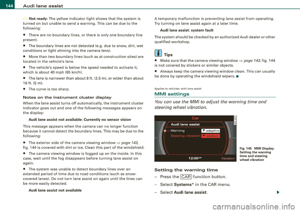
You can use the MM/ to adjust the warning time and
steering wheel vibration.
Setting the warning time
Press the I CAR] function button.
- Select
Systems * in the CAR menu .
- Select
Audi lane assist.
Fig. 145 MMI Display:
Setting the warning
time and stee ring
wheel vibration
Page 149 of 398
_________________________________________________ A_u_ d _ i _s ... i __ d _e:....: a.:..: s:.. s:.. i:..: s :..:t;___ftllll
Deactivating
- Press t he button again . T he ind icato r light on the butto n
goes out.
T he system works at speeds faster than 19 mph (30 km/h) .
& WARNING
• Improper reliance on the side assist system can cause colli
sions and seriou s per sonal injury:
- Never rely only on side assist when changing lanes .
- Always check rear view mirrors to make sure that it is safe to c hange lanes.
• Side assist cannot detect all vehicles under all conditions
danger of accident!
• Side assist cannot detect vehicles in time to alert you when
they approach from behind at very high speed , or fall drop back
very quickly.
• The radar sensor's
vision can be reduced or entirely blocked by
rain , snow, and heavy spray . This can result in side assist not
adequately detecting veh icles or , in some cases, not detecting
them at all . Always keep an eye on the direction you are traveling
and the relevant area around the vehicle.
• Please note that side assi st indicates there are approaching
vehicles, or vehicles in your bl ind spot , only after your vehicle has
reached a driving speed of at lea st 19 mph (30 km /h).
• S ide assist signal does not work around tight corners (turning
radiu s less than 328 feet, or 100 m l.
• Side assist is no replacement for the driver's full attention . The
d river alone is responsible for lane changes and similar driv ing
maneuvers. Always keep an eye on the d ire ction you are travel ing
and the relevant area around the vehicle .
Controls and equip
ment
0 Note
• To e nsu re t hat you do not adverse ly a ffect s ide assist, do not
b lock the area on the rear bumper where the radar sensors are
located w it h f oreign objects (s uch as st ickers or bicycle rac ks).
• M ake su re that the signal light on the o utside mi rror is not
b loc ked by st ic ke rs or ot her items.
[ i ] Tips
• Side ass ist automaticall y deact ivates i f it detects t hat t he ra dar
sensors are blocked=> page
153. The indicator light on the button
goes out.
• The area on the bumper whe re the rada r sen so rs a re loca ted
must cons iste ntly re mai n fr ee o f snow, ice, and heavy so iling so t hat
side assist can function properly. Follow the additiona l notes on
=> page
154.
• Additiona l tinting on the front side windows can make it ha rder
t o see and co rrect ly unde rsta nd the s ignal light o n the outs ide
mirror.
• For Declaratio n of Comp liance to Un ited Sta tes FCC a nd I ndus try
Canada regulations => page
375 . •
I • •
Page 154 of 398
1111 Audi side assist
--------------------
G) Sig nal o n outs ide mirr or does no t l ight up
If you activate your turn signal in driving situat ion @, the signal sti ll
does not light up on the outside mirror:::::,
& in "Safety tips" on
page 154. •
Applies to vehic les: with side assist
MMI settings
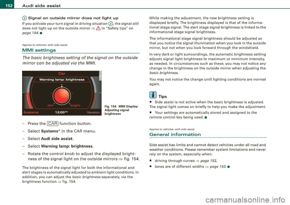
The basic brightness setting of the signal on the outside
mirror can be adjusted via the MM/.
- Press the I CAR I function button.
- Select
Syst ems * in t he CAR menu.
- Selec t
Audi side a ssis t.
Selec t Warning lam p: brightn ess.
Fig. 154 MMI Disp la y:
Adj ust ing s igna l
br ightn ess
Rotate the contro l knob to adjust the displayed bright
ness of the signal light on the outside mirrors~ fig. 154.
The brightness of the signal light for both the informational and
a lert stages is automatica lly adjusted to ambient light cond itions . In
addition, you can adjust the
basic brightness separately, via the
brightness function :::::, fig. 154 . Whi
le making the adjustment, the new brightness setting is
displayed briefly. The brightness disp layed is that of the informa
tiona l stage signal. The alert stage signa l brightness is linked to the
informational stage signal brightness .
The informat iona l stage signal brightness shou ld be adjusted so
that you notice the signal illumination when you look in the outside
m irror, but not when you look forward through the windsh ield .
I n very dark or light surroundings, the automatic brightness setting
adjusts signal light brightness to maximum or minimum intensity,
as needed . In circumstances such as these, you may not notice any
change in the brightness on the outside mirror when adjusting the
basic brightness.
You may not notice the change until lighting conditions are normal
aga in.
[ i ] Tips
• Side assist is not active when the basic brightness is adjusted.
T he signal light comes on briefly to he lp you make the adjustment.
• Your settings are automatically stored and assigned to the
remote contro l key being used .•
Ap plies to vehic les: with side assist
General information
Side assist has lim its and cannot detect vehicles under a ll road and
weather conditions. Please remember system limitations and never
rely on the system, especia lly when:
• driving through curves:::::,
page 153,
• lanes are of different widths:::::, page 153. •
Page 155 of 398
Audi sid e as sis t -
-------------------'
Applies to vehicle s: with side assist
When driving through curves
Side assist canno t detect veh ic les in curves with a turning radius of
less than 328 feet (100 m) .
When driving through a curve, it is possible that side assist may register a vehicle two lanes over, and the signal on the outside
mirror will light up .•
Appl ies t o vehicles: with side ass is t
lane width
Con tro ls and eq uip
ment
•
-
-
Fi g. 155 lanes o f a
n ormal width are in
d etec tio n area
Fi g. 156 Nar row lane s:
Si de assis t may detec t
vehi cles tw o l ane s
away
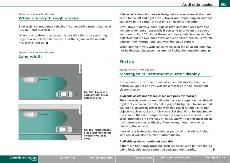
Side assist's detection area is designed to cover lanes of standard
width to the left a nd r ight of your trave l lane, depending on whether
you drive in the center of your lane or c loser to the edge.
I f you drive in narrow lanes, side assist's detection area may also
inc lude other lanes - especially if you tend to drive on the edge of
your lane=> fig. 156. Under these conditions, vehicles can a lso be
detected tha t are two lanes away, a nd s ide assist then could switch
between the informationa l and warning stage signa ls.
When driving in very wide lanes, vehicles in the adjacent lane may
not be detected because they are not inside the detection area .•
Notes
App lies to vehic les : with side assist
Messages in instrument cluster display
If side assist turns off automatically, the indicator light on the
b utton will go out and y ou wi ll see a message in the instrument
cluster disp lay:
Audi side a ssist not avail able : s en sors po ssibly blocked
The side assist sensors are built into the rear bumper on the left and
right (not visible on the outside) =>
page 146, fig. 146. To ensu re that
you do not adversely affect the way side assist functions, foreign
objects (such as stickers o r bicyc le racks) should not be attached to
the area on the rear bumper where the sensors are located . If side
assist functi ons are adversely affec ted, you w ill see this message in
the instrument cluster display. Remove anything that may be
b locking the sensors.
I f no vehic le is detected for a longer pe riod of time while driving ,
side assist will also switch off automatically .
Audi sid e ass is t currently not available
If there is a temporary problem (such as the vehicle's ba ttery cha rge
being low) , side ass ist cannot be activated temporarily . .,_
Vehicle care I I irechnical data
Page 159 of 398
_______________________________________________ A_ u_t _o _m_ a_ t_ i_ c _ t_r _ a _n _s_ m_ i_ s _ s_ i_ o _ n _ ___._
R -Reverse
The transmission will automatically select the lowest gear ratio
when you shift into reverse .
Select
R only when the vehicle is at a full stop and the engine is
running at idle speed=>
& in "Driving the automatic transmission"
on
page 155 .
Before you move the selector lever to R, press both the button in the
handle of the selector leve r
and the brake pedal at the same time .
When the ignition is on , the backup lights illuminate when the
selector lever is moved into
R.
N -Neutral
The transmission is in neutral in this position . Shift to this position
for standing with the brakes applied=>
page 157.
When the vehicle is stationary or at speeds below 3 mph (5 km/h),
you must always apply the footbrake befor e and while moving the
lever out of
N.
D -Normal position for driving forward
Position Dis for normal city and highway driving. It ranges from zero
to top speed and all gears shift automatically , depending on engine
load , driving speed and automatically selected shift programs.
When the vehicle is stationary or at speeds below 3 mph (5 km/h),
you must always apply the foot brake before and while moving the
lever to
D out of N.
In certain circumstances it may be advantageous to temporarily
switch to the manual shift program to manually select gear ratios to
match specific driving conditions=>
page 159.
S -Sport position
Select this position for sportier performance . In this position, the
transmission will not upshift as soon, allowing the vehicle to use the
increased power available at higher engine speeds to achieve live
lier acceleration.
Con tro ls and eq uip
ment
When the vehicle is stationary or at speeds below 3 mph (5 km/h),
you must always apply the foot brake before and while moving the
lever to
S out of N.
& WARNING
Read and follow all WARNINGS => & in "Driving the automatic
transmission" on
page 155.
0 Note
Coasting downhill with the transmission in N and the engine not
running will result in damage to the automatic transmission and
possibly the catalytic converter. •
Applies to vehi cle s: with 6 -speed automati c tra nsm is si on
Automatic Shift Lock (ASL)
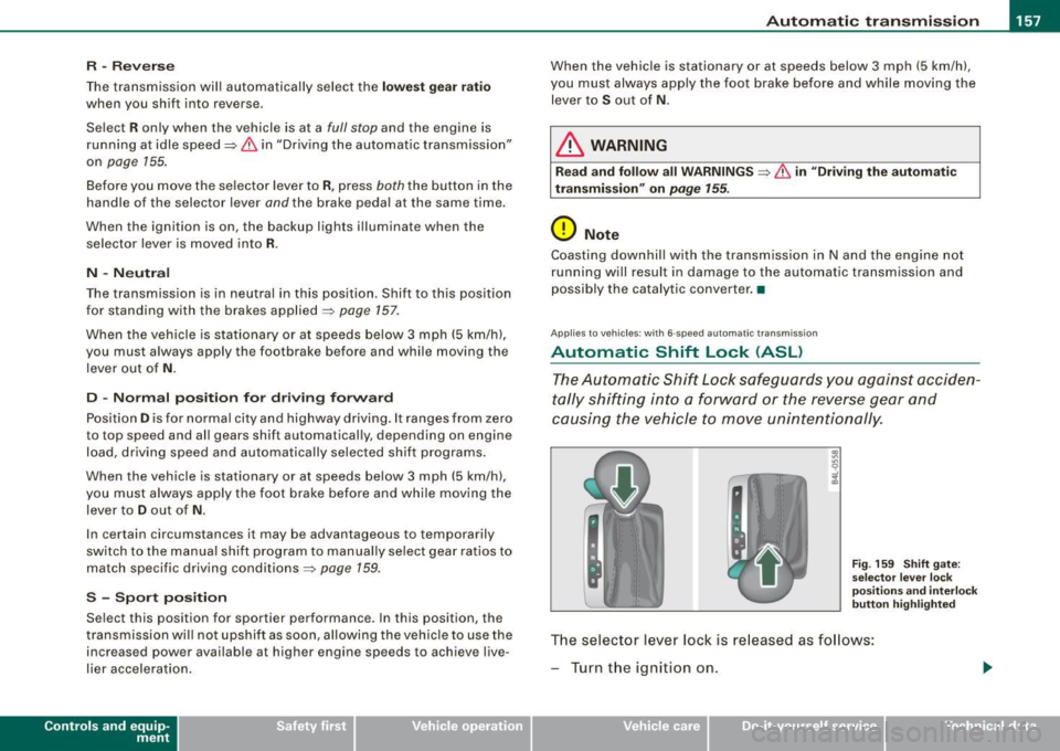
The Automatic Shift Lock safeguards you against acciden
tally shifting into a forward or the reverse gear and
causing the vehicle to move unintentionally.
Fig. 159 Shift gate:
selector lever lock
positions and interlock
button highlighted
The selector lever lock is released as follows:
- Turn the ignition on.
Vehicle care I I irechnical data
Page 160 of 398
_L-_:..A.:.u:::..: t.:o :..m.:..:.; a:::..: t:.. ic:....: t:.:. r..:a :.. n...:..:: s.:.m _;_:.:, i..::s ..:s :.:.i..:o :..n_;_ _______________________________________________ _
-Step on the brake peda l. At the same time press and hold
the interl ock butto n on t he side of the gear selector kn ob
:::::, fig . 159 with you r thumb until you have moved the
se lector lever to the desired pos ition.
Automatic selec tor lever lo ck
The selector lever is locked in the P and N positions when the igni
tion is turned on. To move the leve r from these positions the driver
must depress the brake peda l. As a reminder to the dr iver , the
following warn ing app ears in the instrument c luster display when
t h e selector is in
P and N :
When station ary apply fo otbr ake while sele cting ge ar
A time de lay e lement prevents the se lector lever from lock ing when
it is moved through the
N position (going from R to Dl. The locking
e lement will lock the selector lever if the l eve r is l eft in N (Neutral)
for more than approximately 1 second , without the brake pedal
being pressed.
At speeds above ab out 3 mph (5 km/h) the Automatic Shift Lock is
automatically deac tivated in the
N position .
Interlo ck button
The lock bu tton on the s elector lever prev ents the lever from being
accidentally shifted into certain positions . Press ing this bu tton
deac tivates the selec tor lever lock . Depending on the dir ection of
t he shift, the se lector lever locks at diffe rent positions . The positions
are highlighted in the illustration~
page 157, fig. 159 .
Ignition key safet y interlock
The k ey cannot be remov ed from the igni tion un less the selector
lever is in the
P park p osition. When the ign ition key is removed, the
selector lever wil l be locked in the
P position. •
Applies to vehicles: w it h 6 -spee d au tomat ic tra nsm ission
Kick-down
The kick-down feature allows the vehicle to generate
maximum acceler ation.
When you press the accelerator pedal beyond the resistance po int
that is reached at fu ll thrott le, the transmission will se lect a lower
gear rat io based on vehicle speed and engine RPM . The engine RPM
wi ll be contro lled to produce max imum vehicle acceleration as long
as you continue to press the accelerator pedal beyond this resis
tance point .
& WARNING
Be careful when u sing the kick-down feature on slippery road s.
Rapid ac celerat ion may cause the veh icle to skid. •
Applies to veh icles : wit h 6-s p ee d au to m ati c tra nsmiss ion
Dynamic shift program (DSP)
The aut om atic tr a nsmission is electronically controlled.
T he transmission is self adapting and wi ll automati cally se lect the
b est shift program suited to the driving condi tions and drivi ng s tyle.
The transmission wil l se lect one of the
e conom y programs when
you drive at a steady speed or a gradually changing speed withou t
heavy acceleration . This achieves optimum fuel efficiency, with early
upshifting and delayed downshifting.
The trans mission wil l au tomat ical ly select the
sporty shift programs
when you drive at higher speeds, or with heavy acce leration and
frequently changing speeds . Upshifts ar e delayed to make full use
of engine power . Down shifting takes place at higher engine speeds
t han in the economy programs . _.,
Page 164 of 398
• ..__A_ u_ t_ o_ m_ a_t _i c_ t_ r_ a _ n_ s_m _ is_ s _ io_ n _____________________________________________ _
App lies to vehic le s : w ith mul tit ron ic ® Cont inuous ly Varia ble Transm ission ( CVTl
Driving the multitronic ®
The gear ratio is continuously adapted to vehicle speed
and load .
Starting th e engin e
- The selector lever must be in N or P.
Start in g off
- Press and hold the bra ke pedal.
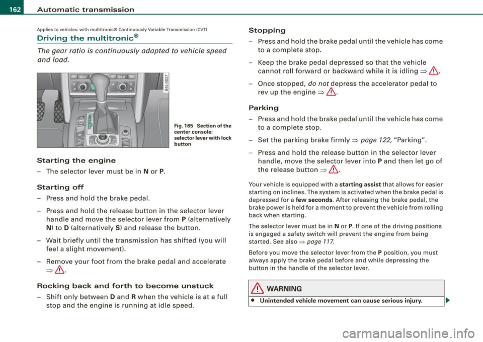
F ig . 165 Sec tion o f the
c en ter conso le:
sele ctor leve r w ith l ock
b utt on
- Press and hold the release button in the selector lever
handle and move the selector lever from
P (alternatively
N ) to D (a lternatively S ) and release the button .
- Wait br ie fl y until t he transm iss ion has shifted (you w ill
feel a slight movement ).
- Remove your foot from the brake pedal and acce lerate
~ & -
Ro cking ba ck and forth to b ecom e un stu ck
- Shift only between D and R when the vehicle is at a full
stop and the engine is running at idle speed .
Stopping
-Press and hold the brake pedal until the vehicle has come
to a comp lete stop.
- Keep the brake pedal depressed so that the vehic le
cannot ro ll forward or backward while it is idling ~& .
Once stopped,
do not depress the acce lera to r pedal to
rev up the engine::::!>&.
Pa rking
- Press a nd hold the brake peda l until the vehicle has come
to a comp lete sto p.
- Set the park ing brake firmly ~
page 122, "Park ing".
- Press and hold the release button in the selector lever
handle , move the selecto r leve r into
P and then let go of
the release button
~ & .
Your vehicle is equipp ed with a sta rtin g assist that a llows for easier
starting on inclines . The sys tem is activated when the brake peda l is
d epr essed for a
few se co nd s. Aft er r eleasing the brak e peda l, the
brake power is held for a moment to prevent the vehicle from rolling
back when starting .
The se lector lever must be in
N or P. If one of the driving positions
is engaged a safety switch wi ll prevent the engine from being
started. Se e also =>
page 117.
Before you move the selector lever from the P position, you must
a lways apply the brake pedal before and while depr ess ing the
button in the handle of the selector lever .
& WARNING
• Unintended vehicl e movem ent can cau se seri ous injury.